I believe PLLXO is the quintessence of crossovers. Super clean, no ill effect, just pure loveliness. But they have a huge problem. Matching with the actual amplifer and its input impedance. And especially your next amplier. Until now! Our hero enters - Adason!
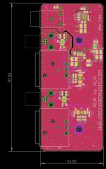
Here is his contribution to humanity - a buffered PLLXO.
His own thread:
https://www.diyaudio.com/community/threads/simple-active-crossover.368702/
I have a strong desire to try this out. This thing is sleak!
However, I lack any skill, or even talent, in the electrical field. I have to do this in the short brakes I have from cutting human tissue samples looking for cancer, and other unimportant tasks.
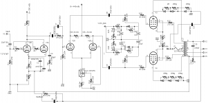
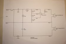
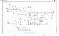
I have come up with this completing schematic which might help anyone who tries to mimic this circuit.
Some things I am trying to figure out:
¤ Bi-polar caps on input and output. Should probably be used.
¤ Dual Rail - important to understand how this works. See V+ and V- and ground in schematics.
Adasons preference is something similar to this PSU that can reduce the need for the 100uF/V35.
https://www.ebay.com/itm/164845881741?hash=item266194898d:g:ObUAAOSwxmdgj2z3&amdata=enc:AQAHAAAAwNGeP5fYh2oIx+yK4Io3k2fHDvEu5iQEkIL08ckzHZTCZERincMe2HroKGMBjI9NoePqlCIF04GR+QU43jNO/3SE6NKRPArKb8eDvh8Lhgtr3PSM1NmE3c7C2cJ99GSr5GFyHrxVm6oxJTKYz/Yuj6Xlceo0NN9gfvm1zdjGnQFIirgfSnixy3ZW1k/WGBwITaSy4U3TtIW7bX6Sjd8JnXKltnMAp0I7bkxrjvW2TcZIuZsMh6rbXCG9i4b9EM1rkA==|tkp:Bk9SR_jc5unWYA
¤ How to modify the circuit for other frequencies:
The schematic says first, choose C. Well, choose C based on what?
In Dave's pages, which Adason refers to, is says choose R.
Somewhat contradictory,
take
Let a known example of the 150Hz that Adason was working with:
If C= 0.1uF
Then,
R = 1/ (2 x Pi x "crossover frequency" x C
= 1 / (2 x Pi x "crossover frequency" x 0,1 uF
= 1 / (2 x Pi x 150Hz x 0.1uF
= 1 / (2 x 3.14 x 150 x 0.1uF) = 10k Ohm
Adason is using these values a lot in his schematic. I am not sure if every value is based on this formula.
And reversed:
C = 1/(2 x Pi x "crossover frequency" x 10 000 ohm
C = 1/(2 x Pi x 150Hz x 10 000 ohm)
= 1/(2 x 3.14 x 150 x 10 000 ohm)
= 1.06157113e-7 F
= 0.106 uF
= 0.1uF
0.1uF - same can be found everwhere in Adaons schematic.
According to Adason, if using a really clean PSU, you might not need to use the unmarked "rails ripple shaving caps", as ZM so kindly pointed out that they were called.
Anyone are welcome to help me and others to understands this circuit and solder ourselves a working example. Please correct it!


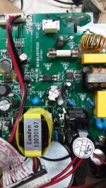
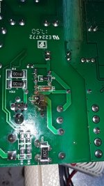
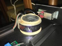
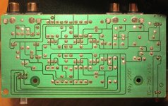
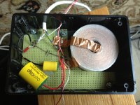
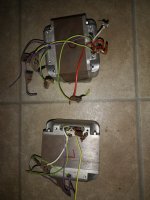
 i tried this board in two amps and the same ting happend ,2 output transistors blew and all the power supply mosfet.amp played clean and all of a sudden it blew.what on the drive card could cause this to happen?


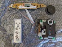

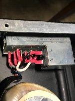

![IMG_5195[1].JPG](/community/data/attachments/990/990643-d31dcf3bb503d81d75d678e565c1eaca.jpg?hash=0x3PO7UD2B)