Measurement (ADC/DAC/CLK) power supply for ultra low noise

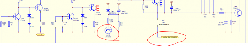
I've designed and built a Maida with a mosfet and LT3080 - that seems to work really nicely. Now I'm looking at developing and building the power supply for my ADC (+15V,-15V, +5V) with the requirement for clocking around 24.756MHz too. I naturally have a large number of questions. The main questions I have are around the power supply - possibly the best option would be having a battery or capacitor bank to provide the ±15V 70mA and the +5V. I'd also create a second +5V supply for the digital side.

I came across this Jim Williams article: https://www.analog.com/en/technical...rement-for-a-low-noise-voltage-reference.html . The interesting piece in this article for me is the low noise power supply, grounding and shielding later on. I've also seen the use of LiPo on here (I'm aware of the issues).

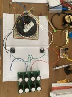
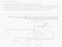
So one option is to use either a bank of super caps or Duracell NiMH 9V D-cell rechargeable to power the ADC. I would probably prefer the supercapacitots and use a current limited power supply to charge, disconnect, then allow the caps to provide power through an LDO. For example an 18-20V super cap bank to give 15V seems reasonable. I could even use the current limiting SMPS bench supplies as the chargers.

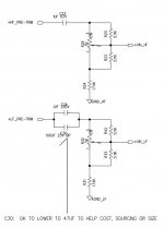
For the LDO I was considering LT3045s which should handle 18V. I'd use separate cap banks for +18V, -18V and two +8-12V. The current draw for the ADC supplies would be <100mA each but the +5V digital would be powering a RPI at 2A hence would sendup taking a larger cap bank and parallel.

Has anyone done this already? Any experiences I could learn from?

Marantz NR1604 low volume

Hi Guys,
I have a problem on my NR1604, my volume is stuck after using Bubblepnp app. The volume is very low (like -30db) on all network sources. Connecting a physical a source with cables, like a CD player or HDMI works fine. Where I can download the firmware? From what I read this is a know issue and it seems the only way to fix it is to apply again the firmware.
Thank you!

Looking to trade 100K Goldpoint Attenuator for a 20K Goldpoint Attenuator

As the title says, I have a almost new (tested in circuit for 1 hour) 100K Goldpoint attenuator, that works great and was not cheap! But I changed my application and would prefer a 20K attenuator. It's a long shot, but if you happen to be in the same but opposite scenario, and have a 20K attenuator but need a 100K let me know and we can swap!

Can anyone provide more specifics on the Fleetwood Deville?

I'm looking to see if anyone here has any specific information on the Fleetwood Deville. Love the look of the speakers and I'd like to try to build some myself. It looks as if the drivers are the B&C DE550 1" Compression Driver for the tweeter and the B&C B&C 8NDL51 8" Woofer. Please correct me if those are wrong. What I'm looking for are cabinet dimensions, port dimensions and length, crossover schematics, etc. Any help would be appreciated!

Marantz 5000 Record/Playback Freq Response

Hi everyone,

I’m really pulling my hair out trying to find a signal to complete this calibration. My stand alone signal generator can only go as low as 50mv

Procedure from manual below.

I have the Arta software which I can get down to -60db and I also have a 20db attenuator. However the input is to low.

Or am I going about this all wrong. Can someone talk me through this, I’d really appreciate some help with this.

Cheers J
837243D8-93A3-4720-A3F8-57373DA6F784.jpeg

Audiophiles and ASMR

I found this YouTube video on ASMR interesting as viewed through the lens of an audiophile. As explained in the video, ASMR is an auditory response phenomena where certain sounds are perceived as very intimate. Causing a very pleasurable neurological reaction in some listeners. Among other stimuli, ASMR is reported to occur from the sound of some music (mentioned at the 6:30 time mark of the video). Not all listeners seem to be sensitive to the effect. Among those who tend to be sensitive, however, are those who are introverted, or have some degree of anxiety.

I immediately thought about we audiophiles as a group. I’ve always wondered why so many of us are incessantly worried about minute aspects of our systems. About whether the sound we currently obtain could, maybe, be a smidge better if we changed from one brand of interconnect cable to some other brand, or whether our phono cartridge VTA is off a few degrees. Why some of us express the sensation of having an ‘eargasm’ when listening to live music, or to the sound really good playback. Why we are so overwhelmingly male. It’s unfortunate that a gender breakdown of ASMR sensitivity isn’t included in the video.

Login to view embedded media

replace 100uf cap with 0.1uf ?

*see attached schematic

the LF pre trim for the woofer, the output of which then gets fed to the 1st stage amp, uses a 100uf (nonpolar electrolytic) and a 0.1 uf film cap in parallel

what is the function of the 100uf? to block dc into the amp/ to protect the amp?

what would happen if i removed 100uf and only used the single 0.1uf film cap?

on the HF tweeter pre trim im using a poly/foil cap that sounds very nice and much better than oem

so id like to get the same cap but in 0.1uf for the woofer

Attachments

  • pre trim circuit.jpg
    pre trim circuit.jpg
    65.8 KB · Views: 199

Speaker testing without anechoic chamber

Hi,

I'm about to test some speakers at home with a measuring mic etc. On the one hand it would be useful to see how the speakers perform in a "typical" domestic setting but as a reference (and out of curiosity) I'd really like to know how the perform under anechoic conditions.

I remember seeing a web page that showed an alternative method: a very short burst of noise is played through the speaker and recorded. The burst is so short that the recording only contains the direct output of the speaker i.e. the recording time wasn't long enough to contain any reflections from the room boundaries, therefore anechoic.

Does anyone know what this method is called or have any links? Are there any draw backs with this approach?

Thanx in advance,
Dean.

Amplifier using MJL21193/94

Hi everyone! After building numerous chipamps now i'm heading towards discrete amplifiers. I know very little about discrete designs & still learning. It'll take time i believe but despite that i've no dearth of enthusiasm!

Anyway my question is how much power i can get from two pair of mjl 93/94 into 4ohm & 8ohm load(real world use)? Driver transistor recommendation? Actually still i'm struggling to understand SOA. Please help me 🙂

Attachments

  • 20211111_193822-1.jpg
    20211111_193822-1.jpg
    192.8 KB · Views: 1,093

Help design an output level matching jig

I'm toying around with a Nakamichi tape deck that has separate knobs for R/L recording levels and I'd like to make a test jig for matching the levels (the meters are not accurate enough).

The most basic idea could be a LED that is fed by the voltage difference between both channels, when it is dimmest it is matched (although resolution might not be great)
Or a row of LEDs that is centered when balanced and lit on either side depending on whether the voltage difference is positive or negative.
Also open to a display/voltmeter module but seems like it would be more complex.

I don't know where to start on how to design such a schematic, any help or suggestions would be appreciated.

putting tuned mass damper inside a speaker enclosure

just taking an idea from sonus faber lilium, it has a tuned mass damper insde the cabinet to reduce cabinet virbation

Login to view embedded media
now compare to taiwan101 tower it put a mass damper on the top of the building instead using the total length of the cabinet

Which one it the proper implementation ? to me it seems the tower is the proper implemntation becasue it also take account of the horizontal and vertical virbation.

Now we put this mass damper design into a vented box, shall we creat a seperate enclousre on top of the box so we can eliminate the accoustic sound the mass damper created ?

help with JBL 2360A project

Hi there,

I ve been looking for a Horn project since long ago.
i think I got lucky this time, a friend is giving me a pair of JBL 2360A for free.
i am worried by the size but i annot let pass this oportunity.
i am in Chile so importing these horns from usa would be imposible so here i am.

I am very ignorant about horns, but have seen a few projects with 2360A that alwais appealed to me a lot.

here some data to work with:

Room: 8mt width x 7mt long

dac: Buffalo IiI with balanced and single end output. can use both outpus if neccesary to feed two amplifiers

Amplifier: japanese SET 45 with Tango Irons (great stuff) 8ohms output only. not a lot of power so impedance should math.
i have also a SS 41hz.com 100W amplifier, i want to avoid it as much as possible, but I will use it with woofer if really really needed. At the moment I have a 97db woofer, so seems it will be necesary to match horns sensitivity.

tweeter: thinking to buy a jbl 2405h on ebay (because i love everest d55000 and fell in love with these tweeters)

mid: horn JBL 2360a, looking for good and cheap CD to go from 350-500hz to 6khz-8khz

bass: reaching quality 40hz-50hz should be ok for me. i already have a Eminence omega ori 18a with me and want to use it in the beggining to save cash, can get a 100db woofer later...

Crossover: I would rather passive, since I like my DAC and like my 45 SET amp, want to avoid touching sound as much as possible, but want a bunch more of sensitivity to drive my amp better.

Current speakers: 94db open baffle Saba green cones with 18inch woofer. first order passive crossover. i like it but is the weak link now for my System. mids are great but I lack detail and dynamics, I want more high end stuff.

so my questions:
1) does it sound good project, something to finish your speaker building career?
2) looking for a 2inch driver that can do the job, with quality sound. Buying in chile would be much cheaper, but only optons at the moment seems to be here:
Selenium d3305ti
Eminence PSD 3006-8ohm
rcf n850 (more expensive, more power, dont know if better in Sound Quality)
the selenium is cheap at 200usd in Chile, and i tend to think it will sound good.
3) lots of CDs are 16ohms, my woofer is 8ohms, whats better to end up with a 8ohms load to the amplifier? 8 or 16ohms CD?


So your help and experience will be invaluable to make the right choices.
best,
Carlos

Dead-Time issue with IRS2092/2452AM

Hi,
I have created an amp based on IRS2452 which is design-wise very similar to IRS2092 (has differential inputs).
It is based on IRAUDAMP23 (schematics attached). The MOSFETs in schematics have been replaced by IPP530N15N3GXKSA1 which have much lower Gate capacitance.


I have a problem with shoot-through when the high-side MOSFET turns off (and low-side MOSFET turns on).

Although I have gate buffers installed, the driver inside the IRS first seems to slowly discharge to VBoost and then discharges the gate(or the gate buffer transistors) faster. Due to this slow discharge, I get a shoot-through.
See attached photos taken between R1409 and R1408(yellow) and R1419 and R1424(blue).


Any idea what could be the root cause ?

VBoost is 45V, -VBoost -45V - the other voltages are okay as well (the amp plays well but idle current is too high).


Regards,
Beetlebuster

Attachments

  • Bildschirmfoto vom 2021-11-13 15-02-42.png
    Bildschirmfoto vom 2021-11-13 15-02-42.png
    343.2 KB · Views: 781
  • SDS00002.png
    SDS00002.png
    7.8 KB · Views: 642
  • SDS00003.png
    SDS00003.png
    7.5 KB · Views: 616

2E26 Options

Hi,

I'm new here, I've read a lot of good stuff on threads here before.
I've been doing glassware amplification for about three years now, and i've come to thepoint there i'm learning how to design proper output stages.
Up till now, I've been learning all I need from education+diy. preamps, power supplies and triode power ( SE/PP) are things i can design already. at least they work😀

So, I finally decided to make an account and actually ask a question. 😱
I'ts about Pushpull Pentodes. I've already got a nice amplifier so now i'm working on an amp that doesn't only sound nice, but also looks nice- better than this: (i'm the engineer there, too)
Circuits Online - Forum - Show your projects! Part 26.


I was aiming for a mercury rectifier, a nice glowing regulatortube such as OA3 to 0D3. that's all settled and fine. For output tube i'd like a nice topcap tube, but not too expensive. the budget is limited🙄

Ive been loking around and my eyes fell on 2E26 tubes. I really like the looks ( and the price tag) on them. the datasheet mosty supplies data for Eg >0 but I dont want to go there.

The aim is a 15W amplifier. with my calculations I can get nowhere near there. but it should be easily possible with htis tube! i heard someone calling "14W SE" but that must be a little on the high side.

So, what i'd like to know, what kind of values to expect. Ra~a, Vb+, Eg, Iadc.
There 'll be a big electro market soon and i'd like to go shopping 😀

my guess is something like Pda +/- 7W, Va = 250 to 350V, but then I don't know what Ra~a i should choose.i've no experience with these tubes.


I'll gladly hear your thoughts on this! ( & please tell me whenI'm doing things wrong)

Yamaha NS1000 Mid and Tweeter driver repairs

My Yamahas have had a hard life. Getting married and kids relegated them to the garage for a few years, then into the workshop where the angle grinder gets used quite a lot. As part of my recent workshop upgrade, I thought I would upgrade my sound system and the Yamahas didn't sound like I remembered. Inspection revealed one tweeter was dead, and one mid was distorting badly.
A friend pointed me at this Login to view embedded media which is an encouraging demo of a simple fix to the tweeter.
I didn't really have anything to lose so I thought I would try what I previously thought impossible - fix the drive units.

My tweeter was in a much worse condition than the youtube vid. The Copper Clad Aluminum ribbon had corroded for about 1/3 of a turn (turned to white aluminium oxide powder) which meant nothing to solder on to, and the coil had become detached for that area.
Nothing to lose now! so I unpicked the epoxy hoding the coil on This shows the state of the coil and dome just after freeing the coil:

1647863843885.png


During clean-up I broke the negative tail of the coil as well 🙁.

Next challenge is to get something to solder on to. I unwound a bit of the negative tail, and unwound almost a full turn of the positive tail. CCA is incredibly fragile and this is probably the most challenging part. I used magnification, a scalpel, time, and a lot of tea breaks. That left me with a long positive tail, and just enough on the negative to lay flat across the coil and solder an extension. Note these Yamahas use a single layer coil so the negative is glued flat across the coil to get it back to the bottom of the coil. the smallest drop of superglue stuck it back to the coil. Here we are with long tails:
1647864828659.png

I was very wary about soldering the CCA so stopped as soon as I had electrical contact. This does not look nice!

The coil is now out of round 🙁

Coincidentally, a cigar tube happened to be just the right diameter, so I put the coil on this and placed on the cleaned-up dome (I picked off all the old glue with a scalpel and lots of tea again).
1647865032598.png


I spend a while getting this centred by eye. Then I tacked in place with small dots of superglue.

Ease out the cigar-tube coil former and tack with superglue on the inside:
1647865154642.png


Then solder it up. I broke the negative tail again so had another go at soldering - what a mess! I'm using a bit of transformer winding for the extension.

Super glue the tails in troughs cut out in the surround. Then glue all around inside and out with thinned 2 part epoxy:
1647865350191.png

1647865706034.png

Carefully screw it back together. OMG! It only flipping works!
It sounds perfect to me - but I'm old (I've had these Yamahas for over 35 years).

I wonder if that incredible beryllium dome midrange can be bought back to life?! .... watch this space.
  • Like
Reactions: lung and 56085

J&K Audio Design: First class transformers

Over the past 12 months, I have built a pair of GM-70 monoblocks. During this process, I sourced many of the transformers (filament, power, chokes) from J&K Audio Design. I can say, without a doubt, that in my experience, these transformers are first rate. Excellent build quality. Reasonable prices for a custom transformer supplier.

By comparison, using other brand transformers, I continually experienced mechanical vibration and hum. With the J&K Audio Design transformers, there was absolutely no mechanical vibration nor hum. Dead quiet. Silence. Rock solid.

Additionally, the engineer at J&K Audio Design (Jolin) is very helpful and willing to educate this newbie.

Highly recommended.

J&K Audio Design

Pat

Fake small signal transistors?

Hi everyone.

I thought I'd pick up some misc small signals for repairs and playing around. I found kits with typical used transistors on Ebay/Banggood for almost no money.
But I am worried they are fakes, because almost all transistors have the same datecode/batchno "331" even when they are very different types. Also, i do not see any manufactorer markings.
I bought some 2n5551/2n5401 that also have this same marking. Unfortunately I noticed this too late.

Should I be worried, or is there an explanation for this. Please see the attached picture ( from banggood )

Regards
Jørgen

Attachments

  • Fakes.png
    Fakes.png
    321.1 KB · Views: 872

A strange SRPP

I was looking for a simple tube preamp schematic and found in one
old Italian electronics magazine an amp with this circuit
tube input, which they call CASCODE, so it would be
the classic SRPP.
But this pattern is totally different from the others I've seen
and it is not a printing error because the connections are also in the PCB
they are the same, so that's it.
So what is the TRUE CASCODE / SRPP ??

Sorry for any google translate errors...

Attachments

  • ibrido_NE.png
    ibrido_NE.png
    142.4 KB · Views: 249

Cyrus smartpower makes 'thump' when powering on/off

As per title, I have a Cyrus smartpower that makes 'thump' when powering on or off heard through both speakers. This is occurs when the mains cable is plugged in, and the main switch at the back is turned on or off. There is a much quieter click when the front switch is pressed on, but not when off, which I can live with.

I have the service manual that shows the circcuit diagram but have to admit it is beyone me to where to start looking. I am planning to replace the electrolytic capacitors although none of them look bad (bulged or split). Examination of the board shows no damage e.g. burnt or discoloured resistors, components or pcb.

In the manual there is this - hence why I am looking to replace the capacitors.
1662030629060.png

Any help/advice appreciated.

Source for motorized ALPS potentiometer replacement

Hi all, first post here! Looking for help properly sourcing a replacement part I need to repair my amp.

I have a PrimaLuna Evolution 400 Tube Integrated Amplifier that is out of warranty, and I have taken it upon myself to repair it.

The issue is that the volume control on the remote control does not work -- the volume knob itself does work when you turn it manually. It has a motorized potentiometer that should react to the remote but doesn't.

To diagnose, I took off the bottom cover, located the potentiometer's motor terminals, and hooked up a multimeter. Saw +2.5 V when pushing volume up on the remote, and -2.5 V when pushing volume down. So, it would appear that the potentiometer motor itself is dead, and I'm hoping that replacing it solves my problem.

The potentiometer is a blue motorized ALPS potentiometer, and it has a sticker on it that says "848G 100KAX2". Googling shows me that this part seems to come in many flavors (motorized vs non-motorized, KAX2, KAX4, KAX6...).

I have not found anywhere selling something labeled "848G 100KAX2" exactly.

Partsconnexion has this one simply labeled 100k: https://www.partsconnexion.com/ALPS-71668.html

Aliexpress has this one which doesn't exactly look like mine but says it is 100KAX2: https://www.aliexpress.com/item/2255800877149088.html?gatewayAdapt=4itemAdapt

Is the "848G" part of the designation important? Or is it just the 100KAX2 part? Is the one simply referred to as "100k" on partsconnexion the right part? Are the ones on Aliexpress authentic?

I don't need to find the cheapest price or anything, I just want to find exactly the right part and get it here 🙂 Any advice here is appreciated!!

Abusing RPI/STM to generate clock signals (36.864Mhz)

Given the shortages of 36.864Mhz oscilators.. I’m looking at cunning options..

The normal ways of clocking on the RPI/STM are:

Software GPIO toggling (including interrupt) - slow and inefficient
DMA pin set - works but uses bus (more efficient than software) but unreliable.
Hardware PWM - maxes out in the low MHz
Timer with force - with a 480Mhz chip this maxes out at 1/2 system clock (200+Mhz) this could be configured 1:13 and you’d get a 36.864MHz clock
HDMI TDMS - configuring the right screen pixel resolution, bits/pixel and fps means you can get a 36.864MHz pixel clock on the TDMS clock pin.

Anyone tried the last two?

Armstrong 626, explosive capacitor, fire & blood

Allright, admittedly a bit of a clickbait title as there was strictly no blood involved and the explosiveness of the power supply caps is only assumed at this stage - but I could really use some help over here since this is my first repair attempt.

I purchased this Armstrong 626 amplifier (S/N: 613377, seems to be a rather early series) yersteday from a guy whose brother-in-law, an audiophile collector, recently passed. When said guy plugged the amp without load after an undetermined amount of time without use it very briefly turned on before he heard a "schplat" and everything went dark.

According to what I have read from Jim Lesurf's excellent Armstrong part of his website, and Mike Solomon's Armstrong Repair shop's site it appears as though "The power supply capacitor can fail, spraying corrosive fluid onto a circuit board, causing massive damage."

top.jpg


I am leaning toward this lead since some wires appear to have suffered from corrosion that "ate" the plastic cover and exposed the metal shielding (or is it the wire?).

wire2.jpg


wire1.jpg


But I canno't grasp how the toroidal transformer can be that drenched in what seems to be an oily fluid seeing how little are the leaks from the power supply caps, and also the fact most of the wetted area seems to be directed toward the back of the unit where no capacitor are present?

wet.jpg


Unfortunately I haven't figured out how to remove the plastic underside yet so I couldn't check what's happening backstage. It looks as though a sleeved cable is also drenched in fluid under what I beleive to be the speaker output capacitor (which has a visible tiny "leakage sprout" as well and reads 4.130 mF instead of 3300 uF, so surprisingly almost still within spec! If not accounting for spraying crap all over the place of course).

undercable.jpg


So my questions are: is it salvageable without having to replace the transformer? Is the fluid dangerous for the skin (cap reference: KA3174AGT 74, 100vDC / 3300 uF) and will it dry out eventually? Should I try to clean it or remove/replace the draping on the transformer?

My only tools are a digital multimeter and soldering iron, I have no audio-specific machinery. The fuse seen in the picture has current continuity, the damaged 47kOhms metal resistor is still perfectly on spec. Here are the schematics in case it could help.

Amp_EarlyVersion.gif

powersupply.jpg

powersupplyinfo.jpg

A17board16g.gif

C29layout270dpi.gif

Attachments

  • wet.jpg
    wet.jpg
    556 KB · Views: 314

Xonar U7: Is it broken?

I did some loopback testing on my Xonar U7 (non-MKII) to determine the optimal signal level to drive the ADC with, when I noticed that the right channel has a lot more noise than the left channel.
U7-left.png

U7-right.png

94dB vs 70dB is quite dramatic. Of course I switched cables and flipped the L and R signals driving the ADC around. The problem still persists.

With no signal present you'd think everything is okay:
U7-left-nosignal.png

U7-right-nosignal.png

Does anyone else here have a U7 that does this? Did I break mine? Can this be fixed? I'd love to hear what you folks think as I really like this interface otherwise.

Making an acrylic turntable cover

A few years ago I made a replacement cover for my turntable from acrylic glass using pure DCM as a solvent. It looked nice in the beginning but after few months the net of cracks started to develop in joints. Basically the joint itself, the very thin layer of dissolved polymer, started to shrink. What did I do wrong? Can it be attributed to the quality of the material? Can adding a small amount of acrylic to the solvent prevent this? I want to redo it.
IMG_20220905_100623.jpeg

Buzzing when recording my digital piano on my smartphone

Hi,

When I connect the LINE OUT of my piano to my smartphone mic (TRRS) to record me playing the piano everything works fine, but there is a very annoying buzz at the background. The only way I managed to make this buzz to go away is to touch with my bare hands at the same time the GND of the LINE OUT and the smartphone surface at the same time (I discovered this by accident / trial and error).

I tried using my wife smartphone, I tried another cable... and the problem is exactly the same: the buzz always goes away when touching both the smartphone and the GND of the LINE OUT with the bare hands.

So I ask you: how can I simulate this "touching" without really touching the LINE OUT and the smarphone? Maybe using some capacitor in series or in parallel some where (maybe between GND of LINE OUT and signal?)... Unfortunatelly I cant ask a person to keep touching my smartphone while I play the piano to record it... Is there some "hack" circuit that I can build and attach to the cable? I have basic electronics knowledge and I am confortable soldering capacitors, resistors... so if you tell me to solder something I can do that!

I recorded a video so you can see this weird behaviour happening:

https://photos.app.goo.gl/DSrusHy5JCDAVyXC8

NOTE: I know that mic level voltage is not the same as line level, however I know many smartphones accept line level at the sleeve of the TRRS including mine smartphone. So using line level at the sleeve of TRRS is not the problem here, also because the recording is really really good when I am touching the GND of LINE OUT and the smartphone.

For Sale Babelfish J - ein PASS Aleph J Clone - Zen Mod (stuffed Boards)

Hello,

I'm just "cleaning out" again and I came across a project that I hadn't finished ... PASS Aleph J Clone from Zen Mod!

However, without using the gold dust and with IRFP150 as power transistors (practically 2x IRFP240).
If the power of an Aleph J is not enough, you can use the expansion boards and then have 3 x IRFP150 power transistors .... do the math ;-)
Only assembled, not tested, ... and then put away

Article on diyaudio.com: https://www.diyaudio.com/community/threads/about-possible-babelfish-j-interest.273318/#post-4300905

At that time I had taken the "complete" package + the additional boards (18€) and thus had paid 98€.

Bildschirm­foto 2022-09-10 um 10.17.37.png

For sale is what you see in the picture.
IMG_6162D.JPG


Costs: asking for 75€ or makes me a good offer - incl. parcel shipping in D without islands (tracked & insured)
Shipping outside Germany: by arrangement

Bad clock after NOS on CDP-337ESD

Hi diyaudioers, i'm cracking my head trying to NOS a superb Sony CDP337ESD.

First i've tryed lampizator mode with no good, as soon as i feed the BCLK signal to one of the DACS it starts reading bad, and when hooking up the second DAC it just wont read anymore.

After i've tryed another method where i remove CXD1144 but leave all the resistors on the data, BCLK and LRCLK lines, this time kind of worked but really bad.

The only thing that make it behave correctly was to touch with my finger the BCLK resistor and keep it there beign careful to not touch any ground if not the cdp behaves like theres no clock at all (CD spin backwards really fast).

I've tryed a lot, from diffrent values of resistors (and a trimpot) and capacitors in the place of bclk line to making a small transitorized signal amplifier (that went into smoke).

i'm just locked here, any help is appreciated.

Thanks!

QSC CP8 - channel one dead -

Hello,
I was very curious to know if anyone has ever been inside one of QSC's CP line active PA speakers/monitors. Channel one on my fairly new CP8 is out. I loosely suspect that a huge POPPING issue with our digital mixer may have electrically stressed the channel one input. Channel B works fine so the power supply is still there.

If anyone can tell me what to expect when I open it up for trouble shooting that would be great. Unfortunately, I've found nothing in terms of schematics, articles, forum thread, and not even basic diagrams. I'm an electronic tech by day and have a good test bench set up at home but, no clues what to look out for once I get in this weekend. Channel fuses? Input OP amps?

Anything would be helpful.

Thank you!
Best
Phil D

Determining the core cross sectional area, Afe, for SE OPT

Hi!
How to calculate the minimum required core cross sectional area, Afe, for a SE OPT?
I know some formulas, but all are different and gives also different results.
e.g.:
- Afe (in sq.mm) = 450 x sqrt Po
- Afe = 2*sqrt Power
- Afe = 20* sqrt (Power/Fd) fd is the lowest frequency
- Afe = 20* Power/Fd
- Afe = sqrt (power*20)
- Afe = (sqrt Power)*2
etc.

Is there any reliable formula?

Greets:
Tyimo

Vintage RTR 2300 10" woofers

Greetings,

I'm currently converting a few 70-80's vintage RtR 280s to sub only duty. And I'm in need of a few 10" 2300 8ohm woofers and or repair cones, spiders, and voice coils. Apparently post secondary market support for these never really occurred, as the pro's don't have any data in their files. And from what I gather most were produced by RtR, with a small production run produced by Rola. I've scoured the available 1 1/2" voice coils and haven't located any that have the same winding height. Same for the spiders which were apparently doped differently for less stiffness for less resistance. Lastly, the cones are also special consisting of a composite of purple paper pulp with an added assortment of different fiber threads.

So if anyone happens to have any of these around collecting dust please get in touch. Plus if your into winding voice coils also get in touch as I may have to produce a few.

Thanks,
DD

Non-inverting opamp with 25x gain - bandwidth limited

Greetings,

I am somewhere between newbie and semi-experienced, just in the are where I become dangerous 🙂

I am working on a (what I thought) simple gain stage for a guitar preamp and am experiencing some unexpected drop in gain as the signal approaches 20 khz. The circuit is a traditional non-inverting opamp with a 50 kOhm pot as feedback resistor, a 2.2 kOhm resistor followed by a 47 uF bipolar capacitor from negative input to ground, as in this schematic.
Non-inverting-amplifier-with-capacitor-in-the-feedback-loop.png


The idea is that one can vary the gain from 1x to about 22x.

At the maximum value for Rf I am measuring the expected gain, but when I sweep the input signal past approx. 18 kHz the gain starts dropping, all he way down to only 10x or so at 50 khz.

I am using a 2134 and have also tried the 4562 opamp with the same result, and I wouldn't expect slew rate or GBWP to be an issue with these devices.

Does anyone have any suggestions what might cause this? Am I missing something?

Thanks!

Re-activate getter/save gassy tube

I think, I'm not the first person doing this.

with a simple induction heater, the getter can be re-activated to improve the vacuum.

I have tried this to some very gassy tubes, and once there still a little bit mirror left, in most case, the vacuum can be restored.

it also good to heat the getter for a short moment (about 3 seconds), for those NOS tubes before first time heat up the cathode.

before getter re-heat, a lot holes on mirror.

PB010157.JPG


during the process, the getter should not go too hot (no more than orange - yellow), otherwise it melt

PB010160.JPG


after 5 second heating, the getter mirror become much more thick.
The glowing during (normal circuit) operation is gone. 🙂

PB010161.JPG

Help With JBL A5055

Hey All. First post and haven’t done car audio in 30 years. I recently purchased a RAV4 non JBL and decided to upgrade everything but the head unit. New JBL Club dash and door speakers and a JPL sub, to go with the JBL amp. I’m using the Stadium BassHub (non powered) for my sub on the A5055 5 channel for the amp.

So I was going to set my gains on the sub output. For the input I had to split the rear signal between the rear input and the sub input. When I hook a DMM to the sub output and set head unit volume at 3/4 full volume I only get 19.2v out with gain at max!! That’s with the bass knob all the way to max on the remote. This can’t be right. This means I’m only getting about 100w @ 4 ohms. What am I doing wrong, or not seeing? Is my logic sound?

What way is ground ? Lowest Impedance to ground, V - Cap ODAM

Hi
I am upgrading caps in my Valve/Tube pre amp to V-Cap ODAM.

Web site says this under Installation Notes

" The short lead indicates the outermost foil, and should be connected to the lowest impedance path to ground. Another way to identify outer foil is the writing on the label flows towards the outer foil. "

Is the lowest signal path, simply the way the signal is traveling though everything Preamp, Amp, Crossover?

Or is it the other way the return? or does it change and something I should test for each placement.

Would like to the work once and learn at the same time.

Eddie18

Installation Notes
https://www.v-cap.com/installation-notes.php

Repower old sub - like a Rel Storm, Stradia or Britannia or buy a new modern sub?

I've been trying to fix the amp on my Rel Britannia - I've replaced the relay and a few capacitors hoping to fix the problem but I'm likely over my head and my problems persist.
I was thinking of buying a new plate amp from Hypex or a chepaer amp from Dayton but I'm also wondering if instead I should cut my loses and get a more modern sub. The smaller footprint of a new Rel T7X would be nice but I can't help think the massive 100+ lb Britannia is a much better box. What do you guys think? What would you do?

New LDR Preamp - with or without Pre / Post Buffer?

Hello all,

Looking for some input on the next build - a Coffee LDR Preamp - trying to decide if I should put a Buffer before / after the LDR Volume control. I have see a few of these fancy LDR units with pre / post buffers (The Truth LDR Preamp for example), and wonder if I need them...

Buffers under consideration:
  • Simple 2SK170 based buffer (see attached) for Pre / Post LDR
  • Opamp based Buffer with LM4562 opamp
  • Tube based buffer (Music Fidelity X10 type)

This would land be between two Sources (DAC / Phono Stage) and either tube amp or SS Amps...

Attachments

  • Capture.JPG
    Capture.JPG
    29.2 KB · Views: 152

Raphael Audio EL84

For sale some old but good pcbs from kit to build el84 tube amp. This pcbs are with ecc82 input tube and 4x el84 output tube per chanel.I bought this some years ago and used this amp for about 4 years in my second system.You only need to put your own psu with piwer trans and coupling caps and the amp will work. This pcbs are old, maybe from around 1995,but in still goid shape, there are maybe some 2 or 3 bad traces but you can repair this without a problem. I also have original output transformers from this kit from Welter. Verry good transformers good up to 50 watts. The pcbs were upgreded with Takman carbon film, metal film resistors and input resistor is from amtrans. There are on each chanel one mundorf 20uf mkp psu cap for last cap in psu for input tube. I used el84 heaters with AC and input tube with Coleman reg. Price would be 200 eu plus shipping or best offer. The output trans are verry bigg and havy. I can also put for the buyer my 4 year old el84 output tubes from JJ and a pair of input tubes from tungsram.More info ower contact. I also have original Elektor magazine in which the project is explained step by step.

Attachments

  • IMG_20220410_124249.jpg
    IMG_20220410_124249.jpg
    449.4 KB · Views: 540
  • IMG_20220410_124257.jpg
    IMG_20220410_124257.jpg
    399.7 KB · Views: 381
  • IMG_20220410_124306.jpg
    IMG_20220410_124306.jpg
    413 KB · Views: 355
  • IMG_20220410_124350.jpg
    IMG_20220410_124350.jpg
    502.6 KB · Views: 409
  • IMG_20220410_124357.jpg
    IMG_20220410_124357.jpg
    310.8 KB · Views: 584
  • 1986-elrad-roehenverstaerker-schaltung (1).jpg
    1986-elrad-roehenverstaerker-schaltung (1).jpg
    53.1 KB · Views: 715

when looking at electrolytic caps (for a linear power supply), what specs (other than size/cost) should I be looking for?

as above.

I was looking at the range available in mouser and I came across a varied selection.

examples:
  • some are even supposedly "designed for audio" (Nichicon LKG series)
  • some are supposedly designed for switching supplies (CDE SLP series)
  • and many many more
Thanks in advance.

GRS PT6825-8 Planar Test Results (300Hz Horn)

I’m sharing my test results of the GRS PT6825-8 planar in a front horn. This driver responds well to horn loading providing low distortion down to 300Hz. IMD is -55dB even at 100dB SPL 1m. It’s nice to see an affordable replacement to the NEO8 become available.

Specification Sheet

Attachments

  • 97FEB1A2-6BE1-4C78-849B-0433F70DC739.jpeg
    97FEB1A2-6BE1-4C78-849B-0433F70DC739.jpeg
    151.5 KB · Views: 1,434
  • E1B4A95B-1D18-4800-8AD5-3E8DCD84DDF8.jpeg
    E1B4A95B-1D18-4800-8AD5-3E8DCD84DDF8.jpeg
    107.1 KB · Views: 1,192
  • F4C83772-0A35-4070-8722-606BD33F7C42.jpeg
    F4C83772-0A35-4070-8722-606BD33F7C42.jpeg
    206.4 KB · Views: 1,176
  • Like
Reactions: deanznz and grec

Can you use tweeter wavequide and dome midrange together? Bliesma M74S-6, T25S-6

Hi

I am newbie, so asking if anyone have opinions or experience in this matter.

I have understood that small wavequide for tweeter and "normal" cone type midrange fit together nicely (many commercial & diy examples),but what about dome midrange?

I am building 3 way classic speaker, TMW confiquration size about same as yamaha ns 1000.
My brother owns restored ns1000 and i really like the voices and midrange, though a bit sharp for my taste why i am going for more smoother elements.


I plan to buy bliesma t25s-6 silk dome, and I already own SBA satori tw29txn-b textreme tweeter.
T25s-6 can be used in a custom wg (i can 3d print it), do not have graph here.

tw29txn-b can be used in a jantzen wavequide:
TW29TXN-4 WG H 0-90.png


I noticed that all the last speakers that i liked, had sort of wavequides, tannoy dimension 8 (8 inch coaxial), zu druid mkiv (tweeter in WG) so i would want to try wg for the tweeter.

I admit that i can't completely explain why i am drawn so much to dome midrange, but it works very good on ns1000 so it might be just feeling..

I am very sensitive to sibilance and too hot HF, so i need besides making careful crossover work with listening, also elements that are naturally more on the side of warm/smooth than detailed/bright.

I will make makeshift test cab to see does wg work to my taste, and i can always use tweeter normally without wg, but that bliesma middome is expensive to even resell, so..

Anyone have experience does wg work with middome?

Best
Jarkko

Marantz 'vintage' receiver solid state

I bought an old Marantz receiver, you see them on eBay all the time. They look nice. Search up model '2230' on eBay for an example.

They get a good price and some models are advertized for over a grand. There seems to be some traffic in these old units. I guess there are plenty of them around.

Some folk fix them up with blue LED lights etc.

So I got one. But it sounds far from great. It's not even a nice old 70's kind of sound. It's just, bleh. The design is nothing too exciting, an old op-amp i.c. (e.g. LM391) driving some old power transistors. The preamp is probably equally dodgy. I figure I can easily improve on the unit, I just liked all those shiny controls - and that was my intention when I bought it a year ago. But would I be ruining a bit of history, do folk actually like this sound ??

MJL1302 and MJL3281 best driver transistors

Could someone recomend the best driver transistors to use with output transistors MJL1302 and MJL3281.
These will be used in Class A and Class AB complementary power amplifiers of 50 W to 100 w output power with between 2 and 6 output transistors in parallel.
The MJL1302 and MJL3281 are fast high beta transistors and I am not sure which current transistors would make the best driver transistors.
Should I think about using these as output transistors and also as driver transistors?
Thanks
Don

Driver transistor

Hello all,

What is your favourite driver low power transistor, or driver trannie?

I would like to find a transistor should be specified at 20W. Currently I am using 2sc4793/2sa1837 but would like to replace them due to that they are not linear hfe at 250-300mA bias. a bandwidth of 100MHz. TO220 (and not TO-3) would be nice too.

I was looking at the 2sc6200(or something close, can't remember right now) which seem really good (linear to 250mA if I could remember) but I can't find any place to source them.

Ultrapath preamp

I got my hands on an Ultrapath battery powered valve preamp, it's already got new batteries (the whole device is battery powered, both the heater and the plates of the ECC86) but one channel has a much lower rail voltage and audible distortion.
Things I've tried so far:

  • Remove and measure C1-C5 OK
  • Check all solder joints OK
  • Measured all R's OK
  • Measure PSU voltage without the preamp unit attached OK
  • Swapped valves between the channels
  • Measured coil resistance on the primary of the output transformers - identical between channels

What I find strange is that if I remove the LED in that channel, the B+ goes back to normal, roughly +25VDC, with the LED in circuit it drops to ~17V (measured without tubes).
When turning both channels on, on the working channel the LED pops right on while the defective one comes on much slower and stays dimmer.

Attachments

  • screen dump.png
    screen dump.png
    47.1 KB · Views: 313

Compact VTV 6SN7 preamp with phono

I had repair a VTV 6sn7 line stage preamp for a friend before, he said he had a few preamps include a forplay I had epair for him long time ago, he mention he compare all line stage preamps he own the VTV he like most.
So I always want to build one for myself. Recently I had build one for fun, I also include a MM phono amp, I try to build a bottleheard phono amp but I don't have the schematic, the phono amp I use 6j32p, EF86 equivalent and half 12au7 each channel, at first I try to use 6dj8, but I found my extension power cable socket only had 3 pins, it need 4 pins to lift the filament cathode for 6dj8. This phono amp RIAA network only 3 components but it looks not bad I had check 5 points and the db not off to munch. I had pack 5 tubes inside a compact box. The power supply section I used a Textronix probe power as the housing. I used most parts I already had on hand. I am not a designer, I just try by mistake and make correction. I spent time to read and lean from internet. I hope some one interesting.

Attachments

  • 20220904_144224.jpg
    20220904_144224.jpg
    427.1 KB · Views: 221
  • 20220904_155114.jpg
    20220904_155114.jpg
    574.9 KB · Views: 224
  • 20220904_155227.jpg
    20220904_155227.jpg
    624.1 KB · Views: 224
  • 20220906_091924.jpg
    20220906_091924.jpg
    372.4 KB · Views: 322
  • 20220906_092127.jpg
    20220906_092127.jpg
    435.4 KB · Views: 351
  • 20220907_111337.jpg
    20220907_111337.jpg
    428.2 KB · Views: 324
  • 20220907_111431.jpg
    20220907_111431.jpg
    411.6 KB · Views: 169
  • 20220907_111542.jpg
    20220907_111542.jpg
    381.2 KB · Views: 158
  • 20220907_111920.jpg
    20220907_111920.jpg
    449.3 KB · Views: 153
  • 20220907_111932.jpg
    20220907_111932.jpg
    467.1 KB · Views: 186
  • Like
Reactions: bondini and adason

Carver Amazing bi-amping question

I'm working on a friends original amazings. These have 4 honey comb woofers and 2 32" ribbon tweeters in each cabinet. Each woofer is 4 ohm and I think the tweeter is also 4 ohm. These send the Carver M1.0 with MK2 mods into clipping very very early - literally like a pleasantly loud level. By contrast the Kappa 7's he has are deafening and still dont clip the amp on the same equipment.
The remedy/idea is to bi-amp them, crossing over into tweeter ~750-800 hz (currently they're at 350 hz with the original carver XO).
Has anyone done this - I am thinking of the woofer 2X2 for 4 ohm and tweeter on a 2nd amp (adcom 555 for woofer and Carver M1.0 Mk2 mod for tweeter).
Some pointers would be nice.

Jensen JT-11-EMCF 1:1 Line transformers for sale

A pair of Jensen JT-11-EMCF 1:1 Trans for USD100, worldwide shipping with tracking included. These are going for around USD70 EACH new currently ,has a lead time for restock.
Specs from Jensen:
https://www.jensen-transformers.com/wp-content/uploads/2014/08/jt-11-emcf.pdf
These has been used to for BAL -> SE in my dac. Have since moved on to balanced inputs downstream and these have no purpose now.
Wire leads has been cut and they are around 6cm now.
1662805153294.jpeg


1662805198126.jpeg

Micromega Tempo 2 problems

Hi,
I have impossible problems to solve on this amp.
This is a 15 kHz sine wave at 500 mW. Other frequencies look the same. Offset at 200 mV… with zero offset, the signal looks totally distorted.
The second picture shows the same input at 1 W
The third photo shows the same input on the other channel.

Any thoughts?


07737D5C-63EF-41B4-9184-F78BA654D9B4.jpeg
E42A457D-6EDE-41E5-9263-E21EDAB53D21.jpeg

B24AB978-4CB3-42D9-BB4A-F1035A0FB731.jpeg

Attachments

Threshold SL10 RIAA

Hello All,

Few days back I perfboarded the Threshold Sl10 PreAmp from the schematics available in this forum.
It simulated well in the LTSpice and sounded good too.

This motivated me to try the SL10 RIAA too.
But the LTspice simulation and the perfboarded circuit both failed to show a proper response.

I used BC550C NPN and BC556B PNP BJTs.
LTSpice BC550C BJT model is that of Bob Cordell.

I didn't use the DC servo in the simulation, but used it while perfboarding the circuit.

Where am I going wrong?

Please see the attached .asc files and the schematics I followed.

Best Regards

Attachments

Linn Powertek

Hi, Trying to repair an linn powertex amplifier, two of the output transistors were blown, these are now replaced, and I have no DC leaking out on the
speaker terminals now. The white ceramic resistors are all measuring ok. I am still have a few issues, sometimes motorboating sound, Which disappear when the amplifier is turned off (and it plays for a few seconds due to power in the filter caps) So I suspect decoupling between the power supply and audio, I have it on a bulb tester and my bulb is not lighting so no shorts. Attached files, on the power lines is one supposed to be an ztx753 (pnp) and the other an ztx653 (CBE config ) (npn)? as both are labelled as pnp. Not sure If I can post the whole diagram here? it was released by Linn. My powerlines seem to be around the +25 and -25Volts (true RMS with negative on transformer negative supply - centre tap....chassis does not seem to be earthed) on the bulb tester, and do not fluctuate when the motorboat noise is there. All the electrolytic caps are fine. I have replaced the smaller ones (only a few), they did all measure ok under no load conditions. (polarity is fine, issue was there before recap) I have gone through each transistor in circuit with a diode tester and they seem ok, all diodes tested good, not sure on zenor what voltages I should have there D411 & d412 on either ends ? . Any hints what to look for, thanks in advance

Attachments

  • TransistorQ409.PNG
    TransistorQ409.PNG
    19.5 KB · Views: 168
  • TransistorQ410.PNG
    TransistorQ410.PNG
    23.8 KB · Views: 176

First Watt F3 (please only EU)

Hi,

are you interest in a F3 then please add your nick here, thanks!

For conditions click me.

GB ist now closed, reached the 50 member limit!

From now on only waiting list, should someone not send me the required data in time, he will be removed from the list. After that the waiting list will be processed.

If some one would like only boards (without the LUs), please contact me.

BOM: First Watt - F3 (clone by Jeff) - Google Docs

Need a bit of Help / Understanding regarding bridge rectifier connection between transfer and filter caps PCB

Hi

If possible, i would like some advices on a transformer to bridge rectifier to filter caps PCB connections.
I have upgraded a tube amp in the past, done a Noir amplifier, now tackling a M2x and would like to check my wirings and most important my understanding (would go through a workmate who is knowledgeable but a bit too much as for him "everything is easy/super simple, just plug the damn thing" 😵).It is part of my learning process.

Attached is a PDF showing the different parts, my understanding of the connections i did, and some pictures in addition to the pdf.

Here is my main interrogation / where i need your knowledge for proper understanding.

a. I was worried that, maybe i would have connected the bridge rectifier wrongly and they could give me an inverted wave form, hence i could be cancelling out the power when connecting them to the filter cap PCB.
Different websites /Youtube videos seems to give different connections but not exactly for the same type of configs. (Youtube DIY Audio Implementers has 2 trans to feed the filter caps PCB)
Yet, come to think about it, since the rectifier redress the wave forms (no alternance anymore), it shouldn't matter. No need to care too much, just connect the transfer to any AC lug and get the "+" to the correct side of the filter cap PCB.
That's where i am a bit at loss and would like a bit of teaching/checking if possible.

b. DIY audio powersuppply PCB was out of stock when i need to order. Instead I went to a surrogate that should be equivalent to old schematics. I have seen the same on different builds.
Is there anything i should check particularly? (if one knows)

Thanks in advance if you can help a bit.
At this point, i would tend to agree to Nelson Pass mentioning that SMPS power supply were easier for "new to DIYs"! (but i wanted more powerful than ACA...😏)


QuickSchematic.png

Attachments

  • IMG_6363_FiltersCaps_OldModel_TOP.jpg
    IMG_6363_FiltersCaps_OldModel_TOP.jpg
    424.2 KB · Views: 98
  • IMG_6364_FilterCap_Oldmodel_BOTTOM.jpg
    IMG_6364_FilterCap_Oldmodel_BOTTOM.jpg
    369.8 KB · Views: 100
  • IMG_6360_ZoomTransforSpecs.jpg
    IMG_6360_ZoomTransforSpecs.jpg
    399.5 KB · Views: 104
  • IMG_6361_ZoomTransfo_CL60_1Bridge.jpg
    IMG_6361_ZoomTransfo_CL60_1Bridge.jpg
    441.7 KB · Views: 107
  • IMG_6358_DIY_PowerSupplyOverview.jpg
    IMG_6358_DIY_PowerSupplyOverview.jpg
    525.6 KB · Views: 104
  • DIY PowerSupply Assessment.pdf
    DIY PowerSupply Assessment.pdf
    1.3 MB · Views: 77

Why do people put capacitors on the GND/PWR tabs...

Why do people put capacitors on the GND/PWR tabs of small BT amplifiers? On some of my 5-6v setups there was a suggestion to put a capacitor on the VCC/GND terminals of the small amp itself, but i have never questioned it as it appears to work better with no brown outs/restarts.

For example on using one of those CSR BT amp modules, it was suggested you put a 10v 2200uf capacitor soldered directly to the lead/terminals, yet on a recent build using similar parts it is now 10v 1000uf variant. Without it if i push the amp it will restart the BT component, but with it, it just pushes through no problem. So of course my mind starts to think what magic is this and how are they sized? These Chips also allow one to modify the on board EQ and filters, which made me wonder "could i size this capacitor and alter the EQ/Bass shelf without leading to saturation when pushed"

Its one of those items i've never questioned as it works, but currently looking for ways to refine the process, build and see what else i can do.

Attachments

  • Screenshot 2022-08-28 092848.png
    Screenshot 2022-08-28 092848.png
    52.2 KB · Views: 176
  • Screenshot 2022-08-28 222702.png
    Screenshot 2022-08-28 222702.png
    222.8 KB · Views: 183

Blown DS18 PRO-KA5000.1D

Am currently rebuilding a blown DS18 5k. The power supply and output section both need repair. Power supply used IRFP064N with 22ohm gate resistors and outputs are IRFP260M and I will be replacing all of the above. The PS FET driver section sustained some damage and I am unable to figure out the correct resistor values for some of the locations. Also need to know if the transistors I have on hand will work as substitutes for what is in there.

1) I need the resistance values for R128, R120, R109 and also the value for DZ5? I assume the row alongside is a mirror image and would use the same values and it also appears that the zener diodes survived but may change just to be sure.

2) The drivers used in here are C2814/A_715. The two PNP drivers are disfigured so I can't make out the whole part number, but I am unable to find the NPN, and it's pairing locally. I have on hand C2690/A1220 and B631K/D600K if either of those pairs are substitutable.

Attachments

  • IMG_20220503_171732.jpg
    IMG_20220503_171732.jpg
    746.2 KB · Views: 216
  • IMG_20220503_171507.jpg
    IMG_20220503_171507.jpg
    470.8 KB · Views: 222
  • IMG_20220503_171411.jpg
    IMG_20220503_171411.jpg
    550.2 KB · Views: 192
  • IMG_20220503_104341.jpg
    IMG_20220503_104341.jpg
    412.5 KB · Views: 205

Taramps Bass1200 IRS2092S replacement

Good Day. I am currently repairing a Taramps Bass1200 that came in powering up but with no audio. It was not in protect mode but there was 4.3v across the speaker terminals.

When checked, both outputs (IRFB4115) were testing as good but the 4R7 resistor at R60 was burnt open. I replaced that and then the amplifier would start and shut down repeatedly. The IRS2092S is likely damaged as it reads 192ohms between COM and LO out of the board. I have a brand new replacement but I want to make sure there isn't an errant voltage present that will damage it as soon as I put it in as these are hard to find. Below are the voltages on the pads for the IRS2092:
1: 5.2v VAA
2: 18mv GND
3: 18mv IN-
4: 2mv COMP
5: -4.8v CSD
6: -5.2v VSS
7: -3mv VREF
8: -49.5v OCSET
9: -55.9v DT
10: -55.8v COM
11: -55.6v LO
12: -43.4v VCC
13: 24mv VS
14: 24mv HO
15: 39.4v VB
16: 24mv CSH

Attachments

  • IMG_20220910_104601.jpg
    IMG_20220910_104601.jpg
    553.6 KB · Views: 274
  • IMG_20220910_104712__01.jpg
    IMG_20220910_104712__01.jpg
    443.4 KB · Views: 234
Projects by fanatics, for fanatics
Get answers and advice for everyone wanting to learn the art of audio.
Join the Community
507,748
Members
7,886,495
Messages

Filter

Forum Statistics

Threads
406,156
Messages
7,886,495
Members
507,748
Latest member
ch5588