want to optimize my bass guitar cab

Guys, I think I already know the general answer but I wanted to check and make sure I'm in the ballpark.

I have a 2x10 sealed bass guitar cabinet I want to port.
The drivers are meant to be in a ported cab.
I have all sorts of calculators for figuring out the size and length and I have all the speaker parameters and I think I'm ready to go but I do have one question.

The two woofers are essentially in separate cabinets with a solid piece of wood splitting the cab in two .... there is a small opening between the two sides where the jack plate is ... but only about a 2x1 cutout.
Ports will have to go on the back
The easiest thing to do would be to simply use two ports, one for each side.

So my question is when calculating the port size/length do I just treat each side as a separate cab or do I figure it out based on the entire cab volume?
And if it needs to be the entire cab then how do I plug in values for two drivers?

I'm probably overthinking this and imagine I should just treat each driver as being in its own enclosure since they basically are.
But before I cut holes in my cab I wanted to run it by the experts.

Good midrange drivers that can do a wide frequency range

I’m a big fan of fullrange drivers because they have no crossover in the region where the ear is the most sensitive. But I’m also aware of the disadvantages of fullrange systems so I want to try to design a 3 way speaker that avoids a crossover in that region but still got a good dispertion and no resonances in the passband. In my experience the passband where the ear is the most sensitive to that is between 400Hz and 3.5kHz.

Tweeter and woofer is no issue to find, but it’s hard to find a midband driver that does that band clean and with a good dispertion, so I’m looking for your advice. Dome mids were my first thought, but most don’t do that full region, they can’t get low enough. Cone drivers mostly don’t do it clean to 3.5 a 4Khz as they start to beam or resonate. So my question is, do you know drivers that can do that, and that are reasonable priced. I know smaller Mark Audio drivers can do that, so that may be an option, but I’m looking for a project without those (as I already have a few in my home).

System I had in mind is about 88dB efficient with a 1” tweeter and one or two 8” woofers. For mid I think the best would be a 3 to 5” cone mid or a 2-3” dome mid. Crossovers are not decided yet (i do that after i have the drivers and cabinets), but it’s a big chance I do it passive (as I like those more). It’s a long term project (I got quiet a few others in the pipeline), but as I’m very slow in my developments of designs, it does not harm to start already with that.

So what mid drivers do you suggest for this project?

My last DIY Hurrah…..an Open Baffle/Dipole hybrid array

…..or maybe?……the MT section isn’t firm yet but the dipole bass has been designed and 8 woofers are on the way. I’ll be using these
https://www.parts-express.com/GRS-12PR-4-12-Paper-Cone-Rubber-Surround-Subwoofer-4-Ohm-292-820

Two 72” tall towers with 4 drivers in each in an H frame alignment unless someone offers up an improvement using a U frame.….I’m not sure there’s a viable argument either way though since these won’t be asked to do much above 100hz. I can’t find a viable argument for or against drivers mounted opposing either…..from a visual perspective, I’d rather not look at magnets unless someone can make a case?

I’m 55 now and the plan is this will be my silver system…….it needs to take me to where and when my hearing loss no longer justifies high end performance is you know what I mean. The space they’ll be in is where they’ll stay permanently……I doubt I’ll be able to take them with me to the old age home when the time comes! Lol. We’ve got 36” behind and to the side walls available and 10ft between them so enough room for them to breathe in a dipole situation.

Power will be handled by two class D amps mono with DSP. The woofers have enough linear excursion to get the job done and the combine efficiency should suffice. Total Q isn’t bad at .43 and if I understand it, the dipole alignment will increase total Q as well.

Once built before final finish work, I’ll tweak these along with my current diy MTMs which are sealed boxes before moving on to the hybrid array MT section……for now more of a proof of concept that dipole bass is the ultimate for music. For HT use, the 18” servo sub that lives as a DIY end table will remain for the lowest octave.….I get an F3 of around 20 with it now and an F10 of around 15 with room gain.

Once woofers arrive and have been tested for consistency, I’ll post an update and rough drawings of the enclosures. Plinths will be 3” thick layered MDF since I already have so many scraps of the stuff. Cabinet will likely be BB with Walnut veneer and rubber piping grills sans Sonus Faber design….love that look!

Ive also given some consideration to an Aluminum extrusion truss design with wood accents where the extruded truss would offer the structural component with the wood used for the baffle. If anyone has a thought, I’d love to hear your ideas. End of the day if you consider he cost of BB plywood, premium veneer, materials and time……I think we’re still in apples to apples territory.

Thanks for reading…..this is gonna be a long journey for us to take together.
  • Like
Reactions: geraldfryjr

Measuring Bass, and measurements in general

I've been building speakers for quite some time now, and to this day I've never come up with a reliable way to measure anything below ~300 Hz (anything below that is a hot mess, more a reflection of the room than the speaker itself). Things I've tried...

*Putting the mic in the port- this is what some recommend, but my findings are that the f3 is generally way too high using this method. So either the theoretical cabinet design software is wrong, or this method is not an accurate reflection of reality.

*Near field- take the NF measurement, then splice that into the actual measurement around 300 Hz. This seems to be the best method, though not entirely accurate if I'm using a woofer crossed at 300 Hz.

And I don't believe it's just me, a little later I'll post with 2 different measurements once I get screenshots of them, taken by 2 different magazines of the same PSB Imagine T2 speaker, and those 2 measurements are vastly different. I'll be honest, most of my speakers are done by ear below 300 Hz because I don't trust the measurements (aside from impedance). If you guys are willing to share, how do you get the most reliable measurement below 300 Hz?

Tubes for Croft Epoch Elite?

I got an old Croft Epoch Elite, but all tubes are removed. I looked at pictures in the internet, but there are many variants of the Elite out there, but not mine. What I can say is, that mine has the socket for the smaller valves (e.g. ECC82). I know that the phonopart works with 3 ECC83. What reamins in question are the two tubes (A and B) of the line level preamp part as shown on the picture (I drew this from my circuit). I cannot find a similar preamp circuit in www.

Anyone got an idea, what tubes A and B could be?

Attachments

  • Croft Epoch Elite - preamp part.jpg
    Croft Epoch Elite - preamp part.jpg
    61.3 KB · Views: 186

Brain gymnastics to construct around 120V and up adjustable power supply.

I am facing a problem that seems difficult to solve.
I have built a couple of lower voltage adjustable power supplies (0-30V and 0-50V in various variations), but I need now a higher voltage and adjustable current limiting power supply.

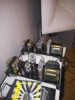
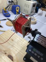
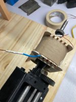
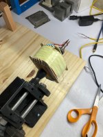
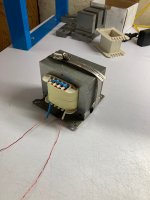
I have transformer with an 6 equivalent secondary voltage windings which are all with 4 wires parallel, diameter 2mm, all of these 6 windings provide equivalent 19Vac, with a power of about 2.5kVA (big toroidal transformer), so the transformer also allows a fairly large current.
The plan is to use it in the March 1990 issue of Radio Electronics https://archive.org/details/radio_electronics_1990-03 on pages 31 to 34 and page 69 in a "modification" of this power supply described by Reinhard Metz.

But since my transformer can provide significantly higher secondary voltage, I have given up on idea of using the LM317HVK high-voltage stabilizer.

Because I have an LR8N3-G adjustable voltage stabilizer that I would like to use because it technically meets the voltage requirements, - if it can be used?
(datasheet: https://ww1.microchip.com/downloads/en/DeviceDoc/20005399B.pdf )

Also I have 24 PNP-bipolar power transistors 2SA1962, 230V/15A to stabilize current, (datasheet: https://toshiba.semicon-storage.com...et_en_20131101.pdf?did=20429&prodName=2SA1962 )

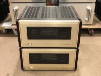
There is a suitable 6 rack unit case which rear wall is almost entirely huge heatsink, the total area of the heatsink is about 25.000cm2 (close to 4000 sq.in) so it shouldn't be a problem to exchange lot of heat, generated during the stabilization in the worst case in linear mode?

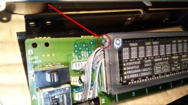
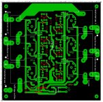
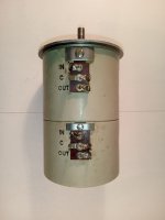
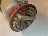
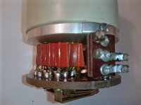
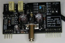
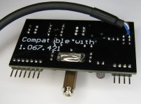
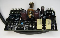
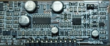
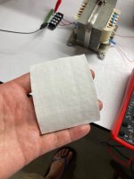
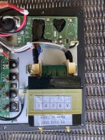
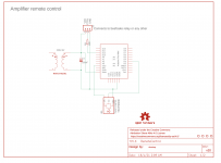
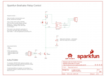
Provided that I use power transformer step switching (for this there is a step switch with power relays, (picture of transformer secondary tap switching circuit board drawing is attached), unfortunately I do not have a tap-switching circuit diagram to provide, because it is drawn by hand on paper, but its working principle is quite simple - the output voltage from output of the power stabilizer controls tap switching relays as needed, switching them on and off in series, at least the 1st secondary winding of the transformer is always switched on and when the output voltage is increased above the value set by the zener regulator, the next winding is switched in series and so on, as the voltage decreases, it is switched off in the same way and excessive secondary windings, it allows to reduce the maximum losses during linear stabilization.

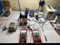
This part has been tested and works, but the power supply stabilizer (described also here: http://www.a-and-t-labs.com/K2_Lab_Power_Supply/ ) itself, which deals voltage and current regulation, gives me a headache. Since the maximum input voltages I use are about 3 times higher than those given in the referenced circuit, this would require changing circuitry - unfortunately, I'm a hobbyist and not strong in theory, so I'm in trouble and can't move forward with it.

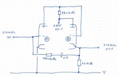
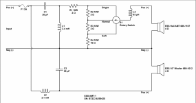
The D3, D4 stabilitrons (from this circuit here: http://www.a-and-t-labs.com/K2_Lab_Power_Supply/powersupply_ckt_layout.pdf ) that track supply voltage of IC2 LF357 obviously need to be replaced, but have I confused myself or do I not understand starting point - on the basis of which I determine their stabilization voltages? Also R6, R7, R8 - I couldn't find an explanation of these elements in the article.
I have a power supply built according to this circuit and it has proven itself over about a decade of use without any errors. So I have taken this circuit (for some reason?) as an possible solution.

I don't object if the experts think that this is not a very good solution, but would someone please guide me in my questions, which I am having trouble with.
Or if someone can offer me a better solution, say 0...10 (not exactly strictly needed "0" but say also from 10Vdc is good) to 120VDC adjustable, current limiting PSU (however, I don't want to acquire exotic parts, it is also 100% important that I can use the existing power transformer and as a current stabilizer it would be best also if I can use existing PNP bipolar transistors - otherwise I am open to other options for such a power supply I could perhaps do it with less brain gymnastics).

I have looked in some service manuals of older, higher voltage regulated laboratory power supplies (for example by HP) but they are all based on primary side SCR circuitry and quite different in stabilization stage - could someone shed some light on me, why the use of an SCR preregulator is so preferred? Is it possible that my 6-stage switching method I designed is not a good solution? I don't need extremely high reliability compared to a well-known manufacturer's device, I just need a stabilized, current-limiting power supply with a relatively large adjustment range and higher current, also which I can built at home at the end of my knee, even with the hobbyist's limited resources (to ~200 euros+all existing components) in mind.

In existing parts:
1. Power transformer: 2.5kVA with 6 equal, 19V sec. windings, each consists 4 wires in parallel, 2mm diameter - so, good current capacity
2. I also have a 27000uF/200V capacitor bank as a power filter.
3. 100A bridge rectifier (4 stud mountable 1200V diodes with hardware),
all the necessary passive components for use in the referenced schematic ( http://www.a-and-t-labs.com/K2_Lab_Power_Supply/powersupply_ckt_layout.pdf )

additional:
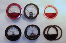
*digital panel amps (for input AC and output DC) and voltmeters,
*power transformer inrush soft start circuitry,
*probably ~90% or more of the referenced schematic elements.

Once again, I note that I have built the referred 0-50V and about 0-10A output current capability power supply 100% independently (since making of printed circuit board+100% build by only my hands), but to obtain a higher voltage, I feel that my theoretical knowledge leaves me in trouble, so I am asking for helpful guidance from the experts here.
I apologize if my request for help is stupid, I also apologize for the typos. I don't write english in my native.
Thanks for any help!

Attachments

  • transformer tap switch.jpg
    transformer tap switch.jpg
    200.9 KB · Views: 139

Circuit with good specs as a starting point

Found this circuit in an old Philips publication. It was intended as an amplifier stage for an audio oscillator but it looks like it could be used as the basis of a reasonably good audio amplifier. Cascoded long tailed pair input stage with current source in the cathode circuit. Second stage has an unused anode just begging to be used as a push pull source. Distortion figures look pretty good.

Attachments

  • Like
Reactions: astouffer

Denon POA-2400 Trouble shooting and Parts.

I cant find a good repair shop and "I am thinking of trying to fix" my 2 amps that are starting to crackle and pop even with no load on them.
I am ok/good at repairing simple electronics, real good at soldering, measuring with instructional Guidant's.

POA-2400 2ch
POA-6600a monoblock

On the 6600a I first was thinking it was CAPs going. So I did a lookup for replacements and couldn't find exact replacements for the big 10,000uf ones but I found some close / hopefully better replacements, So I think..
Here is the Info for others-hope it helps..
Original was Nippon chemi-con: 90volt 10,000uf 85deg temp, tolerance? Rated ripple (Arms) ? 50.8x82.55mm or 2inchx3.25inch.
New Cap Nichicon Grade TYPE-2: 100volt 10,000uf 85deg temp, Tolerance: 20% Rated ripple (Arms) = 6.90 50 × 100mm or 1.95x3.9inch Part # LKG2A103MKZ

But then I wondered could it be the IC or other chips but upon looking them up I cant find those exact ones or equal replacements.
Toshiba TLB521-1-BL / Optically Coupled Isolators, I can find TLB521-GB and other variances but the BL seems to have special ELECTRICAL CHARACTERISTICS 200min%-600max% and I cant find it anywhere.
Mitsubishi M5238P / DUAL LOW NOISE JFET INPUT OPERATIONAL AMPLIFIERS 8 PIN DIP, I can find it but not sure if they are legit suppliers.
Mitsubishi M5238P or NJM-082DT/BD JRC or NJM-2068DA JRC, I haven't tried to lookup yet
Hitachi HD14001BP / Quadruple 2 Input NOR GATE, I haven't tried to lookup yet..


  • If you think I really need a scope to do this and if you know of a inexpensive one, please suggest. just for amp repair.
  • Any idea's a good source to find chips with exact same spec. without hrs/days of searching? no eBay or Alibaba ect..
  • Any idea's how to find exact problem. I have multimeters but don't have an oscilloscope.

Thanks!

Compact PA - in a car handled by a single man.

We are running a small outdoor festival with a 6x4 m stage. Since the area is surrounded by walls from three sides, a relatively low power PA is sufficient. In the four years, the sound guys had the following:

1. KV2 top + sub (looked like bandpass), all active. One of the subs burned during the show, a single one was actually still sufficient

2. HK Audio Actor system with 1 sub - this was a bit on the edge, but still passable.

The sound guy using these came in a Mitsubishi Pajero with 4 active monitors.

3. A homemade PA system, biamped - bass and tops had a separate amp. This one needed to be on a small trailer - but I liked especially the bass boxes - simple bass reflex with Celestion FTR15-4080FD - a single pair was sufficient even with the non-ideal placement (one on each side more or less). Last year it was with two other subs, but it worked this year really well without them.

This lead me to an idea - today, amp power is relatively cheap and class D amps are not too heavy. What would it take to build a relatively compact, light (neodymium speakers) and not too expensive three way system with great performance? The contitions are the main PA must fit into a larger car or a small trailer and all the boxes must be as light as possible to be easily handled by one man. Any inspiration from your systems would be appreciated🙂

Recently, these boxes were linked in a thread here: Soundgear - Speakers - Amplifiers - DSP - these with a sub would probably work if the dispersion was not as narrow. Also, these would be too complicated to build.

I would think a 15" BR sub, with a 12"(15") + 2" top could be great.

For an even more compact solution, if the sub could play up to ca 400 Hz, the RCF H6000 8" horn + a 1" driver could maybe work as well - a sort of passive RCF 6001 split into two boxes with the low part playing a bit lower.

Or are my ideas completely off the limits?

I 've got some huge bass and midbass horns, but these need a large van to transport - but I would be willing to do a bit of compromise between the efficiency and sound quality and smaller dimensions - for smaller venues like the one described.

Attachments

  • SmallPAOverview.jpg
    SmallPAOverview.jpg
    168.2 KB · Views: 609
  • SmallPAv2.jpg
    SmallPAv2.jpg
    22.3 KB · Views: 656
  • SmallPAv3-2.jpg
    SmallPAv3-2.jpg
    14.6 KB · Views: 599
  • SmallPAv3-3.jpg
    SmallPAv3-3.jpg
    20.7 KB · Views: 586
  • SmallPAMidTop3.jpg
    SmallPAMidTop3.jpg
    166.8 KB · Views: 599

Beyond what frequency range CTC distance becomes a non issue?

I am in the process of building an active 4 way.

Below and above what frequencies does the human ear become less sensitive to lobing?

In a 4 way, it is very difficult to mate the upper mid driver and the tweeter.

If lobing is unavoidable, then perhaps making it symmetrical (MTM) is preferable.

Alternatively, can we move the MT crossover point higher and use a narrow dispersion tweeter instead. This would make the lobing worse, but is there a critical frequency beyond which lobing is not audible any more.

Same Q for the bass -midbass crossover point.

FS: Few different itmes - NEC relays, Meters, Caps, Cam, Cable

FS: Few different items - C relays, Meters, Caps, Cam, Cable

Up for sale few different items, selling of which separately has no big sense considering single way to accept payment and price of each item/shipping, but which can be combined to each other to increase sense of deal, or with adding to other our more expensive items how :


So, items :

1. Meters

Meters Marion, 2 inch, hermetized, glass soldered to body (but can be desolded with skill).
2pcs - 100mA, 500mA - red overlay - 20,-eur
2pcs - 30 microamperes, 50 microamperes - black overlay - 20,-eur

Meters - Google Drive
----

----
2. Mintron 1/3 CCD cam, chip board.
Model: Mintron MTV-53KS80AHP, PAL version
Sensor: 1/3 CCD
CCD total pixels : 798х584
Min illumination : 0.8LUX/F1.2/5600K
Resolution : 470TVL, 580TVL enhanced
WB range 3200-10K
S/N ratio : 52dBmin/60dB typ
Electronic shutter : AES 1/60-1/120,000sec, FIX 1/60-1/10000
Operation temp : -20C +50C
Power Supply : 12VDC 150mA
Board size 42x42, tallnes 40 with optic

Also possible additional optics.

https://drive.google.com/drive/folders/1SsurzsJuXb8Vtmmz9wOS9nuiXolO_OnU?usp=sharinghttp://

2 pcs on stock, 40,-eur each cam
----


3. Elelctrolytical caps 80-100uf, 400uf, 500uf & 50-450VDC, mostly for tube devices.

General Electric caps, Mallory, Planet Lyticap, Sprague, Cornel Dubilier, AeroVox.
Set 1 - 8pcs - 25,-eur
Set 2 - 9pcs- 20,-eur SOLD XXX
Set 3 - 14pcs - 20,-eur SOLD XXX

See more detail pics and specs in archive >> :
https://drive.google.com/drive/folders/1upKhx2wZvHdH9QbqPIgjw1X_8yfh-sYk?usp=sharing
----

4. High voltage mica caps, USA vintage, 1-5kV, AeroVox, Sprague, Sangamo, Cornel Dubilier
https://drive.google.com/drive/folders/1R5QWZqao1L086c-G1JgnnYNoVNKvjgo5?usp=sharing

21pcs - 15,-eur

----

Attachments

  • Копия DSC02926.jpg
    Копия DSC02926.jpg
    518.2 KB · Views: 1,277
  • DSC02846.jpg
    DSC02846.jpg
    545.7 KB · Views: 1,263
  • Cam2.JPG
    Cam2.JPG
    834.9 KB · Views: 1,235
  • Marion meters.jpg
    Marion meters.jpg
    238.3 KB · Views: 469

FS: Set of 7 excellent vintage attenuators Daven Shalco Langevin Clarostat

89,-eur
FREE
shipping across EU/UK

Up for sale last vintage attenuator, USA made.
Other 8pcs were sold.

So:

Daven Shalco 520-5C1, 600 Ohm, 0.75W, dual channel, 21 step (incl 0dB)

Attenuation :
- 10dB/0.5db - 1pc

Big, Dia - 65mm, Lenght - 100mm (with no shaft), fastening with two bolts through scale.

Questions, info, more pics on request, any time.

Pieces will be packed carefully with international tracking across all distance.

Sending from Ukraine. PayPal possible, in some way.

FREE shipping across EU/UK


---
See also other our items:

FS: Set of 4+ excellent UTC transformers A-22, Northern Electric

FS: Few different items - Meters, Caps, Cam, Cable

Attachments

  • IMG_20220924_022512.jpg
    IMG_20220924_022512.jpg
    181.7 KB · Views: 103
  • IMG_20220924_022541.jpg
    IMG_20220924_022541.jpg
    178.6 KB · Views: 100
  • IMG_20220924_022727.jpg
    IMG_20220924_022727.jpg
    137 KB · Views: 98
  • IMG_20220924_023012.jpg
    IMG_20220924_023012.jpg
    226.7 KB · Views: 99
  • IMG_20220924_023053.jpg
    IMG_20220924_023053.jpg
    232.9 KB · Views: 107

dipole woofers for Maggies

I tried this post in the audio asylum. Got lots of agreement, but not specific plans. Maybe you DIY'ers have tried this and would be willing to share your ideas. I have tried several subwoofers to give more "punch" to my Maggie 20.1 system, but all have been of the closed box design--ported or sealed--and I could never get them to integrate well with my planars. Didn't really get more "punch" either. Right now, I am biamping my Maggies and the sound I am getting now is the best yet. But I would STILL LIKE A MORE DYNAMIC BASS. So, maybe I'm going at it wrong. How about an OB design with six 8" woofers per side to be placed alongside the Maggies. This would make the Maggies act like "wings," thus extending the bass. Also, an OB array should mimic the way the planars launch a wave front, possiby lending more coherence to the overall sound. Has anyone done this? Can you recommend drivers, xover, etc. ?
Thanks,
Chuck

another 3way build with Dynaudio drivers

it's been a long time i have not DIY anything in my audio chain, this covid and WFH make me lazy.

anyway just started with 3way bass reflex with drivers used : Dynaudio 24W100, MW152 and Satori TW29RN

I wanted full Dyn drivers, already got MD100 but compared to Satori it's different class. so back to Satori, my candidate someday maybe MD130 but can't find it yet

mid + tw will be passive xo which i hope can get simple xo without too much parts used.
while woofer + mid will use minidsp 2x4HD

woofer will be in bass reflex around 40L volume, while mid will have 4L.

this will be my 1st build with measurement using UMIK-1, for sure I'll need all of your suggestions later once i finished the woodworking especially on how to analyze measurement results

Attachments

  • P_20220705_102724.jpg
    P_20220705_102724.jpg
    396.7 KB · Views: 488
  • 3Way Hailey.jpg
    3Way Hailey.jpg
    58.5 KB · Views: 381

crossover inductors: frequency dependent inductance

I measured the inductance of different inductors and found a rather high dependence on frequency in some cases. With my LCR bridge I can only measure @ 1kHz and 10 kHz but from my woofers response I can see that it extrapolates to lower frequencies as well. Especially one EI-cored foil indcutor stood out with a delta of 20% difference between 1 and 10kHz.

From what I have read: In case of cored inductors this has mostly to do with the frequency dependend magnetic susceptibility of the core material used. With air inductors some claim skin effect and or parasitic capacitance.

From the limited data I have gathered it seems the nominal inductance manufacturers print on their cored inductors are rather a ballpark figure as neither the frequency the measurement was taken at nor any non-linearities are usually specified. In practical terms this would mean that I have to change windings or the core gap to get the desired result especially with inductors that use a lot of core material.

nominal value /mHInductance @ 1kHz / mHInductance @ 10kHz / mHDelta / %
Air coil: Wire
0,75​
0,756​
0,695​
8​
Air coil: Foil
0,47​
0,47​
0,455​
3​
E-core (laminated ferrosilicon): Wire
4,7​
4,427​
4,069​
8​
EI-core (laminated ferrosilicon): Foil
6,8​
7,5​
6,1​
19​

Is this a known fact or am I totally wrong somehow?
Many thanks for your comments .
Ozo

Need ideas re. local feedback in old school PP amp.

Good evening. I finally have my 807 PP class A2 monoblocks operational. They started out as an attempt to build something useful from a pair of old Philips EL6400 PA amps, several iterations later they have evolved into something completely different using only the same mains and output transformers.
The circuit is somewhat inspired by Altec 1570, where the output tubes are driven by a pair of cathode followers loaded by a center tapped choke. Where Altec used a two 6W6s to push a pair of 811s, I got away with using the smaller pentode sections of ECL84/6DX8 to drive my 807 deep into class A2. The triode sections (~1/2 12AT7) are used as an LTP input stage.
Please ignore the abscense of grid stoppers, protection diodes and even screen grids in the conceptual schematic, they're all there IRL. And while you're at it, please have mercy with my photography skills too... And yeah, I'll definitely get insulated top caps.

At the moment I'm running these amps with zero NFB (the output tubes are triode wired) with an open loop gain of x10, but I feel I could trade some gain against higher DF.
GNFB from the output to the unused input of the LTP would be the most obvious method, but perhaps we can come up with something more exiting?
Some kind of symmetrical feedback either from the 807 plates or the unused UL (50%) taps would be nice, though I'm aware that "Schade" feedback supposedly don't work well with triode input stages.
Perhaps changing the input stages to cascoded LTPs would make them more suitable for local feedback?

Attachments

  • 807concept.jpg
    807concept.jpg
    82.1 KB · Views: 143
  • 807pp.jpg
    807pp.jpg
    133.2 KB · Views: 137

Open baffle / dipole line array prototype

Hi there,
I've been a member in this forum for a while, but have not posted anything so far until now. So it's a bit of introducing myself as well, I guess.

Doing this with a friend of mine, we now have a prototype of an open baffle line array up and going. Inspired by speakers like Adyton's Imagic Imagic 2.0 Loudspeakers , Steinway-Lyngdorfs Concertos, and many great builds going on here (Wesayso's array, Halair's, loads of OB's: StigErik, Scorpion, The Fin etc) the goal was set to try to make an active OB line array. A sort of "Dipole Imagic".

Enough said, here are the specs/goal for the final set up:
3-way active Line array
OB/Dipole
16 Vifa TC9 (Vifa9 BN 119/8) in each speaker
Mundorf AMT dipole tweeter
OB/Ripole sub (2x12" each)
2 x Hypex as2.100d
Rough estimation of cross overs: Vifas running down to about 100-200Hz up to 4000Hz where comb filtering will start (These are 84mm cc). If the combing can be eq'ed out (which it might not?) we can leave them as they are maybe...?

So far we have a prototype running with the Vifa's, having the aim to set the midrange first.
OB_array_prototype.jpg

I've been studying Jim Griffin's and M J King's white paper's, some Linkwitz and other ob sites (+loads of forum threads...), so I'm a bit aware what we're up aginst! We did a 180x11cm baffle to mount the Vifa's in with piano hinges on the sides, then put different baffle sizes and shapes to it and listened to how these affect this array quite differently. Anything from a angled back v-frame with 45cm wings, to the single naked mounting baffle have been tested. (Please ask if you are interested i some special shape.) According to both Edge and my ears the versions with any kind of angles baffle shapes (more like a pyramid) always got the best result. Finally we have set for a flat baffle, having the array off center and angle the baffle side shapes:
Edge simulation.PNG
Having the array centered or having completely rectangular baffles gave a more "dead" sound presentation (if I may be subjective here;-)) and didn't improve soundstaging. I should also mention that the array is power tapered in a 2/4/4/6 way (but will probably be 2/3/3/4/4 because I think it's too much now).
So please now, have a look at these measurements. Made outdoors, 1,2,3 meters resp. with REW and UMIK-1.

All distances:
1-2-3m_outdoor.PNG
3m complete:
3m_outdoor.PNG
3m zoom in:
3m_outdoor_zoom.PNG
Thing is, while there is no problem to get some bass in the array despite it's an OB (according to our xover goal), the midrange where the array should excel is very strange. Some voices, double bass, flutes, some westcoast jazz can sound quite good, while strings, acoustic piano is cathastrophy: hollow, "distorted", sharp, i.e. no body to it. So far my limited knowledge of EQ/filters cannot solve this. I've tried briefly but this tendency remains whatsoever.

Now I'm finally coming to the point where are now, because all this tapering and assymetric shapes in an OB maybe are the cause of my current problems? Or shouldn't it help? Are there too many therories competeing in the same speaker?
Please help, because probably I'm missing out of something fundamental here!


Any input appreciated!

Best wishes,
Anders

PS Hope the image upload worked!

Octal socket footprint varieties

Octal sockets are very confusing to me. Using Eagle Cad with a few custom lib's My first socket was a Belton in the large footprint chassis mount, had a PCB made worked OK. Then I wanted a more generic Octal like the cheap Chinese and eBay ones for PCB mount. I grabbed a footprint from a recommended lib on this forum. Well the footprint did not match the socket, the socket was from Amazon and seemed to the "norm" at this point I didn't know whether to look for a different socket to fit, or have the PCB redone to use the sockets I have. So I found a third footprint of Octal s that looks like it will fin my PCB. I guess my question is How the heck many different sockets are there for Octal s and what is considered the norm for PC mount?

Thanks for reading this.

Alan

Hafler DH-101 Electronic Refurb

I just acquired a Hafler DH-101 (serial number 1020167) and am about to launch into a comprehensive refurbishment of the electronic components. I have no interest in doing any of the much discussed mods, nor do I want to make any alterations to the original design. I plan to change capacitor and resistor construction as is feasible (film capacitors and metal film resistors), and likely will replace the rear RCA jacks. I have verified that this unit has the DH-106 upgrade in place. However, I'm confused about two things I see on the P-4 board.

First, according to the Component Values list in the manual, C1 is a 220pF 1000V Disc capacitor. However, in the location on the actual P-4 where the layout diagram shows C1, neither channel has the capacitor present. It doesn't look like the capacitors were removed from these locations but rather there were never any capacitors in these locations to begin with. Could this be a later production run modification?

Second, in locations C2 and C11, the Component Value list and the P-4 layout diagram shows a single 10uF 3V Tantalum capacitor in these locations. However, the actual board has two 10uF Tantalum capacitors installed in series (+ to +) apparently to create a virtual non-polar Tantalum capacitor. My question is, if I were to replace these with film capacitors, what should the capacitance be? The normal formula for capacitors in series would yield 5uF for this arrangement. Or because this is a "non-polar" Tantalum, is the capacitance calculated differently? I would prefer to use is single film capacitor in these locations, but will do a direct replacement of the Tantalums with electrolytics if necessary.

Thank you for any assistance anyone can provide on these questions.

Not symmetrical analog stages for DAC - AK4493S

Dear Friends,

I'm designing a simple AK4493S DAC and I'm struggling to understand why the analog filter in datasheet uses not symmetrical values for both phases. See the image attached.
4493 analog.png


Can someone explain to me how this filter works? Also the second set of filtering elements seem to be unusual with capacitors placement and two resistors per phase.

If there are books I can buy to learn more about analogue filters like that can you link them? I would be in your debt.

Best,
Somek

Want to replicate Triangle Magellan Cello in a DIY build

Hi all

Many years ago I had a pair of Triangle Magellan Cello SW2 before personal circumstances forced sale. I’d now like to try build my own speakers to try better the Cellos. I do recall favouring the sound of the Cellos, particularly vocals.

Any publicly available designs that may replicate or better the Cellos?

I am very comfortable with carpentry work by the way.

Thanks
P.

ACP+ Pre: lack of bass on pre out

I just built an ACP+ tonight, and hooked it up to my ACA and DIY MarkAudio fullrangers. Compared to the previous pre amp, and the sound straight from source (my computer), there is a very noticeable lack of bass. Like the low notes are inaudible.

However, when I plug in headphones (66ohm Audio-Technicas), the bass comes back.

Anyone have any idea about what I may have done wrong? I checked the resistors in the pre out path, I am pretty sure they are the correct spec.

FS: Revox A700 mute / headphone PCB upgrade 1.067.420 to 1.067.421

Had to restore a Revox A700 tape recorder and it needed also upgrade of this board, so I made few more for sale. For EU buyers - price is $90 including shipping if buy directly, for non-EU - better to buy it through eBay because it pays the import taxes and all is much easier - https://www.ebay.com/itm/185563616666 . It have pre-regulator for the opamp and all other is as in the service manual for PCB 1.067.421. Item is located in Sofia, Bulgaria

Attachments

  • IMG_6873.JPG
    IMG_6873.JPG
    247.7 KB · Views: 127
  • IMG_6874.JPG
    IMG_6874.JPG
    272.6 KB · Views: 121
  • IMG_6875.JPG
    IMG_6875.JPG
    297.3 KB · Views: 116
  • IMG_6878.JPG
    IMG_6878.JPG
    194.6 KB · Views: 119

How long will movie theatres still survive?

After a long hiatus (covid pandemic mostly to blame), my wife and I decided to go and watch the newly released “Death on the Nile” at the movie theatres in our local Mall. Unfortunately, it was not the great experience we hoped for.

I must make it clear that our bad experience was due to some personal reasons. First of all, the sound levels are way way too loud. So loud, it was actually difficult to follow most of the dialogue. Secondly, it looks like movies rely more and more on shock tactics and effects like sudden ear deafening bangs and slams. Totally over the top scenes and accompanied effects. Just watching the trailers of a few upcoming feature movies was overwhelming and exhausting. Thirdly, the only other person in the whole theater sat in the row behind us and seemed to have more pleasure in indulging in heaps of popcorn, chocolates and cooldrinks, rather than enjoying the movie. I’m not a popcorn fan, and why is everybody so obsessed with popcorn at the movies anyway? Fourthly, for the price of the two tickets I could have rather bought some Aleph J boards at the diyAudio store or snake-oil speaker cables. Yes, I am getting old, and I don’t do animation movies or 3D movies.

We did enjoy the actual movie though. Not the best murder mystery we have seen, but it was good enough. However, the whole experience would have been much more pleasant in my own home where I can play the sound over my own hifi. My setup at home is not even a HT setup, but I can now understand why people invest in HT. The movie theater sound was rather horrible compared to my speakers at home. I enjoy movie music much better at home. I can actually hear the dialogue much better at home. I can control the volume at home. I have access to great refreshments at home. I don’t have to put up with other people and their quirks at home.

So, my question is really – how do movie houses (as a business) still survive? Or, for how long will they still survive if you can have a much better experience at home?
  • Like
Reactions: JMFahey

Goodmans Minister

Inherited these from my dad a few years ago and spent some time replacing the drivers and tweeters as they were knackered. (was told the drivers that were fitted at the time were Elac 8", but there were no markings and they weren't a matched pair anyway) The original tweeters were goodmans DT4 silk domes. I replaced the main drivers with a matched pair of KEF B200 SP1063A and the tweeters with a pair of Seas prestige H1280-06 22TFF tweeters. I reused the original crossovers that were there. The cabinets are 24L or 0.85cu.ft and ported with a 52x155mm port. Having read the specs on the kef drivers I've listened to them with the ports plugged. I have also tried unplugged too and found little difference. (although I've left them unplugged) Overall I find them quite pleasing to listen to, however I don't know if there are any improvements that I could make to them.

This is how they look now.
CRW_5022.jpg


The crossover AFAIK is 1st order for the LF/midrange and 2nd order for the HF. The capacitor is 4.7uF 63V. I don't yet know the value of any of the other components. (I'd rather not have to dismantle them to find out)
X-over.jpg

X-over2.jpg


I'm guessing a custom crossover for them might be better suited. If anyone can rough guess (or knows) the crossover component values can plot the response for me, that would be a great bonus.

Ellipticor-3 vs new XO

Anyone with experience with the Troels Gravesens Ellipticor-3. A few years ago there was a thread about the Ellipticor-3, but it was a bit drowned in suggestions for all sorts of other speakers. I am interested in hearing experiences if you have built this speaker. I think it is exciting that Troels Gravesen has used a Sine-cap highpass filter for tweeter. It is quite unusual for Troels Gravesen, who is usually not afraid to use capacitors also on the rather expensive end. I watched a youtube Tech Talk 15 with Danny from GR Reseach. He had it in for an update for the XO as the owner was not really satisfied. Does anyone else have experience with the XO not working well or it can be thought that the owner just have looked at the chart and guessed at the values. I think that Troels Gravesen otherwise has a reputation for being a master at XO. Danny also says that cheap components have been used, something that Gravesen doesn't seem to have a reputation for either. The 2 of the coils are not only air coils but also of the Litz type which should be the level up from ordinary air coil.

From what I have seen, both Danny and Gravesen are extremely competent loudspeaker builders. As the Ellipticor tweeter is very effective, I have thought of using it in a construction once with a sine cap filter, which does require a lot resistance in the signal so that the impedance does not go all the way down. Hope there are some more experiences 2 years ago
where someone else asked about it. But it's not a cheap kit, even if you don't add capasitors in the XO as the drivers are some of the most expensive on the market.

Hope we have kept the thread on Ellipticor-3 🙂

I rolled my own OPT. Then I made an Arch Nemesis with it.

"Why are you applying for this job again? Are you sure you want it?"

A while back I built MoFos. The idea of using the primaries of salvaged power transformers from microwave ovens as chokes came up. I briefly tested one in my MoFos, heard that it worked, and moved on. But I had collected a few of these and I was intrigued with the idea of winding my own choke on the laminations from one, so I cut one open with an angle grinder, hacked together a winding apparatus, and wound a coil. As I had no bobbin, I couldn't get my wound coil to fit back on the E-laminations and so I gave up.

Learning about current-source amplifiers as a match for full range drivers led me to Papa's exploration of the Jean Hiraga Nemesis design, first as the Arch Nemesis and later the SIT Nemesis, which paradoxically and perhaps unnecessarily pairs an output transformer with a FET. Lo and behold therein were specifications for a weird output transformer! One with a 64 ohm primary with an 8 ohm secondary, and a primary rated to 1.3A. How cool! Maybe I could make that!

I did some tiny maths. As Papa said it was a winding ratio of about 2.82:1, so I settled on 264 turns primary against 94 turns secondary, mostly as bass extension to 25Hz required about 0.4H of primary inductance based on a primary impedance of 64 ohms. A 50W capable primary at that impedance could mean 56.6V primary, that meant 3.67A on the secondary, hence 16ga secondaries and 20ga primaries. These windings would just about fit, haha, on the EI-125 laminations I salvaged from two MOTs, which were good by spec to at least 90VA at 60Hz. I then actually got brave and bothered Jack Eliano with this draft design, as he originally built Papa's OPTs and I admire him and have some of his PVA-2n's in a passive preamp, but he shared his final prototype design with me and it had different specs and anything I made with materials at hand would likely have inadequate dynamic range and bass extension. A dark art indeed! Since no one was responding to my E-I laminate purchase inquiries I decided to build my own trafo from my salvaged trash anyway.

I bought one of those cheap manual winding 'machines' & made a mount for it, as well as a mandril and some disc like adapters. I also found a pair of bobbins on ebay that would fit the laminates I had, and settled on a design that would wind half the primary, then a layer of grocery bag, then the secondary (counter-wound to the primary), another layer of grocery bag, then the second half of the primary. I opted to re-use the 16ga enameled wire from the first failed effort, kinks, scrapes and all, and bought a spool of 20ga for the primary. Set it up & started winding.

What a pain! But I got it done & strapped it together with a hose clamp with nothing gapping the E and I laminates. I measured the primary and secondary inductance, and it kinda made sense, maybe: Primary DCR = 2R1, inductance with open secondary = 213mH, inductance with shorted secondary = 0.557mH. Secondary DCR = 0R3, inductance with open primary = 26.7mH, inductance with shorted primary = 0.059mH. Maybe sloppy, but a trafo perhaps.

I didn't know how else to test it, so I dead-bugged the Figure 6 circuit of the Arch Nemesis paper using an IRFP240 pulled from a MoFo and some power resistors I had laying around, and set the gate bias using a little DC buck converter. I settled on 50R for R2, 12R for R3, 1R for R1, and gate bias of about 5V. At 45V of V+ it drew about 0.94A across R1.

To my immense surprise, the darn thing played actual music. Tinny and thin at first, but full and kinda brassy and warm later, actually a surprisingly familiar tone to me from the PVA-2n preamp and MoFo experiences. To my chagrin as I played with the gate bias and V+ the music got thin and then disappeared completely. Pressing on the OPT brought it back temporarily only for it to fade, leading me to wonder if the core was saturating due to inadequate gapping. I dismantled the trafo, put a piece of plastic insulation between the E and I laminates, powered it up and it played music again! Very cool. Can't tell you how pleased I am that my junk salvaged first-time trafo actually made music.

Will have to decide how to permanently gap and mount the laminates as the fading and tinnyness is annoying, and whether I should wind a second core to make a mate for this one. I could even use SITs! 😛

Attachments

  • IMG_7317.jpg
    IMG_7317.jpg
    491.7 KB · Views: 397
  • IMG_7323.jpg
    IMG_7323.jpg
    428.6 KB · Views: 382
  • IMG_7324.jpg
    IMG_7324.jpg
    408.4 KB · Views: 372
  • IMG_7325.jpg
    IMG_7325.jpg
    369.5 KB · Views: 354
  • IMG_7326.jpg
    IMG_7326.jpg
    428.4 KB · Views: 359
  • IMG_7333.jpg
    IMG_7333.jpg
    283.7 KB · Views: 365
  • IMG_7331.jpg
    IMG_7331.jpg
    664.7 KB · Views: 375

For Sale FS : 5 modules of LM3886x3 amplifiers

I have for sale 5 modules of LM3886x3 amplifiers. They’re roughly 150W on 8 ohms per module.

Assembled those some years ago for a 5 channel HT system. Since I upgraded to Atmos 7.4.2 setup, I no longer need them. I bought a dedicated multichannel amplifier since I needed the gain to be the same on all modules.

How about $USD + shipping for the lot?

D233ECE0-2ADF-49D3-9348-0F14D466A5B6.jpeg
1DF298A1-56D1-49C1-BD12-843AF5B708C4.jpeg
11A30D05-7DCC-4927-958C-0B8EDDFF67AD.jpeg
7935EE6B-6397-4B43-A0E7-C2B2E2CF6CE9.jpeg
A983D657-6BF0-4462-8EB2-C99C2660377F.jpeg

ESS AMT1 Crossover. What cap values should I use? So many different versions.

I'm working on a pair of ESS AMT1. One cap is a different value in each pair of speakers. It looks like there are a few versions of this crossover and I'm not sure which caps are original so I'm having trouble figuring out what the values are supposed to be.
Each speaker has two 100uf caps in series. So this position is 50uf.
The other cap is 20uf in one speaker and 16 in the other.

A couple caps are visibly shot so a recap is mandatory.

I'm finding there are many different versions of this crossover. Even a couple different iterations of this layout.
Some have a 20uF cap for the woofer, some have a 55uF cap. With a 20uF cap, the woofer crossover point is 639Hz and the tweeter crossover point is 726Hz.
With a 55uf cap the crossover point is 385Hz. Seems the crossover point the 20uF cap gives makes the most sense?

The value of the inductors are marked slightly differently than on the schematic. One is marked 3.8mH and one 2.3mH. I don't see a marking on the third but it isn't part of the same filter stages the caps are.

Anyone have ideas or additional information? Any other crossover designs for these speakers that might be better?

I'm also interested in hearing about what types of caps people have used and the results from those.

Attachments

  • ess1.PNG
    ess1.PNG
    186.5 KB · Views: 1,958

Allo.com boss 2 player alternatives?

Hi,I'm a new member and looking for advice.
My previous system now defunct was a marantz cd-67se into a nad 5020 and mission 773e speakers.
Sadly the cd player despite repeated fixes gave up the ghost a while ago and the nad amp badly needs recapping.

So for some time I've been listening on a rubbish bt player and hankering after something decent but new and hopefully not too expensive.
Then last night one of my best friends is moving and says he'll gift me his mission 770 freedom speakers.
A step up in quality over the 773e's.
So I started looking for a new amp and streamer and found the allo.com boss 2 player and the volt d+ amp.and thought that's absolutely perfect and not too pricey either

Then of course I realise it's out of stock and for all I know discontinued.
Can anyone recommend an equivalent for the boss 2 player? And or volt d+ amp? In roughly the same price point please.
I'm a total newbie to all this streaming technology. Being 55 and coming from the world of nuts and bolts.
So any help would be greatly appreciated.
I'm in the UK too. England
Thankyou.

For Sale Jay's Audio CDT2 MK3 transport, Silver (as new)

Available in a week or two, my Jay's Audio CDt2 MK3 CD transport (as new, less than a month old at the time of this posting) and not at its best yet, Jay's suggest a min of 100 hours burn in.

Comes with all original packaging and accessories. The remainder of the warrantee is transferable to the new owner, 11 months. This is a stunning sounding transport which has had many rave reviews, just google it.

52140254991_c774256969_h_d.jpg


52140493784_b767c2d713_h_d.jpg


52139234577_07a6361475_k_d.jpg


To answer the question 'why are you selling if its that good!!

yes, I bought the CDt3 Mk3.

£1950 ONO + shipping at cost and can be auditioned (Hampshire UK) by arrangement.

Analog Ethos Legendarium 2A3 SET kit

Hello all, first post!
A couple of months ago, I went looking for a 2A3 SET kit to replace my aging Paramours. I looked at all the usual suspects: Stereomour, Monamour, Elekit, etc. I didn't want to go 300b, but I did look at AudioNote kit also.
Well Analog Ethos was mentioned a few times on other forums but besides that I couldn't find any info on them other than on the website. Kind of sketchy I thought.
The Legendarium kit however, was exactly what I wanted. Sort of.
I wanted a stereo 2A3 amplifier, not integrated, mainly because I wanted to keep my preamp in the chain.
So a couple of emails later, I plunged!

Kit was delivered two weeks later, the lead time stated on the website.
All the parts are neatly packed, double boxed with lots of foam.

IMG_1532.jpg


Everything is individually bagged. No mistakes (except by me!).
Parts are all top notch, Hammond, Edcor, Vishay, Clarity, Alps, etc. Not much room for upgrades although I did purchase some gold pin Belton tube sockets (super tight!) and coupling caps.

IMG_1536.jpg


Instruction manual is pretty hefty! Also includes a section on how tubes work. What's nice about it is that it just doesn't say to solder this to that, but it also explains some of the why and what you are doing. About 90 pages!
Chassis is very nice and comes finished as opposed to say, Bottlehead. Three color choices and the exterior wood is filled and sanded for a smooth no grain look.
Top plate is also finished well, thick and no burrs on in the holes. Very nice.
Here I am about to hang the caps:

IMG_1548.jpg


One of the things I wanted was point to point wiring; least amount of stuff in the signal path and all that. The only thing about the Legendarium is the volume pot. I may bypass that later, or maybe just run my phono stage direct and lose the preamp.

IMG_1556.jpg


IMG_1557.jpg


I did change out the coupling caps to Duelunds:

IMG_1683.jpg


The Legendarium sounds great! Pretty much walks all over my old Paramours!
It comes stock with Electro Harmonix power tubes, EH drivers, and a JJ 5U4GB rectifier. I rolled them all out and run all NOS RCAs, which really make this amp sing!

As I mentioned earlier, I couldn't find any info on this kit, so I hope this post helps folks looking for more info. Perry, the owner is super nice and answers emails quickly! I did have a slight user error problem and he was right there to help. Also interesting is that the construction manual is available for downloading so you can see what you are getting into. Nothing to hide here!
Analog Ethos also has a few other kits and all of them are also available assembled.
I highly recommend! Easy to build and it sounds awesome!

Speaker Workshop - Compile new executable for Win7 and Mac.

You probably know that Speaker Workshop has been open source for a while. Speaker Workshop | Free Audio & Video software downloads at SourceForge.net .
There hasn't been much interest in modifying the source code, probably because there isn't much to fix or change. It works good.
But what I'd atleast like to see happen is the source be compiled into a more modern (Win7, Multi core) platform. And for a Mac platform as well.

Anyone here who knows and is willing to just recompile the source into an executable for a current platform and put it out there for download ?

Antek has output transformers now...

Anybody planning on buying a pair to try out? I have not the test equipment anymore to prove them but would be interested in picking up a set. Maybe I could grab a pair and send them to someone willing to run them through the ringer?

Tube Amp Parts - Output Transformers - AnTek Products Corp

We just put an offer on a house (which was accepted!!!) So once we find out how everything goes with escrow and our out of pocket expenses I may want to grab a set.

I'm particularly interested in the 5k, 15 watt unit. They are 1db down at 10khz, 3db down at 20khz. Seems plenty workable. Maybe even running 4ohms on the 8ohm tap, for 2.5k would give even better response? As it is they might be a good fit for a pair of EL86 or parallel pair of 6V6 triode connected.

DIY PSU for Hifi Berry Dac + Pro

I am looking for a recommendation on a good PSU build for my Hifiberry Dac I will be using as a Roon bridge device. In the past, I used the IFI iPower Wall wart and it sounded fine, but wanted to experiment with a new linear power supply device I could build or buy from DIYAUDIO.

A couple ideas I had:
  • Silent Switcher V3
  • Super Regulated Power supply (I have the boards already and can use one)
  • Jason Keutemann's Capmx board (I have one of these fully stuffed)

Or I can buy one fully built online, but what is the fun in that?! Any help is appreciated.

Rubber surrounds (again)

I know this has been discussed before, but of course it never quite fits your own situation 😕

I recently scored a really nice pair of Videoton Minimax II's (for those who don't know them a budget Hungarian mini speaker with 5" bass unit and 4" cone tweeter that were hugely popular in the early/mid 70's) for some reason they were really quite magical, way greater then the sum of their parts.

This pair though the rubber surrounds on the bass units has rather dried and has some cracking, not bad, I've seen way worse but I'd like to stop or at least slow any further deterioration. Apparently the amount of degradation in these particular speakers was due to the exact amount of sulphur present in the rubber used in that batch..

I was thinking of maybe coating the surround with Copydex (a flexible water based latex rubber glue) I've heard of it used for rubber seals etc to 'repair' the cracking and/or maybe silicone grease, the type used by plumbers as a lubricant to rehydrate as members seem to rate silicone quite highly, maybe after a copydex application..

Any thoughts anyone? Has anyone tried anything similar?

Smallest driver to authoritatively hit 25Hz?

I'm one of those dudes that's a 'quality over quantity' guy. For that reason, I always get annoyed at live gigs where the PA's can smash 45Hz or even 35Hz (in the better venues), but the bass drops just fall flat anywhere below that and at 25Hz, it's just flab. I'm interested in designing and small bookshelf unit (>= 0.5ft^3) that can hit flat to 25Hz with an F3 in the low 20's and F10 in the teens. It's obviously not gonna go super loud and I'll need a hefty amp to push it and I'm fine with that. I just want a solid set of office speakers that can actually play everything on the recordings without having to drag in a massive overkill sub. About the closest thing I can find is the TangBand W5-1138SMF, but even that tapers off around 30Hz in a ported unit. It'll do, I guess, but if there's a similar size (5 1/4") or smaller that can go lower in a small enclosure, I'm all ears!

Mark levinson no 26 Rustling channel

Hello! The preamp Mark Levinson no 26 rustles one channel on a black background. what could be the problem? He recently underwent preventive maintenance with replacing old capacitors with new ones, but there is still rustling at all outputs and even in mono mode only one channel rustles. What advise to check? This rustling is not particularly annoying, but I really love this preamp and I want it to work like a Swiss watch 🙂.

DIY RCA - cat5 balun help

Hi,
First off, a disclaimer: I am not well versed in electronics, so if this is a dumb question forgive me.

I want to try my hand at building some inexpensive baluns to send a line-level audio source via CAT5 from the output of one amp to another amp on the opposite side of the house (about 80-100 feet).

There are plenty of sources for these on-line but I do not wish to spend over $100 for a pair of these. Plus, I just may have the necessary parts in my "junk drawer" to cobble something together.

I've searched the forums and could not find a straight-forward answer, but did manage to determine I need a transformer to convert the impedance.

Now here comes the dumb question part:
I have a bunch of these old Radio Shack Hi-Z/Lo-Z adapters laying around (part no 274-016C). Can I yank the transformer from them and use them for this purpose? I could not find any specs on what the impedance conversion is on them is.

So to rephrase my question in pictorial:
Can I make 2 of these:
50-7725_2.jpg


out of 4 of these:
P1070688.JPG

274-016C.jpg

(plus the right connectors obviously)

Please healp with info on this subwoofer

I found this rather unique morel subwoofer on my neighbour's garage sale, well at least to me.. I never seen this kind of subwoofer with dual motor one on the back and one is on the front of the cone

I forgot to snap photos of them, but it said morel pp8

He asked USD$ 40 each (he got 2 of them). It's in excellent condition and he said he never got the chance to use them. It was intended for his car audio system back then.

Is it any good? Anyone got more info on this subwoofer?

Thx before

Can a tube amplifier output be used to drive / power anything other than a speaker or dummy load?

So while musing about attenuators, I wondered if the output of a low wattage SE amplifier could be rectified and power a dc motor or chip amp or anything ?

Not worrying about getting the perfect attenuator / re-amp or solving any specific problem.

Rather wondering how it would be done and the likelihood of any useful results.

Hey maybe I want to put wheels on my 50s mantle radio and have it drive around the room based on what music is playing.

Ok Maybe not but it might make for some interesting discussion.

Would they be enough power to move it at all or do we need to go to the shop to get more extension cords.

Doesn’t have to be too deep a technical discussion, but yes design a working solution by all means if you like.

Motor was just a thought bubble. However I would like to keep the discussion related to lower power applications.

Help to fix Mission PCM II

I have a Mission PCM II, owned since new.
Problems started a few months ago, the display would go on or off at random, but still played fine.
Then it got random about whether it would play or not - but once working it continued as long as it remained powered up.
Now the trasnport drawer will open, but won't close using the open/close or play buttons - it will close using a light finger push - and won't respond to any other buttons.
I have unplugged and checked all the internal connectors - all were clean and shiney. Also visually checked the boards for poor joints or corrosion but can't see anything obvious.

The PCB under one voltage regulator is blackened - could this be a result of the component failing? There are other signs of heating around many components, but none are black like this.

Could this failure cause the symptoms I described? Any other suggestions as to what else I should check?
I can email higher res pictures if this would help.

Thanks in advance,
Andy

Attachments

  • pcmii_lwr_boards.jpg
    pcmii_lwr_boards.jpg
    67.3 KB · Views: 722

Seas, Peerless drivers for sale

I have a set of seas drivers and Peerless sub-woofers for sale.


(2 Drivers available)
SEAS Excel W22EX-001 (E0022) 8" magnesium Cone Woofer
$185 each + shipping


=======================

SEAS Excel W15CY-001 (E0015) 5.5" magnesium Cone Woofer (SOLD)

Peerless by Tymphany XXLS-P830845 12" Nomex Cone Subwoofer 8 Ohm (SOLD)

SEAS Excel T25CF-001 (E0006) Tweeter (SOLD)

Items are in the Bay Area. Please PM if interested in direct pickup.
Can ship only within continental US.

thank you.

Attachments

  • 20201230_102521.jpg
    20201230_102521.jpg
    967.3 KB · Views: 1,512

Hafler P3000 power amp issues

Hi guys.
I have a Hafler P3000 power amp that blew the MOSFETs on one channel, quite a while ago. These are the famous 2SJ162 and 2SK1058. So I bought the exact same parts on eBay, 2 pair of each. When they arrived they didn't work, complete crap. Someone sold me fake parts. Now I ordered (and already received) the EXICON 10P20R and 10N20R replacements, they work right away. I readjusted the bias from 400 mA with EXICON ICs to 200 mA (as specified in the manual).
Now I ran into a new issue: when I connect the 2 wire link cable for bridge mode, a noise (half way between hiss and hum) comes out of the speakers. Probably some ground loop but I cannot figure out whe it is.
Another thing is that on the channel with the new ICs now the signal LED is always turned on, even with input vol turned all the way down. So there must be some signal present that is higher then the other untouched channel, but I can't hear anything.

For Sale Non-working REL Acoustics Subwoofer Amp (for parts only / as-is / repair)

SOLD!
Asking $129 per amp or $195 for both.

These amps are BAD.

They came out from REL T5 subwoofer. The amp boards have leaked caps and bad resistors (see close up photo).

I have no knowledge of fixing them.
They’re sold AS-IS/FOR PARTS/REPAIR ONLY.

I have two for sale.

You get what you see in the photos.

No returns.

Attachments

  • B89420C2-F5A5-4B98-AC28-4886D2E850B4.jpeg
    B89420C2-F5A5-4B98-AC28-4886D2E850B4.jpeg
    741.9 KB · Views: 1,115
  • 273B0953-8DF6-4F5C-87E4-0BB1CD28F5AB.jpeg
    273B0953-8DF6-4F5C-87E4-0BB1CD28F5AB.jpeg
    474 KB · Views: 807
  • 8336A408-41D2-4523-88D4-99B1C3DA6A14.jpeg
    8336A408-41D2-4523-88D4-99B1C3DA6A14.jpeg
    611 KB · Views: 639
  • 7B8B3CEC-E094-4A8D-9B2A-243080A6A96E.jpeg
    7B8B3CEC-E094-4A8D-9B2A-243080A6A96E.jpeg
    487.1 KB · Views: 527
  • F6232332-4E96-4AC9-8B7A-17DC816AE2A6.jpeg
    F6232332-4E96-4AC9-8B7A-17DC816AE2A6.jpeg
    491.9 KB · Views: 437
  • 1DDE2812-2051-42AD-BF8B-F83323B12554.jpeg
    1DDE2812-2051-42AD-BF8B-F83323B12554.jpeg
    510.8 KB · Views: 450

70s Marantz PM 550 DC with silent left channel

Hi all

Today I picked up an old Marantz integrated amplifier from someone local for £0. I'm keen to get it going and in the process hopefully learn something about audio electronics.

This is the amp:

YuKw4N7l.jpg


My starting point is as follows:

- it switches on fine.
- left channel through speaker out is completely silent. Moving balance knob to far right has no effect on the sound. Moving balance knob to far left = silence.
- when listening through the headphone out, both channels are equally loud. However when turning balance knob to the far left, once again I get silence.

Weird right?

Difficult question but realistically, have I got any hope of fixing this economically? I have very little electronics skills but am adept at domestic electricity and soldering.

There is a system 1 and a system 2, the symptoms are the same though both sets of outputs.

Here are a couple more pics...

Some caps and transistors!

adrPsWxl.jpg


Speaker terminals:

9jysdzAl.jpg

(the black wire second from bottom doesn't look too solid, but if this connection was bad it presumably wouldn't explain the headphone output issue?)

Underside of PCB:

WjUvLrcl.jpg


Thank you guys for any help you might be able to offer. I hope to be a regular and long-standing member of this fine establishment!

Paint Finish

I'm sorry if this has been covered before. The Search feature is not working for some reason.

I'm getting close to finishing my cabinets (1.24m high TWQTL) built in 18mm MDF.
These will be going in the living room, so I want a decent finish.
I can't buy wide enough veneer sheets to cover the sides, so I'm going to paint them.

My question is what is the recommended method - brush, roller or spray can? And what type of paint?
I've watched several videos, some showing brush, some showing roller, and some spray can.
They all include good preparation (filling, priming, sanding,etc.), so that's a given.
I just want an easy-to-apply method that will give me a quality finish.
I am even contemplating only coating one face at a time - the upper face. Then hopefully letting gravity smooth the wet surface out.🙄

Soundstream TA1.3000D

U2,U3 in this amp I believe are the 5 volt regulators .

I don’t know if the originals were The KIA78L,79L or the KIA7905,7805

I believe U3 is the 7905 but when measuring the voltage on the pads I get -14.58 volts on 1 of the pads . Does this mean it’s the ground pin or how Do I figure out what direction these go in the amp

Attachments

  • A4059191-06DF-43D7-956F-84EC26CFAD0B.jpeg
    A4059191-06DF-43D7-956F-84EC26CFAD0B.jpeg
    654.8 KB · Views: 68

Questions about repairing a Graham Tonearm wand

I have a Graham wand that fits the first series of his tonearms (i.e. 1.0 thru 2.2) but unfortunately it only has continuity in one channel. Has anyone had success in disassembling one of these for a re-wire? The bendix connector is epoxied into one end of the arm wand (left end in photo below). Is there a way to dissolve or soften the epoxy without destroying the bendix connector which is some sort of plastic.

Here's what the wand looks like.
DSC_6747.JPG

Aurum Cantus G2 Ribbon Replacement

So I fried one of my Aurum Cantus G2 tweeters' ribbons - not sure how - and ordered a pair from Parts Express.

The new ribbons come without installation instructions. I think I can figure out how to get them into place, and fake the tensioning, but does anybody have experience with this? Or does anyone have the elusive pdf that is no longer available through Aurum Cantus at the following (broken) link?

http://www.aurumcantus.com/aurumcantus-download/pdf/Repair Instructions for ribbons.pdf

I was able to view the first page of the PDF by using "QuickView" in Google - but is that all there is?

For those who need to do this I've posted the recovered PDF image on my Web site:

Replace Aurum Cantus G2 Ribbons | Vitrine

Should I replace the other one as well, since I have 2 (I assumed I'd screw it up the first time, and they're only $5.00)? Do ribbons age?

Any advice from those who've done this?

TIA, Than

A small sample of historic capacitors tested and compared

Following this question, I have fullfilled JP's wishes: https://www.diyaudio.com/community/...ot-your-typical-amplifier.390272/post-7122671
I have measured a number of vintage 10µ/25V capacitors. One exception is the "control", modern cap, radial of course, ROHS, miniature, 105°C and much smaller.
I have also measured a very old (1960's) cap made by Philips, but since it is 6.3V type, I measured its leakage current at 5V instead of 10V for the rest.
They have all been measured in identical conditions: I plugged them in parallel on a breadboard, with removable links to measure the current, and I fired them all at the same time, leaving them a few minutes to stabilize.
None had ever been used, and they have been rudely awakened from a sleep ranging from 2~3years for the control to 60 years for the eldest.
The ITT and Philips axials are both from the late seventies.
On this pic, the bottom one is the oldest and the top one the control:
1663272331965.png


Here are the results:

1663272382019.png


Unsurprisingly, the oldest is the worst: it has had a long time to lose its water, and has a poor esr. The ITT and Philips are very much in the same league. The more modern, radial and extremely light Philips is crap; probably the worst caps made by Philips.
The modern control has a tighter tolerance, a lower leakage (normal anyway, it didn't sit for decades on a shelf), but a higher esr, probably due to the higher temperature rating and the higher resistivity electrolyte
  • Like
Reactions: dreamth and Pano

Arduino Based Remote Control

Hello all,
I am constructing an arduino based remote control for audio equipment.
I will post the progress here.
It is based on simple equipment you can find easily.

The remote control I am using has three main Functions (A, B, C).
A will be for the amplifier, B for the preamp and C for a source like a DAC.

For the moment there is only code and schematics for powering on and off. So you have to press A, B or C depending your choise and then you can press the power to power on and off.

The code puts arduino to sleep in order to use as less power as possible and uses interrupts to wake up. So when the equipment is shut down it is really on a standy mode.

The arduino is always on the main power and uses a relay to open and close the equipment.
You can further check the repo and the pdf with the schematics
GitHub - nkostop/amplifier-remote-control

I welcome any suggestions!

Attachments

  • 524c5cf4757b7fe9068b4568.png
    524c5cf4757b7fe9068b4568.png
    204.5 KB · Views: 230
  • Screenshot 2021-04-18 at 2.37.02 AM.png
    Screenshot 2021-04-18 at 2.37.02 AM.png
    231.7 KB · Views: 211
  • Screenshot 2021-04-18 at 2.37.07 AM.png
    Screenshot 2021-04-18 at 2.37.07 AM.png
    352.8 KB · Views: 209

Help with DCS 205

Hello,

Not sure this is in the right forum : I have a pb with a DCS205-4 as part of a WAW speaker.

The sub part is 11 liters closed. Microphone is a calibrated UMIK, source is a macbook, pre-amp is direct (Marantz) and AMP is a Gremlin (T-AMP) running on 36V. I don't have problems with other speakers using the same chain.

The problem is that the response has nothing to do with the specs nor closed box simulations:
DCS205-response-in-box.png


There are huge peaks around 750Hz and 2k
So I tried to measure the baffle only w/o the box :
DCS205-response-on-baffle-865x325mm.png


The peaks > 600Hz are still there. So I did measure the speaker alone, magnet on some absorbing material, cone facing up, mike on top of it (maybe not the best, but that was to get a rough idea):
DCS205-response-alone-flat-on-ground.png


And even if measurement conditions here are really bad, the peaks are still there (BTW it's the second driver, so they are all the same)

The problem is that i'd like to go passive first order, and here I'm stuck with using bi-amping and a dsp.

What am I missing ?
Projects by fanatics, for fanatics
Get answers and advice for everyone wanting to learn the art of audio.
Join the Community
507,849
Members
7,890,568
Messages

Filter

Forum Statistics

Threads
406,365
Messages
7,890,568
Members
507,849
Latest member
Jean Basile