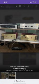
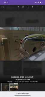
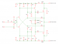
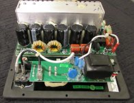
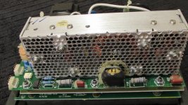
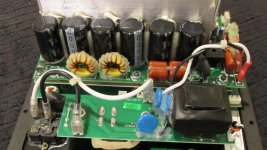
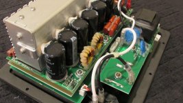
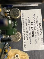
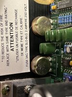
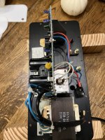
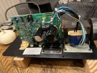
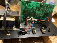
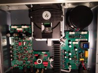
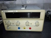
Zapco 9.0XD

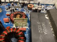
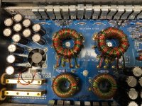
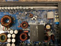
This amp has a strange issue .

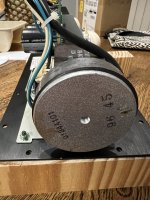
It will work fine for 20 mins then it will start drawing excessive current and the resistor will start smoking.

Leave the amp sit and it will work fine again and then if I turn the amp off and back on it will draw current it’s hit or miss with this amp .

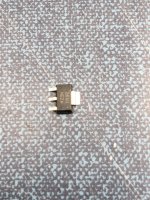
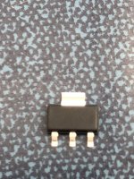
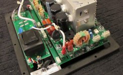
As seen in picture 3 this is the resistor that starts smoking .

Any ideas on what to check or what may be causing the issue ?

The amp has been worked on before by someone else .

Attachments

  • 475626FE-D801-4047-942D-C96AB4FE84B0.jpg
    475626FE-D801-4047-942D-C96AB4FE84B0.jpg
    1.1 MB · Views: 169
  • 46078462-00E2-4DBC-A6C3-02F1C9865C5B.jpg
    46078462-00E2-4DBC-A6C3-02F1C9865C5B.jpg
    1.1 MB · Views: 163
  • DAF5B86E-1192-4809-B6E6-5D6A6D8BA94B.jpg
    DAF5B86E-1192-4809-B6E6-5D6A6D8BA94B.jpg
    994 KB · Views: 140

FS: Three Hammond 278CX power transformers

Two of these 278CX have nice looking end-bells, the third transformer
has a 1/4" or so crease in one end bell and came that way
new.

They were only run a couple of hours each with 1N4007
recification, cap input filter and a dummy load, having a recified voltage of
about 585VDC with a 3K load.

They are not dead quiet - just the nature of that Hammond unit.
I built a punchy bass guitar amp with another 278CX and 4-6550. Rubber mounting washers might be a good idea.

$58 each including priority shipping for the two with nice end
bells.


$53 including priority
for the dinged unit

Paypal works best


Unit 1
M92mFEA.jpg


Unit 2
lckBujs.jpg


Unit 3
ECEGoDo.jpg


Unit 3's ding (not as deep as it looks)
2uXy5CA.jpg

6SN7 LTP and CSS Question

Hi,

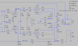
Is it possible to use 10M45S as cathode current source in 6SN7 LTP shown on schematic? From simulation it appears that cathode bias voltage is only about 10V and I don't know for sure if this is enough for depleted mode mosfet.
Another option is a 10mA constant current (limiting current) diode like LM334Z (40V/400mW max, which seems enough). Currently have no data how LM334Z (which was designed for power supplies) will behave in audio circuits.

Thanks in advance for any suggestion(s).

Attachments

  • Screenshot at 2022-10-01 16-27-11.png
    Screenshot at 2022-10-01 16-27-11.png
    25.6 KB · Views: 238

L&D model# LD-D105H Floorspeakers?

I found these speakers at the local recyclers,got em for $10,they looked OK and just needed new woofer surrounds,I picked up a NAD 7020e receiver at the same time for $15. After a good cleaning pots ect... I tweaked the bias and DC offset and hooked the L&D speakers up.Well Id say my jaw hit the ground and bounced! What an excellent combination,I couldn't believe how good they sounded, this would be the best system Ive come up with yet(sonically),beautiful effortless highs,mid-range and bass.Id like to know more about these speakers but I cant find anything about them except they are made in Australia by Jorlen Audio industries PTY LTD. On the back is a sticker that says.System; 10", 3 way, 3 speakers. Frequency; 45hz-18000hz. Power;35 Watts RMS. Impedance; 8 ohms. They have Plessey shielded horn tweeters and 4 and a half inch Plessey shielded mid-range. I was expecting to see a sophisticated crossover but when I looked it was just a few capacitors? But nevertheless they sound awesome, not for full on rock&roll though I suppose.Any info on these speakers would be most appreciated. P.S I tried these speakers on a Sansui AU11000 amplifier,same deal awesome!!! Redrooster.

Volunteer Jobs

As many of you know, my beloved cat Chloe passed away five weeks ago. The grief is a daily thing and it's not doing me any favors in my quest to regain my health.

Right away I thought about getting a volunteer job at the local shelter. About ten days after her passing, I confidently applied at PAWS shelter, a short walk from my house. (I don't drive any more so wherever I go has to be close. I haven't learned yet how to ride public transportation with visual limitations and quite frankly the notion terrifies me- public transportation is full of predators and wierdos that I'm positive would try to prey on me but that's another rant.) I was upfront about my physical limitations. I also explained how I would be an enormous asset to them (which I most definitely would; I'm great with dogs and cats) and that I was motivated by the need to work with and be around animals. I know how to give a cat a shot, how to give them a pill, I know how to hydrate a sick animal subcutaneously and other vet-tech skills. I also have extensive experience babysitting dogs, cats, and birds.

To my surprise, I was summarily rejected. Too weak, too blind, too sick; they wouldn't even agree to meet me. This is a major slap in the face and quite frankly exacerbates my grief. And now I'm having anxiety about getting another cat. Will I be able to handle her? Will I get too sick or die and leave her with the problem of getting re-homed? My neighbor Dave down the street recently put his 17 year old dog down. He is so grief stricken that he is almost bedridden, but won't adopt another dog because of the same concerns.

I find it hard to accept that I'm that old an in the way. How do seniors stay happy when people summarily dismiss them as useless and stupid? I have a lot to offer and so do a lot of other seniors. My neighbor Dave is 79 and still sharp. He wrote for the Chicago Tribune for 40 years. Shall we just put him on an iceberg and shove him out in the ocean too?

FS to USA: MOTU M4 USB audio interface (free shipping!)

I am offering for sale four MOTU M4 USB audio interfaces. Two are new/unused and two have been gently used for about 1 year in my audio/loudspeaker projects. I recently bought an Ultralite mk5 to replace these great interfaces, so I would like to give them a new home. Excellent cosmetic condition on all. These have low THD+N and work perfectly under Linux (as DAC and ADC) for audio processing. Offers both balanced TRS and RCA outputs. These would also make a great measurement interface. For full details see:
https://motu.com/en-us/products/m-series/m4/

I am asking $200 each for the unused units - ONE SOLD, ONE STILL AVAILABLE.
The gently used units are $180 each.
I have the original MFG packaging for all four units.

SHIPPING IS FREE TO USA ONLY. Paypal payment. Pick up in person and pay cash if you like! I live in lower central Michigan.

Attachments

  • m4_front.png
    m4_front.png
    151 KB · Views: 128
  • m4_rear.png
    m4_rear.png
    128 KB · Views: 125

Commercial motional feedback woofer available sort of

Sony SA-W2500, saw it at Walmart for $100 but Sony says it is discontinued. This is a small box, presumably sealed, with a 10 inch "mica reinforced" cone and "motion feedback" with a 100-watt amp. Nobody seems to bother to mention basic specs like input, cross-over, controls.... and basic necessary information like that.

It seems to have the kind of voice-coil bobbin sensor coil (tactically massaged) that I believe is best way to get feedback signal. Seems to fulfill one of the oldest target goals of motional feedback R&D (going back to JAES 1954): making a smallish box do remarkable woofing.

I haven't yet found a meaningful review. But the Amazon review crowd is quite ga-ga as to value.

Anybody know about this woofer or Sony's efforts along those lines?

Ben

Speaker isolation

There are lots of very positive reports around from owners of the Townsend Seismic platforms that are used to isolate speakers. My understanding is that the isolation pods utilise a spring which is enclosed in a rubber boot which has a very small hole in the top to allow air in and out. The spring provides the vibration absorption and the boot dampens the spring movement to prevent bouncing.

These are expensive so one naturally thinks of cloning them. There are plenty of companies that make spring based feet for absorbing vibration from industrial machinery, but I haven’t yet found any that also have the rubber boot. Is anybody aware of anything similar that doesn’t have an audiophool price tag?

Mullard 3-3 Voltages

Good evening!

I have built a Mullard 3-3. But I have problems in the power supply and generally with the voltages. I'm doing a test without tubes and I have much too high voltage already at pin3 of the EZ81 ... 400v?!? (transformer has 300-0-300)

With the tubes installed the voltages are also too high. Over R13 I measured ca 60V with 150V (normally we have around 230V here in Austria) mains voltage set on my variac !?! Also the anode voltages at EL86 and EL84 are too high?! Wiring error?
The OPT has a blue 0 ohm, red 5kohm cable (info on the OPT, company Primary Windings from UK ). The 5kohm cable hangs on the anode pin7 of the EL84. The 0 Ohm Blue Cable is connected to pin 3 on the EZ81 ... Right?

EZ81 tube broken...electrolytic capacitors or resistors faulty?!
The center tap of the mains transformer is connected to the neg. Pole of the first electrolytic capacitor and from there it goes / is connected to the case and protective cable....

What am I overlooking? Shred everything out...?!

I use this schematic
https://www.heatedcathode.com/3w-si...-amplifier/model-1955-gen2-el84-se-amplifier/

QUAD ESL63 trouble

hi,

my first post and hope I will get a few pointers from you guys 😁

i am having trouble with one of my ESL63 speakers. all panels have been done by one of Australia finest, so no trouble there.

i first suspected the protection board, replaced all crucials……problem persisted.

problem is a bit tricky to accurately describe: its like a popping discharging sound that is heard at higher dynamic signals.

at this point I did not suspect a panel damage as they were all done a couple of months ago.

Next step was to change over the electronic box (foot) …the healthy speaker sounded still fine, the sick one still sick !

so, it is not a fault in the electronic part.

next I disconnects panel after panel starting with the top one but the fault persisted right down to the last panel…..😡

i inspected all panels and was no indication whatsoever of a panel problem…..which leaves basically one culprit:

the coil/capacitor boards ?!?

would this be a pausible conclusion ? I have not yet found a single post, reporting trouble or issues with that part of the speaker.

at this stage I could do with all the help I can get.

thank you guys…

Need help with computer speakers.

As some of you know, I recently got a cat. I thought my house was cat proof but she's quite energetic and frisky. Anyway, I have old "hi-fi" speakers on stands by my computer. They're great but they have to go. Kitty sits on them and has started to claw the grill cloth when they're playing. So I need the floor space back and I will put up another Kitty Condo where one speaker was. This is right by a window which is why she's so interested in it.
I'm not ruling out building a pair but I don't think I can beat these for the price. https://www.abt.com/Polk-Audio-Sign...Home-Theater-Pair-3003621400005/p/169216.html Any other recommendations are welcome. Small with clear audio, acceptable without subwoofer is the criteria. I'd consider a worthwhile design for DIY too. That price is about the top of my bracket too, but I would consider anything worthwhile.

Thanks.

Pentode's screen voltage/current

The question is, how to choose the screen grid voltage (and then, the current) for a voltage amplifier, taking into account I need the maximum amplification, and plate voltage swing, regardless on distortion issues.

Some time ago, I saw a page in where he author solve this question taking some points on the datasheet curves, and making the tube equation for a 6AU6 pentode, but I can't re-find it.

I don't want to make simulations, in fact I prefer to make the calculae in the usual manner, with pen and paper, and the tube I'll use is the pentode section of the 6BH11 compactron tube.

Many thanks in advance.

Using the TDA1512 at lower closed-loop gains

I intend to use a TDA1512 in an application where the closed loop will vary a lot, falling down to unity in some cases.
I know the usual tricks: increasing the compensation (it is external), increasing the noise gain, but although they work for small signals, the input seems unable to cope with even moderately large signals. As soon as the input signal exceeds a volt or two, all hell breaks loose.
Any idea what's causing this behaviour (the data available on the internal circuit seems scant), and the way to remedy it?

Dumb and ignorant question about low frequency directivity

I haven't seen a direct treatment of this question before, but it does seem dumb to ask, but I'm going to ask anyway.

Are frequencies <100hz omnidirectional because the wavelength at the cone is so long that the wave simply propagates in all directions due to its size?

Or, it is because low frequencies can't really be blocked by reasonable thicknesses of normal cabinet materials? It seems 16mm of solid wood is just barely good enough to get -60dB at 100hz, and it gets worse the lower you go.

Or is it both?

I'm a crazy person so I'm wondering if you could make a more cardiod-type speaker by simply making really thick concrete enclosures, or something similarly impractical. I am not sure if that would solve anything in terms of LF directivity, which is why I'm asking.

DIY 4 point pivoting arm

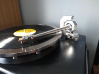
Thought I would share this latest build. The goal is to build the best possible 9" arm with materials available where I live. Before anyone says I should have used carbon fiber, I could not source CF pre-preg in less than commercial quantities so I used 6061 T6 aluminium.

The scope

Variable taper and wall thickness wand.
Rigid bearing assembly, based on Technics but on steroids. Vertical bearing housing 100x25x17mm.
Gimbal arrangement 4 point sapphire Vee jewel pivots with highly polished tool steel pins.
38mm arm post with VTA on the fly and split collet locking base.

Specs

Effective length 239.3mm
P to S 222mm
Overhang 17.3mm
Offset 23deg
11.6g vertical effective mass not including cartridge.

First pic is held together with Blu Tack to check height. The other 2 pics are with pivots complete.

Attachments

  • IMG_20210725_133246193.jpg
    IMG_20210725_133246193.jpg
    779.2 KB · Views: 911
  • IMG_20210727_140558367.jpg
    IMG_20210727_140558367.jpg
    845.2 KB · Views: 915
  • IMG_20210727_140535947.jpg
    IMG_20210727_140535947.jpg
    828.7 KB · Views: 913

Pioneer gm-x324

Hi this amp fáiled yesterday i have many years with it.
It gived a nice sound. But it do not power on. Anymore 🙁
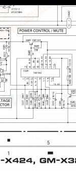
Checking it i found suspicious voltages that don't match. the voltage the service manual said must be.
The PS is not oscilating,because ta8194z do not actuvate upc494c, the TA8194z had this voltages:

1. 0v
2. 0v
3. 10.28v
4. 12.16 v
5. 0.54 v
6. 0
7. 0.25v
8. 0v
9. 0v
10. 12.1
11. 0
12. 12.16 v
13. 12.1
14. 11.64
15. 0
16. 0


The pin 4 must be near to 0v. If is 12 volts it Will not polarize the transistor and the transistor will not send 12 volts to pin 12 of the upc 494 c

I post the part of the service manual with the correct voltages the IC must have

Thanks in avance for the help

Attachments

  • Screenshot_20220827-234428_Adobe Acrobat.jpg
    Screenshot_20220827-234428_Adobe Acrobat.jpg
    166.4 KB · Views: 141

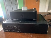
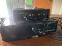
Wadia Transport & Miro ad1862 dac

Hello gentleman,
I would like to sell wadia 70i transport with pin connector Bluetooth 5.0 .you can play music by phone direct amp or DAC by spdif .
Price $70 plus shipping (SOLD )
2: firstwatt F3 pcb board already on board resistor and capictor .
Price $15
3: TDA1541 D3 and floating power supply by ranj .
Price $20. Sold
4: Miro AD1862 DAC plug and play connect power supply .( power supply not including)
Price $75. Sold

Attachments

  • 768268B6-2333-421B-9EA5-924973E709ED.jpeg
    768268B6-2333-421B-9EA5-924973E709ED.jpeg
    376 KB · Views: 196
  • 52BBF703-5B0F-4187-BE96-13777D21EAC4.jpeg
    52BBF703-5B0F-4187-BE96-13777D21EAC4.jpeg
    366 KB · Views: 170
  • B509D58A-3E20-474D-BDBC-83EB1C541D08.jpeg
    B509D58A-3E20-474D-BDBC-83EB1C541D08.jpeg
    322.5 KB · Views: 186
  • 36A0E4D6-844F-4A47-97FD-339F5CE745D6.jpeg
    36A0E4D6-844F-4A47-97FD-339F5CE745D6.jpeg
    378.7 KB · Views: 195

For Sale Acurus A200 X2 power amp . One dead channel

I bought it for a chassis mainly but it will be ages before I get to build something so it has to go and free the space . One channel works the other , which somebody repaired before is fried . Chassis is in excellent condition with oval cutoff on the front and easy to customize. There are tons of pictures online but if there is some interest I will post some pictures . $180 plus around 30 Lbs of shipping from 48212.

DMA105-4 polar FR measurements minimal baffle

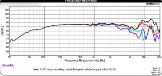
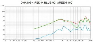
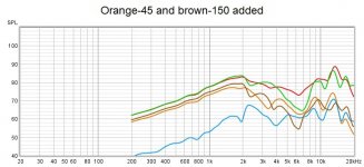
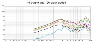
Had about an hour before work today and was curious about the polars on this driver, so I dug one out and did a quick 0-180 on a small, thin piece of flat baffle. I had experimented with it some time back on this baffle, crossed to a GRS 3.5" planar on the top end at 1800hz, and a Satori W024P-4 9.5" at 500hz on the low end, forget the slopes. It sounded excellent, but life got in the way and I had to take it apart and put it away to clear space and work on something more urgent before I got any measurements.

Turns out it is a very good driver for the 500hz to 1800hz range on a minimal open baffle, and I imagine nude. I've included the published specs for the driver also. It's a 5ms window with the sweep starting at 100hz with 6db/oct smoothing. Not sure exact distance, but less than a meter. I was in a hurry, I'll do better ones at a later date, but this showed me what I wanted to know.

Attachments

  • IMG_20220930_120844859_HDR_2.jpg
    IMG_20220930_120844859_HDR_2.jpg
    286.7 KB · Views: 248
  • IMG_20220930_120323317_HDR_2.jpg
    IMG_20220930_120323317_HDR_2.jpg
    339.1 KB · Views: 255
  • dma105 pub fr.jpg
    dma105 pub fr.jpg
    77.4 KB · Views: 268
  • dma105 0 90 180.jpg
    dma105 0 90 180.jpg
    72.7 KB · Views: 253
  • dma105 45 150.jpg
    dma105 45 150.jpg
    75.4 KB · Views: 231
  • dma105 15 120.jpg
    dma105 15 120.jpg
    78 KB · Views: 241

Metamaterial Acoustic Absorbers

I made a metamaterial enclosure for the SB Acoustics SB26 ADC, and thrilled with it's performance, started thinking about covering a wall with metamaterial absorbers.

Link to original project: https://www.diyaudio.com/forums/multi-way/380104-unity-horn-metamaterial-tweeter.html

4vQmcmt.jpg


unnURML.jpg


Vpznk7W.jpg


There have been quite a few papers written on metamaterials. I think I've read half of them and understood 10% of what I read.

IMHO, the academic papers are unnecessarily complex. Methinks this is because some of these papers were written by graduate students who were using the math and the physics to demonstrate that they'd learned math and physics.

As far as I can see, metamaterials are simply an array of closed back transmission lines.

Due to this, there are a myriad of ways to fold the array of lines. If you've built a transmission line or a tapped horn, you have a pretty good idea of how to fold a TL.

With that concept in mind, for this absorber, I largely focused on using a specific footprint and a specific range of frequencies, and then I folded the lines to use as much of the space as possible.

IE:

In prior metamaterial projects, I was using software to generate and idealized series of frequencies, and then trying to figure out how to fold the line. A lot of space was wasted.

In this project, I let the size of the object dictate the folding, and I basically used up 100% of the space inside of it.

This thing isn't perfect, it's "version 1.0"

What I am envisioning, is getting this absorber refined enough so that I could 3D print as many as 36 of them, or maybe even more. Enough so that I could cover an 8' x 2' strip along the back wall of my living room.

The way that my living room is designed, the speakers basically fire straight into the bedroom wall of my master bedroom. Which means that I can't watch movies, music or TV any later than about 9-10pm. Which is no bueno.
  • Like
Reactions: Gruesome

Mares Connoisseur 1.0/2.0 and Lyra Connoisseur 3.0 - internal Images wanted

In post #10, 1 and 13 under
呢三件野....用晒我今年嘅零用錢 ! ! ! - 兩聲道音響討論區 - Hiendy.com 影音俱樂部 - Powered by Discuz!
are to find various descriptions.
in post #25 under
Connoisseur Definitions 3.0 preamplifier - is it still among the best? | What's Best Audio and Video Forum. The Best High End Audio Forum on the planet!
and under
Lyra Connoisseur > Preamplifiers
is mentioned a so called "air-dielectric" construction - this means without PCB, maybe in the kind of this approaches for a IC power amp:
Point 2 Point (no PCB) for TDA7293, TDA7294, TDA7295, TDA7296.
or Jadis tube amp under
https://www.bluebirdmusic.com/edit/files/images/products/jadis/da88s_lrg_inside.jpg

Maybe one of the members can upload pictures from inside of the mentioned models - thank you very much.

On the web there are only internal images from this newer PCB version:
Lyra Connoisseur 4-2L SE: What a masterpiece!

Attachments

  • Connoisseur.jpg
    Connoisseur.jpg
    559.3 KB · Views: 291

Another Improved Array - Sep 2022

For the last couple of years I've been trying to come up with a loudspeaker design that provides a balance between "spaciousness" and "pinpoint imaging."

I've owned a bunch of speakers over the last 15 years:

1) Gedlee Summas: Incredibly dynamic and smooth, but not as "spacious" as a conventional speaker. This was due to the 90 degree waveguide, I think.

2) Vandersteen 2CEs: spacious but not dynamic at all. Basically the opposite of the Summas

3) Bill Waslo Cosynes: Similar in sound to the Summas, soundstage depth and intelligibility were improved I think, but dynamics were limited by the use of small midranges

This isn't a criticism of any of these three speakers, just a reflection that I think I prefer something less "pinpoint" and more "spacious."

I've made a bunch of threads lamenting this for 2+ years now, and I think I may have stumbled on a new type of array, so thought I'd share it here.

s7t-pair18-jpg.47746


snallxa135377.jpg


Zj4aQwG.jpg


I think that the "ideal" array might look a lot like the WMTMW arrays from Perlisten, Dave Smith, John Dunlavy, etc. Basically they provide wide horizontal beamwidth and narrow vertical beamwidth.

I've never built a speaker like those, because the cost and complexity of the passive crossover gives me pause. The crossover on the Snell speaker would probably cost $200 per side these days, if not more.

I've been following Dave Smith's thread on arrays, but I've struggled to come up with a line array that performs well with a single driver. And when I try and use two drivers, the passive crossover gets hideously complex and expensive.

I came up with something new that seems to work much better than I could imagine...

Force of 1/2, please pm me

Hello John (@force of 1/2 ). We’ve been messaging over on the other forum (presuming you’re the same guy) about a small group buy of PCBs for Wyn Palmer’s phono preamp. I’m currently unable to access my account there, and the mods are unresponsive. Please PM me here if you can (I’m still in moderation so can’t start a conversation). Don’t want to leave you hanging in the group buy!

-Aaron

about Studer A730 next track function problem.

Hi.
I receive a studer A730 from a friend.
It works very well but the 'next track' function not works.
from the manual ,I see the Cursor button could offer the function of next track during playing.
But I press the Cursor button , it does not jump to next track...
I am sure the cursor button works in cursor function ( when sets cue , it works well as a cursor).

It is very very thankful that someone give me some suggestion about the problem.
many many thanks!
Kindest regards.

mono signal?

Hi I am having trouble with some active midrange through a mosconi dsp. All my other channels I click on left or right, but with these mid range it seems to play a mono signal either left or right.
One speaker distorts when playing frequency set to below 300hz also, so am guessing is damaged.
Any ideas appreciated.

Need help. Strange sine wave on outputs.

I have a TSE 300b amplifier which has suddenly started to sound bad. In the attached image you can see that I have measured the output, and there is clearly something wrong.

I have measured the signal at the following places in the amplifier:

1. Signal on RCA input = ok
2. Signal just before the input tube = ok
3. Signal after the coupling cap = ok
4. Signal after output transformer = BAD (attached image)

Could this be due to a bad filament regulator (Sharp PQ5EV5 voltage regulator) or the STPS30L30CT dual schottky rectifier?


TSE output.jpg

Some days the Dragon Wins

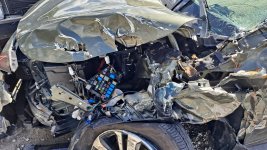
I had a minor, well maybe not, incident recently. A person with a revoked driver's license, no insurance and a BAC way over the limit passed out and drifted into my lane on a two lane road. I was doing 40MPH (63KPH) and he was probably above that. That is a closure rate of 120 feet per second or 36.6M/s. I realized at about 60 feet that he was coming into my lane. That gave me probably 500ms to react. You don't have time to think. I spun the wheel to the right lock and hit the brakes hard. BOOM! I am in a lot of pain, but nothing is broken. The car (2019 Subaru Outback 3.6R Limited) is a write off.

Witnesses identified the driver who left the scene smelled of alcohol and was staggering as he walked away. I found a previous on him for driving with a revoked license, no Ins, driving infraction from 2006 . Repeate offender.

The car did what it was supposed to, protect the passengers. It looked like someone lifted the hood, dropped a frag grenade in and dropped the hood.

I ordered a replacement today. It will arrive around the end of Nov. The cost after ins settlement for uninsured motorist is well worth the vehicle.

Attachments

  • 20220926_131719.jpg
    20220926_131719.jpg
    669.1 KB · Views: 148
  • 20220926_132555.jpg
    20220926_132555.jpg
    557.2 KB · Views: 146

'Smart Negative Feedback' - Second order low frequency roll-off (Global) negative feedback

Hi all,

Hoping for some guidance with applying the principles presented in the is web page http://www.valveradio.net/audio/smart-negative-feedback.html to a SE guitar amp. Its worth reading the whole article and the associated links.

While the author intends the application for small SE mantle radio, which may often have a grounded cathode / grid leak bias driver I would like to apply the approach to a cathode biased driver. The benefits described in the article would appear to be helpful for a typical single ended 6v6 or el84 guitar amplifier.

I have implemented the circuit ( with small changes based on parts on hand) both for a grounded cathode / grid leak and a cathode biased driver.
However want to understand if how it is best applied to a cathode biased driver stage.


LF-and-HF-feedback.jpg


My main concern is how to size a shunt resistor , or if it is preferable to apply the feedback to the top of the cathode resistor with out shunt resistor ?
This would involve the recalculation of the filters, which I'm struggling with.

One option is to setup a pair of dual gang 25k pots for both the nfb R8 / R9 and the R6 / R7 and tune it by ear. Then move the nfb point between the different application points and test again to see what works best. This may mean that the caps are sized correctly for one application point but not others.

I have added a 25k pot in parallel fixed resistor values to test this approach to the but find the the 25k pot is so sensitive at the low end that minor adjustments are difficult.

While this is not HiFi and does not need precise calculation or measurement I would like to ensure I'm heading in the right direction in a practical sense.
I do greatly appreciate the author's work and the many very experienced and expert contributors on this forum.

Hoping for your kind assistance.

ADCs and DACs for audio instrumentation applications

Actually there are real considerations for the audio market that are different other that the elusive "sound". SNR or dynamic range in the audio band. A weights noise. THD which is related but not identical to DNL or INL. At the same time adding a lot of overhead to using an ADC (external interface logic, filtering etc.) would need justification if the primary requirements are not substantially better. SAR ADC's have a lot of interesting applications and the separation of the sampling rate from basic function can be really helpful in specific applications but audio will have very constant predictable sample rates etc. and the additional flexibility is not a benefit.

All audio grade ADCs, PCM4222, AK5572, CS5381, etc... have the (in my opinion) big issue of a sharp increase of the noise floor at high frequencies, making for example low distortion measurements @20KHz practically impossible. These noise humps root causes are well understood and very difficult to avoid in sigma-delta converters. I myself do not believe in the relevance of distortions @1KHz for the overall amplifier quality, so I consider audio measurements @20KHz critical.

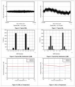
Otherwise, I don't see in audio grade ADCs the DNL and INL (and in general any linearity metric) seriously characterized (other than a chart with a straight line), compare with the datasheet for a 20bit SAR (see attached). SNR and dynamic range in the audio band are related to the number of bits (and there are SARs up to 32bit, sacrificing the distortion performance for SNR and DR, but 20bit seems to be kind of sweet spot today).

Again, I don't preach any SAR for audio applications - but for audio instrumentation purposes they appears to me as a much better option than audio ADCs. Again, audio grade ADCs are simply not specified for instrumentation (and rightfully so, since this is not what they are designed for, as much as industrial grade SARs don't specify for example the A-weighted noise).

Attachments

  • Untitled.jpg
    Untitled.jpg
    312.1 KB · Views: 2,334

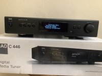
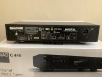
For Sale FS: NAD C446 tuner. AM/FM/Internet Radio

Selling a minty boxed NAD C446 media tuner. $175. List was $800.

It will play AM/FM//internet radio and has analogue and digital outputs. See NAD’s web site for additional info.

All factory included accessories are included: Remote, AM and FM antennae, power cord, etc. See photos.

Please PM me if you have any questions. Additional photos available upon request.

im based in the US. Paypal fees and shipping are the buyer’s responsibility.

Attachments

  • 3A5EB1D3-EA74-475D-9B73-AA9FD887D0B4.jpeg
    3A5EB1D3-EA74-475D-9B73-AA9FD887D0B4.jpeg
    438.5 KB · Views: 154
  • B47FBF56-03A4-49BB-82BD-9957D0DB7A54.jpeg
    B47FBF56-03A4-49BB-82BD-9957D0DB7A54.jpeg
    397.4 KB · Views: 139

PeeCeeBee

Hi fellow diy-ers. :wave:

Update(19March2016): A couple new, improved and tested PeeCeeBee layouts have been uploaded. Links below.
Update(30December2016): PeeCeeBee V3 layout has been uploaded. The smallest yet the best sounding PeeCeeBee with 2"x2" footprint! Link below.

V1.1

Layout: >Here<

Pics:

3.JPG
1.JPG
9.JPG


V2

Layout: >Here<

Pics:

1.JPG
2.JPG


V3

Layout: >Here<

Pics:

A-wObHgiE3svnflbdX7UlbXFhe5X2fRy8Nn46WRFIFYmyI1UyWpx_MOr2cqkk9AvX7p0_R5nxu7x1SH5ZKI-HGZLFrNLxJ60rd18OXTqoGWTTnrjv0onbaquyxXbYSmVawssZNCrbYxmEM0Gd2VpSEqcWx3gpuaGvre95n8HsNPKRmvMBMvzzoJBZSZfnCsy-JxiNbH5zhahHJW_veTGC0kExT5WZ1GddH9VgL7O4pVuCro_kNU0DGY-1dLqqWY3s6AqhRdsOeyFwipAvnziJQLjeJtgbc1LHTAaDoZBbLlIRgrLViyTdBG2zcg-pIlUqSOvyAsTmysLRlJ9heM8RBhiVlQXddMv3oXRfTpCZTb6vKkASb5LrKFpuOqF31l3F5j4obFa_Ct1NcmZi4DgwfyxQoEIAuVscbk9Kkbup8fmGrskxTVkgscrqLjOeLVpNutv44c-lQNAEPOEewS29TCllzN2m-c_Jgm81cIlDou2p7RcopAcm3fW0wZi3rogYbmg2jY4JqIw9MXmG-Z84q5MVYZx60jgX_GNWLnNM4jFxpD8MZ_MCk1QCUCG9SVgI6DeRhMM2e3mG7x8AsR37QBdJpEdZ5aOETgxdX1h9yP_ggAJy6xKYw=w320-h240-no
N6b4acUfdLwUJpytt2bbkqGS5K07vb3UQS4ShEnqjz1_epihOBdCSqSP77bjEXrAIc58gzXB7Y7eh817QYXn38G2KwcwwfGgxtADtY5E4AVjokWQvUunMTkrg0DgDuOKlxUVx29IPGd23NxwwyhZY8WMha6UdDxTq1NsvnCtOfCr4S5k0Ty7Uk2V9nnUWsxhBq6LNZhqzozIJ62aQkc-uUWHuJQjB4Y9__JH_o5KUYZGoBZXhGRa7GL9Eq4q5-KBcmXTsFB9WNTTEWqaJXsuShqpkD7_xdSrnhfFGkp8pxFPZ8Asb_Z5tCq9a1RqqlbYWB_ZUB4QMUfcp0AKE0_hR6mcJIzf8UPX3eQSUMidLny8VpIiCuWnSLo6u2PzWOXjtUvSNB5jlpKDoVo3ElFrn3OXm0HL2JJwhGSTpU5eUx8SV6eiwgtG8VO7J6zgqEju0C3mSpRsnmub5xJZWKRJ3MdJFTGNh-HpI_sf03kdSmxpQ1b8PVCVTjM28q6ZLvAr_G2jeb3Q8agIiknTvZlFEP4Gm_KMZCuEg1_Xp1Ff3oBBYDMsiaP5FCCPcD5EsDmgxfiomtLHWPd6v7tdclMuWXP_E_QqQRqNQV-CMVP-a0qLxoYBT5VvIA=w320-h240-no
PVIp70NhX-7sQCBHd-bt3tsm0zxBiI90HFlL7xZXLbE7dEtTrua2K86_E1MaXdxgLT-8txOj-8YcCPj_nsFAJGTiB7JNbvU75eUycFHZ65BEbtnEhFlGGOVeqZcWE8J8Jn0XLd_UhYTasinHreVvVR5YEK8rVUiY3YRI6ChJNhHxZENaI7KpMFbOwEcfitpKjyYrjSz3ubLbf__rTyLjYhG4p8jWapLd0Z0jEZSnHAzIV4GETrk8k6oJLEhEv2EzXi3yNnc90Zh4jeWphfSZv04RwZC6Y5-CinYbupK0CIqIajp7LqIqydCovMbzMpS2Ai855aPoJ2sjBhiO-YpH26FmEkJVwWrgSNoby8il01d6ef2swJ56UfNBSEgs8yjlm0j2maO0FIVbPGs26q2Hn2zueQVKzOaA4_tUfbrhlL_aejaFCweObGhX7SLAeF6QxV3S4R_g2tkOt5VTVxShBKuZ0l30R_9lXoPAM20YajNPKw7HorxgenDmhcb0Nuv2hQX0qWI_TJaR6g677z9CroEEU4sByf1DolIkhw28rtbLiRNIN1Sn7JM8hE2cbogAq_7Rp126_-ysjWqE1LKyToQUWc1acKfD66SXjdflZwfFtrYSqkGX9g=w320-h240-no


(Old text from here)

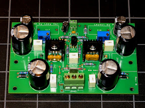
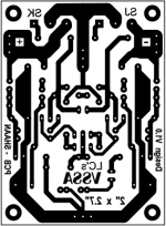
Here is the VSSA all through-hole PCB as promised. (update- we now have our first SMD PeeCeeBee! :nod: Check at the end of this post)

Dimensions: 2" x 2.7".

There is no compensation capacitors and zobel on-board. If found to be necessary then the Zobel may be connected off-board at the binding post solder joints, and the Cdom(s) under the board between B and C of the VAS trannies. These accessories may find their place in the next version of the board, can't say for sure 😉.

The resistors marked OFF1 and OFF2 are to be left for fine tuning of the offset. A value of between 100K and 1M at any of these will set the offset very close to zero. These should be connected after the board is fully assembled with all the other parts. Ideally any one of the two resistors will be needed. If connecting on the positive side seems to increase the offset then leave that and concentrate on the negative side only.

The amp can be run from +/-15V upto +/-35V. The only part that needs to be varied is the default 15K resistors which are for 35V operation. I Use 10K for my 16V setup. This value is best decided through direct measuring of the VAS current at the 10ohm degenerators at their emitters. 10mA is a good bias, with small "U" shaped heatsinks for the VAS. Increase to 20mA if you can keep them cold by using better heatsinks. The trannies are aligned so that a single metal piece can be used for both. Don't forget mica insulator if this is your choice.

Pix of my finished and assembled boards:

DSC00799.JPG


DSC00800.JPG


If you have any queries about the board and setup etc. then feel free to post it here. I'll help as much as I can.

Happy listening.
shaan

edit:- The layout is in the VSSAbottom.pdf file.


Important:- Visitors/posters are welcome to modify any of the layouts according to their need and/or add totally new designs. However, if you want to use CCS or Multilayer Layout or Parallel capacitors in the feedback network then please post your VSSA experiment and results in the original VSSA thread. Link >Here<. This thread's topic is single layer printed circuit board designs based on the VSSA schematic without the above mentioned accessories, shown in one of the pictures attached below. Thanks for your co-operation.


Update(19/11/2014):

More Tested PeeCeeBee designs(kind contribution by fellow diy-ers):

1. By PMI:- Click >Here< (Pro-style layout with under-board MOSFET mount).
Pete.jpg


2. By Jason:- Click >Here< (TO3 output MOSFETs)
Jason.JPG


3. By dobrivoje:- Click >Here< (large onboard input film capacitor)
Dob.jpg


4. By John:- Click >Here< (old-school hand-drawn layout with curves)
John.jpg


5. By Damanhuri:- Click >Here< (Spacious layout with a lot of on-board PS decoupling)
Daman.jpg


6. By Olafk:- Click >Here< (Lovely Looking SMD PeeCeeBee)
PeeCeeBee_SMD_03.jpg


Update(6/2/2013):

Some o'scope shots of PeeCeeBee performance:

1. By PMI:- Click >Here<

2. By nicos:- Click >Here<

3. By thimios:- Click >Here<

🙂

Attachments

The Boom Unit...

Introduction:
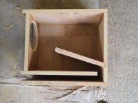
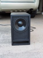
For years I've owned a Logitech X-503 multimedia system that provides the sound for my main PC. At the time I purchased it, it was around US$70, which was quite a good price, considering that the system consisted of 10" small 1.7" drivers (two in each of the satellites) and a 4" driver in a gnat-sized vented box to provide bass duties. The satellites aren't too bad (nothing that can't be fixed with a bit of EQ), but the bass unit was definitely a study in compromises. The driver has a relatively high Q and the box is tuned to around 80 Hz, so the end result is a big peak around that frequency that makes everything sound "robust", until you notice that a lot of the low notes are actually missing. Interestingly enough, the output from the bass unit's amplifier is not rolled off (significantly) below 80 Hz, which means that the driver does end up getting signal below Fb. The amplifier must incorporate some sort of dynamic EQ though, because even when turned up, there's no sounds of significant distress from the driver when it's fed very low frequencies.

Anyway, with no very low frequencies to speak off, the "bass unit' had to go, and I decided to replace it with a subwoofer design based around the Dayton DCS205 8" subwoofer driver. For this particular design, I wanted a solution that had an Fb around 32 Hz, as my intent was to use EQ to address the low-frequency performance in-room, and the lowest band on the simple EQ included with the PC was centered at 32 Hz.

So, I went to work on a new Excel workbook to describe the design, and I eventually came up with an MLTL-looking design that was around 26.6 litres net and 45 litres gross, primarily due to the use of 21mm MDF for the build. The corresponding Hornresp sim showed a response that gently slopes down from 100 Hz to just above 30 Hz, just right for what I wanted. The workbook is also able to export a data file in the required format for easy importing into Hornresp, which made the whole simulation process a lot easer. Note that in Hornresp I opted to include in the model the effect of puttling some polyester fiberfill in the first section of the alignment. According to the sim, this would drop the resonance frequency (Fb) a bit, and smooth the response in the passband. Real-world measurements of the built subwoofer confirm that the added filling achieved these goals. Note also that the predicted frequency response in Hornresp is slightly optimistic, as Hornresp does not account for the impact of box losses. The rolloff from 100 Hz to 40 Hz is slightly steeper than predicted, and the "corner" at around 32 Hz is a bit shallower.

Results
After building the box, the first thing I did was perform an impedance measurement, which suggested that Fb, which turned out to be around 33 Hz, was pretty close to that predicted by the Hornresp simularion I also performed some linearity tests, to see if subwoofer maintained its frequency response at higher input power levels (which would happen if port compression was low). Hornresp predicted that Xmax would start to be exceeded at 24.3V (the equivalent of just under 150W), and I tested at up to 25.4V (the equivalent of just over 160W). The subwoofer maintained its composure up to about -6dB, and then vent noise started to become audible. Still, it reached around -3dB from the peak input, or basically 80W, before the response at lower frequencies changed noticeably (according to the measured response), As this subwoofer is not going to see anything more than 25W in actual use (it's going to be powered by the Logitech X530's amplifier, after all), it looks like I'm never going to hear that vent noise - a good thing because this subwoofer is going to be located about three feet away from me, right behind my desk. Peak THD is also pretty low at 5.22% at about 20W input, most of which is 2nd order, so a lot less noticeable and objectionable. This suggests that the subwoofer is going to sound "clean" in actual use, and I can confirm that it does.

Conclusion
After messing around with tapped horns for awhile, it was nice to return to a relatively simple alignment, and this little subwoofer based around an 8" driver delivers all that I need for my multimedia system. If I was building this for another purpose, I might likely opt to flare the port's exit a bit, to reduce vent noise and compression effects at high volumes even further.

Attachments

  • 2017-08-27 (11).png
    2017-08-27 (11).png
    170.2 KB · Views: 1,109
  • 20170819-boom-unit.jpg
    20170819-boom-unit.jpg
    97.3 KB · Views: 1,093
  • 20170827-boomunit.jpg
    20170827-boomunit.jpg
    132.1 KB · Views: 1,092
  • 2017-08-21 (1).png
    2017-08-21 (1).png
    114.7 KB · Views: 1,049
  • 2017-08-27 (10).png
    2017-08-27 (10).png
    157.9 KB · Views: 1,046

Capital Audio Fest 2024 H1

CAPITAL Audio Fest 2022 Room 310

Nov 11-13

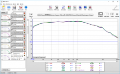
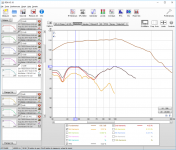
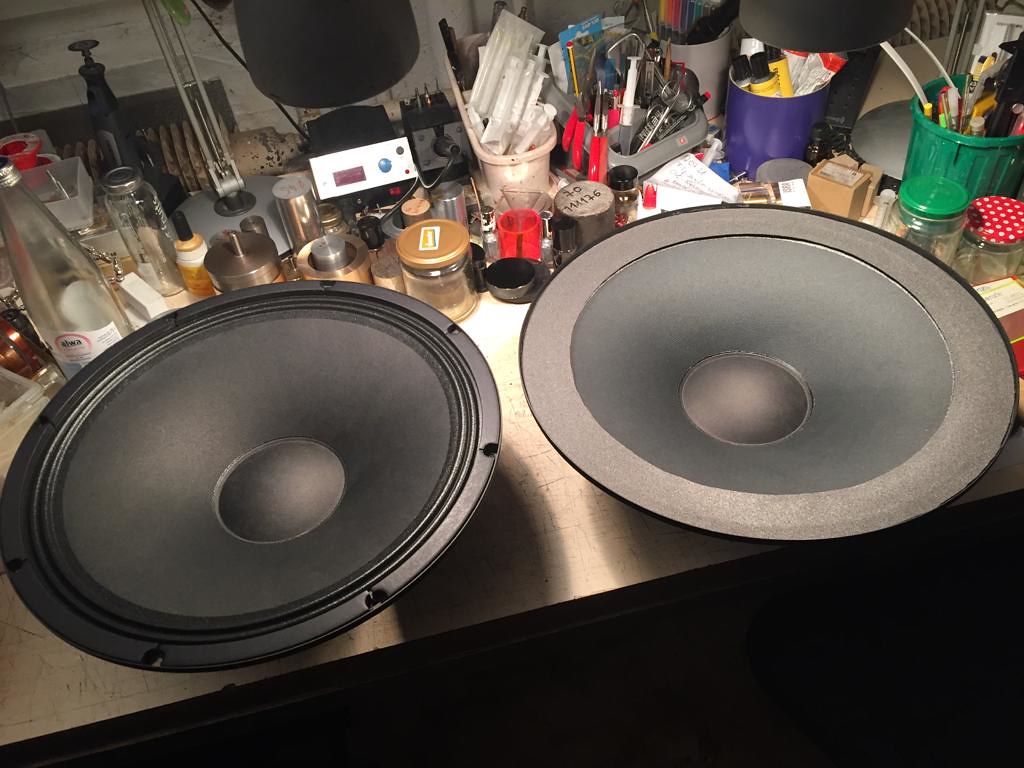
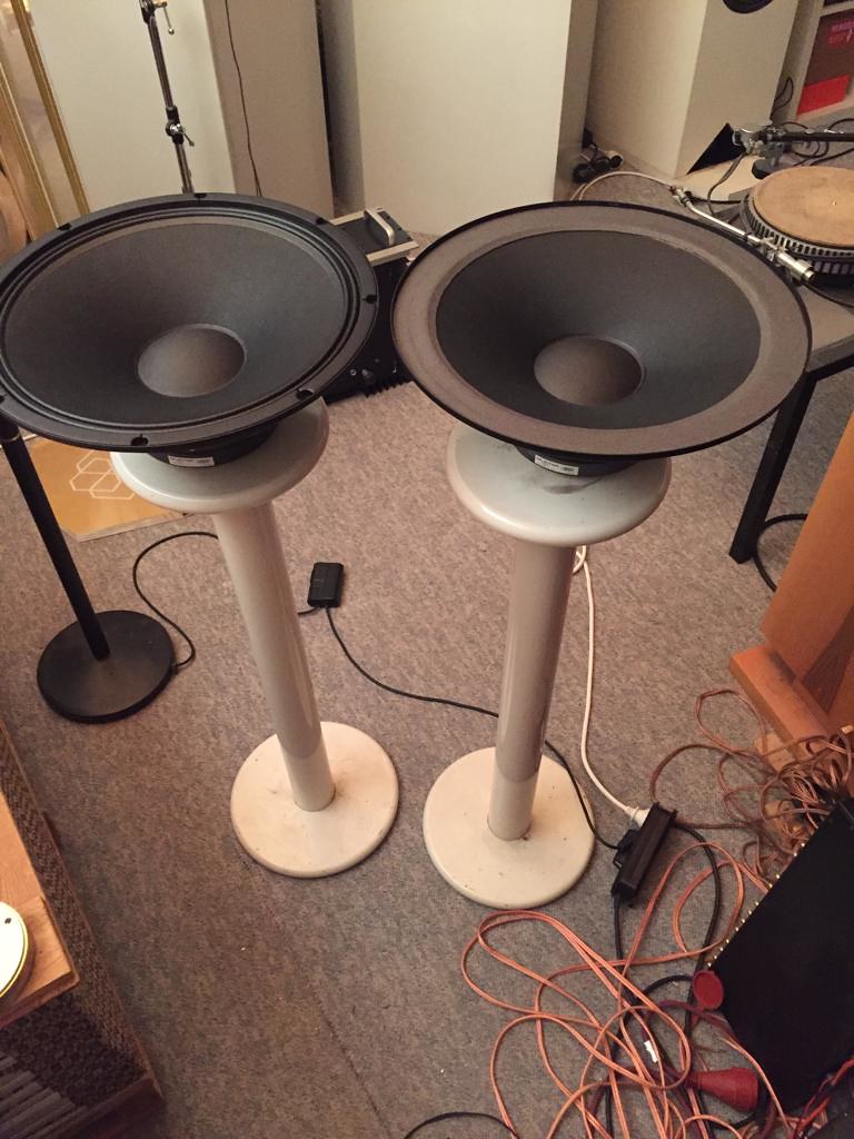
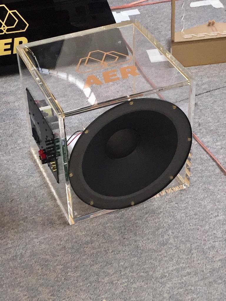
I wanted to introduce to you the new excellent and fine sounding base driver AER Studiobass 2 (15 inch) that I finished after many dozens of hours of work. I hope that you will be amazed as much as we are. Kind regards, Filip

On the pictures above on the left side is the old Inferior driver and on the right side the beautiful sounding new driver
It is the only Base driver to my knowledge on the world market that has a flat suspension.

52396157361_ecb6fb6d0f_b.jpg

52396589255_05c7afcba2_b.jpg

52396449889_c938e7dde9_b.jpg

LM317/337 Identification

Hi,

I bought some Surface mount LM317 and LM337 regulators sometime ago. Now I need to use them, and I cannot identify which is which. The markings are very much like data production code rather than device type numbers. can anyone tell me how to tell which is which?
FA19B4A0-2C3C-47C7-BA13-410CEA53010F.jpeg41885AF5-8A9A-4EC6-82E4-655C644D33DC.jpeg41885AF5-8A9A-4EC6-82E4-655C644D33DC.jpegFA19B4A0-2C3C-47C7-BA13-410CEA53010F.jpeg41885AF5-8A9A-4EC6-82E4-655C644D33DC.jpeg

Attachments

  • E60474EC-536C-4BFF-B6C8-CE1C2386C1B5.jpeg
    E60474EC-536C-4BFF-B6C8-CE1C2386C1B5.jpeg
    562.1 KB · Views: 106
  • 7B52A490-DB00-4583-A08B-539FACA91BC3.jpeg
    7B52A490-DB00-4583-A08B-539FACA91BC3.jpeg
    404.5 KB · Views: 112

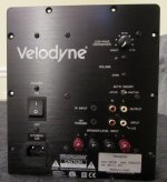
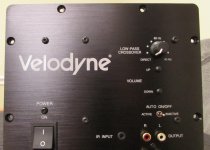
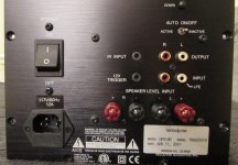
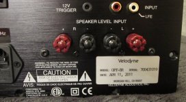
Velodyne Optimum 1200W Plate Amplifier (New)

Velodyne Optimum 1200W Plate Amplifier (NOS)

I have a mint (never used, never mounted) plate amplifier for the Velodyne Optmum subwoofer.

This is currently listed here: Velodyne Optimum 8 1200W Subwoofer Amplifier New 100 Working SN700431019 | eBay

I would accept selling it for $225 plus shipping and PayPal fees.

Attachments

  • IMG_1965.jpg
    IMG_1965.jpg
    601 KB · Views: 336
  • IMG_1968.jpg
    IMG_1968.jpg
    823.1 KB · Views: 315
  • IMG_1971.jpg
    IMG_1971.jpg
    769.9 KB · Views: 286
  • IMG_1973.jpg
    IMG_1973.jpg
    723 KB · Views: 303
  • IMG_1975.jpg
    IMG_1975.jpg
    739.9 KB · Views: 212
  • IMG_1943.JPG
    IMG_1943.JPG
    847.3 KB · Views: 326
  • IMG_1950.jpg
    IMG_1950.jpg
    501 KB · Views: 180
  • IMG_1959.jpg
    IMG_1959.jpg
    619.5 KB · Views: 180
  • IMG_1960.jpg
    IMG_1960.jpg
    791.3 KB · Views: 177

Nikko Alpha ii Trying to decide which caps to use for power filter.

Hello, I have a set of two different brands of capacitors to install in my Nikko alpha ii power amp and can't decide which are better to use.
When the amp was new, it came with 10,000uf 63V 85 degree ones that had been changed out to others before I got the amp.
The ones that were in it when I got it were Jamicon 10,000uf 100V 85 degree units.
I am doing a total re-cap of the entire amp and figured I would replace the filter caps as well while I have it all apart.
I purchased a kit with all caps for the amp, and have no issues with any of them except the filter caps..... and reading all of the forums has got me a bit confused.
Have new caps from Mouser here or new caps that came with the kit.
The choices are: EKMH630VSN103MA50S Nippon United Chemi-Con 10,000uf 63v 105 degrees or Kemet ALC70A103EH100 10,000uf 100v 85 degrees.
I have read some bad things about the Kemets used as power supply filter caps, but not sure if it pertains to these particular ones. Specs are not too bad on either....
So hoping I can get some suggestions from those who know more about this than I do.
Note: I posted this also in the Parts Thread.
Thanks!!!
Russ

Advice wanted on fullrange driver for BLH

I would like to get advice on choice of a 6" - 7" fullrange driver for a backloaded horn.
Man years ago I built a BLH based on Ron Clarke's Austin126 design. It uses a Fostex FE108ez and I am very pleased with the result. Now I wish to build another BLH for a larger room and with a larger driver. It will be fed by a push-pull 300B 20W amplifier. I am thinking of basing the cabinet design on the Austin166 but I wonder what driver to use. The exact dimensions will of course depend on the driver parameters.
The music will primarily be classical orchestra and opera. Voice and midrange clarity is important but deep deep bass is not. Age and tinnitus means that response above 10 kHz is not so important. The listening room is 20 sq.m and the listening position is more or less on-axis.
An "obvious" choice would be the FE168ez but I know that there are newer drivers on the market (MarkAudio etc). Any suggestions? My budget limit is around the cost of the FE168ez (€300 - 400)

Thanks / Michael

Need Help identifying a potentiometer

I was gifted a pair of Def Tech BP2002 recently that needed some minor repair and I’ve got one fixed but kinda stuck on the second and hoping for help.

The amp turns on but that’s all I can tell because the two potentiometer for the amps need to be replaced as the posts are sheared off entirely (and I think set to their lowest volume). They are both marked as A5K but that’s all I can tell. Any help appreciated.

Pictures below:

Attachments

  • 47FD4753-1CEF-48CA-9D5F-673A553C0AE4.jpeg
    47FD4753-1CEF-48CA-9D5F-673A553C0AE4.jpeg
    364 KB · Views: 119
  • A65398F9-BE51-45AD-959D-F7AAFB68E874.jpeg
    A65398F9-BE51-45AD-959D-F7AAFB68E874.jpeg
    512 KB · Views: 109
  • CC6DC499-D733-44E6-A8F7-5073E9AAC1DE.jpeg
    CC6DC499-D733-44E6-A8F7-5073E9AAC1DE.jpeg
    448.3 KB · Views: 106
  • 085C813D-09EE-4E0A-87AE-8C559EB44E9C.jpeg
    085C813D-09EE-4E0A-87AE-8C559EB44E9C.jpeg
    484.1 KB · Views: 123
  • 1327FDA6-61AF-4350-9D51-8900A761F033.jpeg
    1327FDA6-61AF-4350-9D51-8900A761F033.jpeg
    506.5 KB · Views: 123
  • 4DFCD783-EB79-46A4-9713-C6A2653AFE23.jpeg
    4DFCD783-EB79-46A4-9713-C6A2653AFE23.jpeg
    515.7 KB · Views: 109
  • 8F7A2841-ABE5-40F5-A6E2-B241530866B0.jpeg
    8F7A2841-ABE5-40F5-A6E2-B241530866B0.jpeg
    551.7 KB · Views: 107
  • 3534B5FE-EF2A-4EBE-9174-6AC956014312.jpeg
    3534B5FE-EF2A-4EBE-9174-6AC956014312.jpeg
    500.9 KB · Views: 111

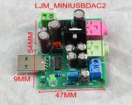
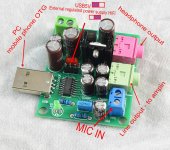
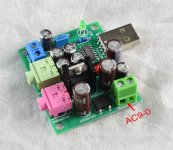
LJM- MINI USBDAC

This is a mini usbdac.
It has no exaggerated data. Only 16 bits 44-48k.
But his voice is good. You can plug in USB and use it directly. Or jump to an external power supply.
I recommend ac9-0. Use ONSEMI 7805 voltage stabilizing IC. Add three 1000uf low ESR capacitors.
in my opinion. The DAC should preferably use an external power supply. It can avoid the sound of hard disk in the computer. Or the noise of your appliances.
There is no need to pursue high data. CD discs also have only 16 bit 44K. But no one will think that the sound quality of CD is not good enough. I also make many 24 bit 32-bit 192-384k DACs. But I don't think it will be better.
The biggest benefit of using usbdac. Not a performance indicator. Instead, it can use ac9-0 power supply.
Plus voltage stabilizing IC. It can solve the interference of computer or mobile phone.
I found a Meizu 16xs mobile phone. Connect it.
It has a good sound without any settings.

Attachments

  • MINIUSBDAC1.JPG
    MINIUSBDAC1.JPG
    508.8 KB · Views: 514
  • MINIUSBDAC2.JPG
    MINIUSBDAC2.JPG
    679 KB · Views: 498
  • MINIUSBDAC3.JPG
    MINIUSBDAC3.JPG
    474.5 KB · Views: 448
  • MINIUSBDAC4.JPG
    MINIUSBDAC4.JPG
    364.4 KB · Views: 426
  • MINIUSBDAC5.JPG
    MINIUSBDAC5.JPG
    383.8 KB · Views: 433
  • MINIUSBDAC7.JPG
    MINIUSBDAC7.JPG
    390.6 KB · Views: 293
  • MINIUSBDAC8.jpg
    MINIUSBDAC8.jpg
    833.6 KB · Views: 363

Adcom GFA-555 buzz/noise (low level)

I've searched the site for something similar to my problem, but there isn't anything that fully complies to my situation. So here it goes:

Looking for ideas on where to start. The amp was refurbished by me. Original schematic, no mods. Changed all electrolytics and transistors on the input board. Replaced feedback wiring (original wiring was weak/corroded at the input board connection). As is known and common knowledge, this amp model has a bit of very low level buzz (I wouldn't call it hum, it is more a kind of 60hz plus lots of harmonics), and this buzz can be heard with your ear pegged to the mid woofer and/or tweeter. But it is inaudible a few inches away. Quite normal.

Next step in refurbishing this amp, was to add speaker protection. I installed a Chinese completely assembled rig, which includes a 120V to 12V mini toroidal transformer. So it was very easy to get this thing going inside the amp's chassis. Got the 120V from the power distribution strip inside the amp, which feeds the amp's transformer after the power switch. So the speaker protection board is powered up/down by the main power switch as well.

The rest of the Speaker Protection board is wired this way: Input ground, directly to star ground point. Input positives, wired straight to each channel's output stage positive.

Speaker posts are wired this way: grounds go directly from the speaker posts to the star ground point. I saw no point in wiring the speaker grounds through the speaker protection board, as this device is common ground and does not switch the ground, only the positives. speaker post positives (+) go to the speaker protection device's positive outputs.

Input board is wired this way: main ground wired directly to star ground point. feedback grounds, directly to star ground point. Feedback positives, directly to each channel's output stage positive.

The amp works OK, but now the "buzz" is appreciably higher than before. It can now be heard (albeit faintly) a few feet (4-5 ft away) on a quiet morning through 90db sensitivity speakers.

The star ground is bolted down this way, from top to bottom:

Input board ground
Feedback ground
Speaker protection board input ground
Speaker negative posts
Chassis Ground


Before doing anything, I'd like to read your ideas on how to reduce or, possibly, eliminate this buzz.

Cheers!
Luis

XINDAK MUSE DELUXE 1.0 power on but no work

Hello.
CD player XINDAK MUSE DELUXE 1.0.
Power on,but no display and any fonction.
Only on/off knob works on front panel.
All 5 fuses are ok.
All voltages of power transformer are ok.
With remote control power on/of working.
No service manual
Please need help.

Attachments

  • IMG_20220930_223835.jpg
    IMG_20220930_223835.jpg
    270.9 KB · Views: 189
  • IMG_20220930_222650.jpg
    IMG_20220930_222650.jpg
    492.3 KB · Views: 320

Where can I get a flange for this port hole?

Hi All,

I just finished building a pair of Audio Nirvana 10" Drivers in their 2.8 "Big Port" cabinet (the large pic below) and I am looking for something to line the port hole at the bottom, which is 6". When I look online (see little pic below) it seems pretty common, but for whatever reason i can't seem to find anything. I suspect it's maybe a matter of terminology and I am not searching for whatever this thing is called? I do find some port flanges, but not for 6" cutout. I was looking for something to line the port that I could attach some grill cloth to the back of, to keep curious hands out of the speaker.

Thanks for looking!


cus193-334.jpg


IMG_1793.jpg

Tube flavour for 5.1 dual-purpose system

Musical Fidelity, well regarded as Hi-fi, added new equipment back in the days (that technically would contaminate the signal) in an attempt to increase audio listening pleasure. This was a tube stage that connects before amplification, and I think most folks know about this. My type of questions always get called effects devices and ignored or told to be moved to instruments and PA

My system is getting assembled, according to the details further below from my thread in the class D area to discuss the amp boards and power supplies. I need some direction with the tubes, some peer reviews and suggestions would be very highly appreciated

I am about to start ordering some online kits and boards that are tube based. I think I need one setup to provide channel tubyness and I have the desire to have one or two aux channels that have a tube based preamp and tone on them that are switchable to take them out of the circuit

Tubyness
I have selected this device for channel tubyness, may be able to get away with 3 units to flavour my 5.1 channels independently. I won’t be using the .1 output of the decoder, instead the signal will be routed in the decoder to the main L and R speakers. I hope to use the unit flavouring FL and FR as the system headphone output too and the signal out from this lil amp with have a low passed signal for system subwoofer
  • Am I heading in the right direction with this board?
  • How does it work without output transformers?
  • Are there any output transformers that may enhance the task that I am asking of these?
  • Are input transformers with this of any merit?
  • Is it ok to run the headphone output into the input of the class d boards?
  • I would like to run a switching power supply instead of a "ring cow". Is this ok to do with this design? Should I take out the regulator stuff out of this board if I find a switching supply?

SIngle ended tube triode amplifier for hifi 6N5P 6N5C Headphone amplifier class A (will order 1 after posting this)

Aux channel preamp
This one looks interesting. I have 8 of these tubes on hand, and they are nice golden NOS Russians. I am going to order this board too and see if there is a way to increase gain and to mod to a tone unit too
  • Am I heading in the right direction with this board?
  • How does it work without output transformers?
  • Are there any output transformers that may enhance the task that I am asking of these?
  • Are input transformers with this of any merit?
  • Is it ok to run the output of this into the input of the tube headphone board?
  • I would like to run a switching power supply instead of a "ring cow". Is this ok to do with this design? Should I take out the regulator stuff out of this board if I find a switching supply?

6N3 Preamplifier Circuit Board

This one is also attractive, but I'll only have the tube that comes with the kit
- Is this a better option?

TR2 6DJ8 ECC88 E88CC 6922 Tube Buffer Pre-amplifier


The following is from another thread in the class D area and provides the background into what I am doing. Eventually, the hope is that I would have played with lots of gear and upgrades

I am actively putting together two systems:
System 1 - 5.1 for our home which serves as home cinema and home studio and used for studio tasks usually about once a week. This is an open plan type home that contains the kitchen and adults bedding in one room. Another same sized room is attached, with an amenities' room separating the two. A full length room run alongside the two main rooms and serves as my workshop, large double sliding doors from main room to workshop. These areas are contained in a square house structure

System 2 - 2.1 mobile box with 3 aux amplifier channels outputs, for a portable setup, which can supply extra amplification on demand with extra speakers. This will be installed in the workshop in a manner that allows easy removal. Mainly for listening to music while I am working, as well as for testing stuff without having to rip into the home system (I hope the logic for common device models is now apparent)

Request
The living room is not a place for a PA system, neither is the sound quality and ability of most of this sized PA systems out there for portable use acceptable. System 1 will be in operation here virtually 24/7. Think of these as being in the same category as the high-end Japanese audiophile disc players that feature mic inputs. I do not believe that anyone would be upset about such a disc player being discussed in a Hi-fi forum, so please may I request that discussion on an amplifier with the same feature doesn't upset anyone's sensibilities
Please regard these as a Hi-fi want to be setup. Both will be used for audio and video reproduction and appreciation and when liquid courage hits the spot, these systems should invite one to grab something and let loose

Desired feature:
  • An ability to keep electronic hardware and speaker driver models common to both systems
  • Emphasis is on quality quite nighttime sound reproduction and ample headroom without loosing composure for other times
  • Switch power supplies (desire to stay away from "ring cows")
  • Tubey audio signature (prefer the sound of the 300b amp for audio)
  • Engineered with the ability to input a live performer or two on demand (In other words, beautiful reproduction of prerecorded material, containing the "studio to mastering" process internally for a seamless jamalong)
  • Low pass channels to be either about; 400 clean watts into 8 ohms - 400 clean watts into 2 ohms - 2 x 200 clean watts into 4 ohms each
  • High pass channels to be about 100 watts clean into 4 ohms

This thread is for the tube devices that will be contained within

I have been saving for this project for a while, and in the meantime pouring over catalogues and specs and pestering folks with uneducated questions and ideas. Time to get to work on these, so I have ordered these items:

Signal IO
This unit will get fitted inside the amplifier case and provide most of the signal IO and act as the brains and system overall volume (has remote) as well as individual channel adjustment
4K@60Hz HDMI 2.0 Audio Extractor Converter DTS AC3 5.1CH Digital Audio Decoder ARC SPDIF Coaxial PC-USB Bluetooth Audio Input

Amplification
To be trailed as the low frequency amp
AIYIMA 500Wx2 Digital Power Amplifier (PSU on the board) x 1

To be trailed as the main channels amp and low frequency amp
HIFI Power IRS2092 500W Mono channel Digital power amplifier x 5
+ Lusya Dual DC 36V Output LLC Soft Switch 500W Switching Power Supply x 1

To be trailed as the main channels amp and bench amp
TDA7492 Amp Class D High-Power Digital Amplifier Board 2x50W (to run in bridge mode as a mono amp) x 1
+ 24V switching power supply board 4A 100W x 1

Speaker drivers
Low frequency
Dayton Audio RSS265HO-44 10" Reference Series HO DVC (delivered) x 1

Main channels
Already have a number of various pairs of bookshelf types on hand. Working on an interesting 6" coaxial speaker alongside this project, I am using some very interesting sounding drivers that I auditioned and bought, but I fear derision on my choice here

Reason to post thread
I am getting some promising looking kit that might help me acquired the desired sound system. Please guys, help me with peer review of my choices and suggestions to gear that I may not have noticed. I know create folks out there will have some great ideas too. Please help with mod suggestions as well as education pointers in anything I may be lacking. This will also be a log for me to help keep track of my project

Thanks and regards
Randy
P.A Clipping

Hello all, I'm new to this so hopefully i can get some help and guidance.

Basically i have a powered behringer PMP4000 going to EV ZLX 12P active speakers. I'm taking the connections from the non powered side of the desk to the speakers, nothing from the speakon connections.

4 peice band. Bass, both guitars and vocals going into the desk. Our singer has a vocal processor also. I connected all in and turned all down, with the gain i started to put up to i seen it was just fine or in the yellow. Did this with all then then with faders star put volume to FOH. However when we get going its up to red all night. Do i need to change the desk? Any help would be appriciated.

Fan bush/sleeve

Long shot BUT I know there is a lot of intelligence roaming around here so I thought I'd ask the question.
I have a desktop fan and the grease/oil keeps either drying up or going gooey causing the fan to spin slow. It is a bush type and I've tried singer oil, molybdenum grease, light machine oil, lithium grease, high temperature bearing grease, even marine bearing grease and it only lasts like a week of use.... dam annoying. The one at work does the same thing.
I could try replacing the bush with a ball bearing type but that's a lot of effort as it's probably an odd size.
If anyone knows anything else I could use let me know!!!
Cheers

FS: AudioTechnology 18H52 06 13 SDKA

Pair of used AudioTechnology 18H52-06-13-SDKA-LR

Located in Australia, will ship US/worldwide.

Selling the pair for 300 US + Shipping + PP fees.


T/S Data
Fs 32 Hz
Vas 50 Liter
Qms 4,92
Qes 0,27
Qts 0,25
Re 5,4 Ω
Nominal Impedance 8 Ω
BxL 7,4 N/A
Cms 1,28 mm/N
SD 137 cm²
Mmd 12,3 g
Mms 13,2 g
Rms 0,54 Kg/s
Power handling 120 W
Acceleration factor 559
Efficiency SPL 90 dB
Sensitivity USPL 92 dB
Efficiency Bandwidth Product 121 Hz
X-Max 4 mm
Max Excursion 32 mm
Inductance @ 1,6KHz 0,09 mH

Attachments

  • 20220925_182536.jpg
    20220925_182536.jpg
    718.8 KB · Views: 168
  • 20220925_182553.jpg
    20220925_182553.jpg
    442 KB · Views: 144
  • 20220925_182607.jpg
    20220925_182607.jpg
    824.9 KB · Views: 149

Smoothing capacitors. Can someone help educate me?

Complete amateur with some experience but plenty of enthusiasm.... The last device I worked on was a 1970s solid state hifi amplifier with two 10,000uF capacitors smoothing each channel. On the bench right now, is an early '50s table-top radio which has two 16uF smoothing the mains.

Technology and purpose are different, I know, but the difference seems enormous.
  • Sugden A48: solid state, 45W, 'hifi' (high bandwidth, low noise, etc.)
  • HMV 1121: valve, <5W, 'lofi' (adequate for AM radio)
What are the issues at stake?

Thanks

Perhaps more information than anyone wants to know about the early years of Mobile Fidelity Sound Lab....

MFSL has been in the news. I first became aware of MFSL in the late 1970s; by 1986 I had placed a project with them.

Herb Belkin was a larger-than life figure. So, here's a link to my memoir of him.

https://positive-feedback.com/audio-discourse/mfsl-herb-belkin/

The photo is of Herb (second from the left) circa 1974 with the then line-up of the band Genesis. Herb discovered and signed The Raspberries and Grand Funk Railroad, among others, while working for a succession of major labels before stumbling into MFSL via his connections to Pink Floyd. Rest in Peace, Herb.

Attachments

  • Genesis Herb Belkin.jpg
    Genesis Herb Belkin.jpg
    44.4 KB · Views: 103
  • Like
Reactions: vinylkid58

Help understanding this preamp desing, by R Slone.

Hello,

Before I build a circuit I like to understand how and why it's constructed as is it. Lately I've read "The audiophile's project sourcebook" by Randy Slone, and one of his preamp designs catch my attention. It's really nothing more than a non-inverting opamp (voltage gain about 13,5), see the attached schematic. But what bothers me is why I can's tell the reasons for all the components.
Screenshot from 2022-09-29 21-32-05.png

- Capacitor C3 in the feedback loop is there for limit the bandwidth of the amp, I assume? But to which frequency (value of C3 is 36pF)?

- The purpose of capacitor C2 should be to make DC gain zero, since it will act as an open circuit for DC. Therefore no need for input capacitor?

- C1 and R2 and can't tell why he put them there.

- R5 is there to isolate the opamp from eventually capacitive loads (?).

Appreciate some answer, unfortonetly the book doesn't explain this, for some, obvious things.

Crown Micro-tech 2400 bias problem (odep?)

Not very experienced here and running in circles so hoping for an helicopter view from more experienced users or an hindsight from experiences..

I am able basically to set only three out of four biases in their sweet spots (300-320mV).

The NPN left channel high-side bias is the problematic one (measured at R302 and set by R326 trimpot) as turning the pot makes no sensible change; the bias at startup is rather low at 50mV (while all other biases rise very promptly to sweet spots) and sloooowly rises up to 200-250mV at maximum over some 10 minutes or so.
I checked the output board, NPN side, comparing the channels and while components all seem to be working (diodes are ok, transistors in circuit appears to be ok too - except bias voltages on 0,2ohn 3W emitter resistors which are rather different on the 6 output transistors), I thought everything was ok.. then read about the Odep system (the front led is always lit as if the amp is fully working) and thought it might be the one to draw current from the output transistors somehow..

I checked voltages on the odep board, and it had not been possible to properly set odep + of the channel in question. I happened to find a resistor which sensibly drifted out of spec (R134). Substituted it and then hoped.. but still the amp bias is not working and odep + is still not

I then decided to take out the six output transistors but they all seem (seem, meaning that my diode tester procedure might not be fool proof, but I would assume they are all ok) to be ok and put them back in.

Of course I'll try to post a schematic as soon as possible, but any hint how to go on with what possibly to check will be appreciated, thanks!

Lii Audio F6 OB

Decided to go a whole different direction with this project when I found out about the F6 drivers by Lii Audio. My logic was that with these I could make my modest system much simpler and since my crossover building skills are non-existent, these were the perfect solution. They're wired in series-parallel for an 8ohm load and with my diy sub everything sounds perfect for me!

Someone mentioned that I should have a lot of comb filtering with these having this many drivers all playing the same frequencies and I'm wondering what the thoughts are on this? I a/b'd them with my smaller 3-way baffles and can't tell much difference other than these have a larger sound to them. Don't hear any weirdness going on. What I could find basically indicates that it isn't much of an issue in a vertical array and is inaudible in many other instances. Just curious if this is an issue I should be concerned with.

Chris

Attachments

  • 20220918_163629_HDR~2.jpg
    20220918_163629_HDR~2.jpg
    399.8 KB · Views: 225

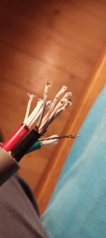
How tf do I remove the teflon insulation from this cable?

Hi

I bought this cable here https://www.audiophonics.fr/en/cabl...lded-power-cable-occ-553mm-o165mm-p-6456.html

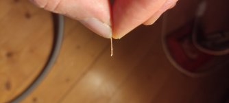
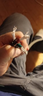
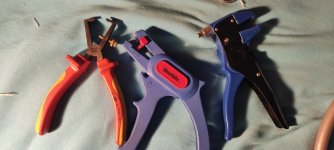
Now I need to remove the Teflon insulation surrounding each conductor, it's really thing as you can see on the pictures. I would really like to avoid damaging the copper stands, I already had to cut away 3cm of cable because the only way I managed to remove the Teflon was with a knife and peeling it a way like potatoes. I tried 3 different cable removal tools (see picture= and couldn't get any to work, maybe they are not suitable for this situation I am not sure.

It's really elastic, almost like chewing gum and it's a very thin layer.

Suggestions are welcome, I have never done this before.

Best regards and ty vm

Attachments

  • IMG_20220907_233711.jpg
    IMG_20220907_233711.jpg
    113.4 KB · Views: 316
  • IMG_20220907_233744.jpg
    IMG_20220907_233744.jpg
    92.8 KB · Views: 276
  • IMG_20220907_234040.jpg
    IMG_20220907_234040.jpg
    162.8 KB · Views: 260
  • 1662587930525.jpg
    1662587930525.jpg
    353.7 KB · Views: 300

repair the epicenter audiocontrol Concert Series

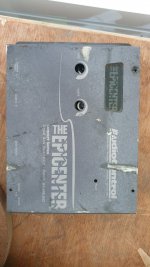
hello friends, I am looking to repair a the epicenter at the beginning it started to send a very high frequency or a strong and annoying bass now it does not regulate try to try another control and I had no luck I already checked potentiometers and operational amplifiers and I have not been able to make it work, thanks for your support.

Attachments

  • 20220930_142736.jpg
    20220930_142736.jpg
    356.8 KB · Views: 120

Found this 2 opamp sound quality boosters on aliexpress.

First is a opamp decoupling socket.

AVX Tantalum Capacitors
Murata MURATA C0G 5% Precision Capacitor
TDK X7R 10% Precision Capacitor
Murata MURATA X7R 10% Precision Capacitor
Koch Corona 3U Gold Plated Beryllium Copper Female Pin
Japan Hirosaki 63sn solder

EDIT: Forgot to add in that it advises against using it in a heavy negative feedback circuit.

1664558578970.png
1664558595508.png


Second is a Dual Single DIP8 to Single adapter.
It claims to increase the sound quality and drive force.
It puts the second chip as buffer, but idk if its that useful.


Imagine combining the 2 with a Dual to single adapter and using 4 opamps instead of a single dual one with the decoupling "socket".

EDIT: messed up the sizing.
  • Like
Reactions: Frabor

Luxman R-104 FM Logic

Someone gave me a Luxman R-104 receiver as partial payment for fixing some of his other equipment. He said it worked and it does; except the tuner does not remember any stations when the unit is turned off.

I looked for the usual culprit - a small battery by the logic chip. I saw what I thought was the battery but it is a capacitor. I think this is the precursor to the "supercapacitors" of today; it is rated "0.047 F / 5.5 volts." In other words, 47000 uF/5.5 volts.

I cannot access this part of the board without practically taking it out, so I put it aside. I guess I will solder test leads to the board and see what's up. But I was wondering if anyone else has any experience with this problem; I'm thinking it's pretty much a slam dunk to just replace this capacitor and restore the memory function.

So my question is, am I being too optimistic? Does anyone have any experience with this? Logic circuits in receivers is something I really don't know much about; I am capable of making only the basic checks. I'm all over everything else.

I can't find service literature for this unit. I know it's not one of the sought after Luxman units, but it is really nice - a pleasant surprise. It lacks nothing, except high output power.

So thanks for reading this.

Non stretchable T/T drive belt

We all know the flat T/T belts are nearly used universally for belt driven T/T's. Most know of their big disadvantage, they stretch which induces speed incontinences. The answer for many is to use Mylar tape belts which do not but these are a little fiddly to make up.
So what if we combined the two. have a rubber flat belt on the inside with a Mylar belt stuck (adhered) around the out side of the rubber belt. Surely that would give us the best of both worlds.

Cheers

Help me choose a 2" compression driver for my project (K-402 MEH) + a design question

So far I gathered a pair of K-402 horns, Crites 15" drivers, and most of the wood I'll need to build out a pair of multi-entry horns based on Chris A's work. The last major purchase I need to make is the compression drivers. I would love to use TAD-4002's but they have become unobtainable (with original Beryllium) from what I can find... That said, I think I've narrowed it down to 3 choices:

RADIAN 950BE PB
BMS 4592ND
Celestion AXi2050

Which would you guys recommend? Anything I'm missing one that should be on my short list? I need to cover roughly ~475hz - 20Khz...

If it matters, my center channel will be Bill's "1/2 of a 3D printed wave-guide" using a B&C 250 CD.. it will be active not passive however. Also I do not care that I would need an additional channel of amplification with the BMS option in order to avoid the reportedly crappy passive crossover that is available. Goal is end-game speakers so cost (within reason) can be ignored.

Second question is related to how to make all this look nice? I'm going to be cutting (giant) holes in my wall to mount all this in-wall. They will be located about 1/3rd of the way from the side walls (so NOT in corners). I know that I need to toe-in the speakers towards my MLP and in my mind I'm struggling to picture how to do this in a way that doesn't look like somebody just stuck a giant speaker in a hole-in-the-wall at an angle! If I were competent at 3D design I'd try to draw something up so they have a more built-in look but alas I am not (it's on my list). I will definitely be building grills for the horns. If you haven't guessed I have a wife ;-)
Anyone got any ideas of how to integrate the angled box into the wall is some sort of elegant way?

PS Audio Phonolink II Circa 1991

I recently picked up a PS Audio Phonolink Phono Preamp from the early 1990s. Currently, it's working great, dead silent. It really must not have been used much, the exterior is a 8/10 and inside it looks like it just came out of the factory 10/10. Hoping someone might have a manual and even better a schematic. Given its age, it's time to recap. If anyone has any info about this unit, it would be greatly appreciated.

IMG_8708.jpegIMG_8710.jpeg

Boombox ORRBIS (active, 3-way, BT, WiFi)

Hi guys,
How do you find my new build?
Inspired by B&O Beosound Edge.

Movitone Orrbis:
Arylic Up2stream pro v3
Arylic DAC board
miniDSP 2x4
Amplifier:
ICEpower 700AS1 + 200AC + 200AC (350W + 100W + 100W @ 8 Ohms)
Speaker drivers:
SW26DBAC76-8 (10” subwoofer)
SB12NRX25-4 (4” midwoofer)
SB21SDCN-C000-4 (20mm tweeter)
Case:
MDF with 8mm powder coated aluminum face and back plate.
Laser engraved leather surround.
Dimnension: d500 x 112mm

Going to upgrade to Arylic Up2Stream HD DAC and miniDSP 2x4 HD

Remodeled Case to fit Satory 5" midwoofer and Bliesma T25 tweeter.

photo_2022-07-21_17-06-17.jpg
photo_2022-07-21_17-06-13.jpg
photo_2022-07-21_17-06-10.jpg
photo_2022-07-21_17-06-00.jpg
photo_2022-07-21_17-06-24.jpg
photo_2022-07-21_17-17-29.jpg
photo_2022-07-21_17-17-56.jpg

Removing NAD T753 Volume Control Knob

I am trying to recover use of the control buttons on the front panel of my NAD T753. Not sure what happened, but a good summary is "blunt force trama" probably from my kids playing pushed the Tone Defeat into the faceplate. I nolonger can use any controls on the front panel ... except for tone defeat. (go figure!)

I want to carefully dismantle enough of the unit to allow me to see what actually happened. But I am now stuck.

I need to remove the Volume Control Knob for the motorized control. The control body itself is welded to a circuit board. I *hope* that if I remove the knob on the front, I will see a nut or something around the shaft that I can then remove allowing me to remove the board from the back of the front face plate.

How do you get the knob on the outside of the unit off? It is firmly attached.

Thanks.

SPL limit for 2 way or 3way single point loudspeakers question

Guys,

this is a question that i had since many many years back, but it was until today that i dare to ask

so, why most of the mid grade ( QSC KW series , EV ETX, JBL SRX 800's ) V2 way or 3way PA cabinets
max SPL ratings are around 135 or 136 dB's

is because the limits of physics or because the limits of the drivers for that given price ( max 2k )
as far as i know the HF driver is padded because it have much better sensitivity that then LF driver
so the LF cant cope with the HF power limit and that is why manufacturers can only achieve around 135SPL's

i saw the new MEYER Panther series that are rated at around 150dB's SPL but those are linear cabinets and i think they cost above 8k each
but what about the 2 way single point PA loudspeakers
Projects by fanatics, for fanatics
Get answers and advice for everyone wanting to learn the art of audio.
Join the Community
507,689
Members
7,884,317
Messages

Filter

Forum Statistics

Threads
406,041
Messages
7,884,317
Members
507,689
Latest member
Giannikos