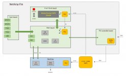
OPA627 VS Burson V5 VS Burson V6 Classic op-amps perceived quality of musical reproduction
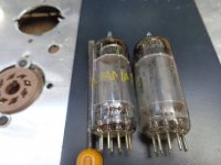
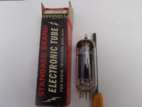
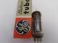
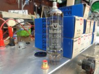
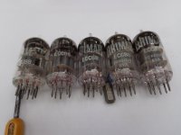
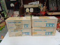
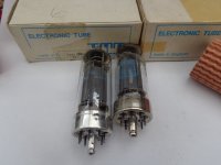
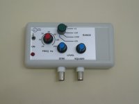
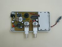
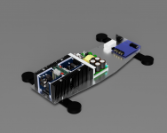
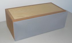
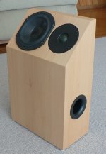
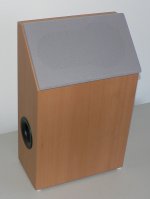
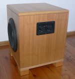
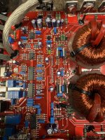
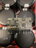
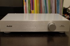
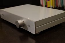
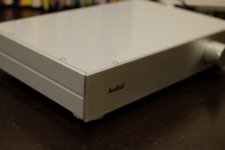
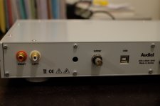
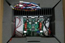
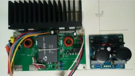
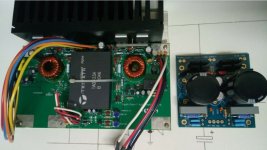
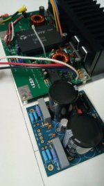
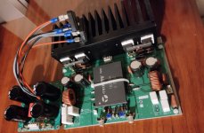
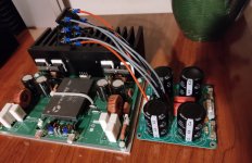
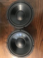
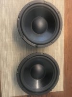
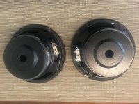
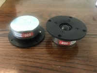
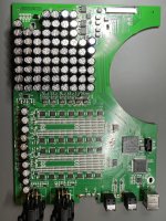
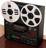
Images show OPA627, Burson V5 and Buson V6 Classic op-amps and their relative size and Cyenne Dac 3100 with OPA627 and two V6 Classic op-amps in sockets.
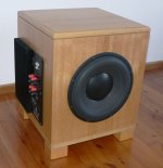
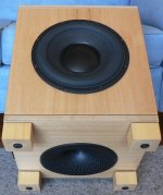
In exchange for two Burson Classic dual op-amps I writing my honest review of their performance in comparison to OPA627 and the Burson V5s I already own. My system is composed of an Asus Gaming Computer running JRiver media center 28 which I modified to up samples all files to 96 KHz which are stored on a Passport external hard drive. I have an external Musiland external soundcard I use with optical out through a glass optical interconnect to a Cyenne 3100 DAC with three replaceable op-amp sockets. The DAC output goes to a Cambridge Audio CXA60 amp. I have Mordaunt-Short Aviano 6 speakers and a Wharfedale subwoofer. The Mordaunt-Short speakers are very neutral and I can hear differences in op-amps in the DAC typically. Lm4562 DAC chips came with the Cyenne Dac originally, but I found that despite their low THD, they sounded clean, but lean in expression. I previously owned a Maverick D2 DAC with 3 OPA627 op-amps and found them more textured and open. So, I am reviewing the OPA627 as a baseline vs the two Burson op-amps to see any difference. My dedicated music room is highly acoustically treated and has a fairly straight equalization curve along the x axis, according to Room EQ Wizard, without any equalization required in the JRiver application to achieve this.

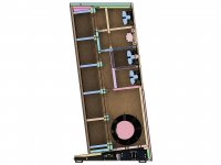
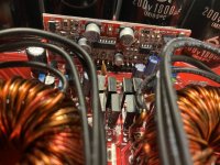
Above example of ceiling room treatment in dedicated music room.
I plan to look at the factors Buson uses to describe their op-amps: transparency, details, color and texture, and dynamics and soundstage when reviewing the op-amps previously noted.
Definitions:
Transparency: the sound is reproduced accurately without adding much extra.
Detail: hearing the small, fine sounds of a recording; the most delicate parts of the original sound.
Color and texture: Tone color or texture of a sound is the quality that allows you to separate two instruments playing the same instrument. It is hearing the different layers and harmonies of music.
Dynamics and soundstage: variation in loudness between notes in the spatial sound image presented to the listener.
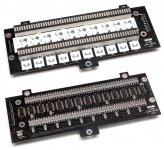
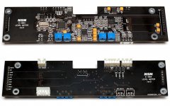
The Cyenne Dac has 3 removal socketed op-amps. One serves as the combiner op-amp for the DAC. The other 2 are gain op-amps. The gain sockets will vary from OPA627 to the Burson V5 to V6 Classic. I will listen to a playlist of Flac files with a minimum 44.1 KHz and make note of the above features of transparency, etc. for any sound characteristics noticeable for each op-amp.
The flowing listening set began with OPA627 in all three op-amp sockets followed by the Burson V5 in the gain op-amp sockets and OPA627 in the combiner op-amp socket.
Just Like A woman, live 1966 by Bob Dylan.
This is a beautiful 6:45 version of his studio song which only totals 4.42. With three OPA627 op-amps the song sounded less detailed than I remembered. I choose my music in this evaluation for its familiarity. Reference material I believe has to be used so elements like detail and transparency can be assessed as different from a typical presentation. Dylan’s guitar and voice had a sadly muted color and texture. It is actually a beautiful version of a song in which we hear Dylan during a grueling tour in 1966 play an emotionally different version of his studio album while leaning over his stool and expressing longingness and compassion during the song, not the derision found in his studio album. But the OPA627 did not convince me I was listening to a live performance of a wasted Dylan generously sharing his feelings of tenderness with the audience.
The Burson V5 turned the concert and song live. We hear the echo in the room and his harmonica notes are more present. The detail is enhanced. The whole texture and color of the song in his strained voice emoting his regret, not his signature emotional sneer. I was enveloped in the large soundstage during the recitation.
Visions of Johanna by Dylan, the studio track from Blonde on Blonde
The song sounded less textured as well with OPA627. Details were diminished. The notes were compressed and the soundstage was narrow. The music was colored, but with all the instruments the same color.
The Burson V5 again brought out more realism and detail. The bass is strong and Dylan sounds real, unfortunately the soundstage is medium but with clear textured sound separation with sharp details and accuracy.
Hotel California by The Eagles, MTV Live.
With the OPA627 texture is diminished in the guitar work and soundstage is small. Details seem muted. Henley seems to be singing through a cloth. There is a lack of presence.
The acoustic guitar beginning Hotel California with V5 sounds beautiful in its richness of color and texture. Its presence jumps out. The bass is stronger and more defined than with the OPA627 and the music seems more accurate. The instruments keep increasing as the music plays, but textural space is created for them. The vocal could be a bit more forward. But a great performance.
Maggot Brain by Funkadelic
In Maggot Brain with the OPA627 the echo in the left speaker of this beautiful guitar solo brings me right into the studio. The OPA627 shines when outputting the distorted gritty sounds displayed on this cut. I would like a little more transparency here but otherwise great performance.
With the Burson V5 the vocal is more authoritative at the beginning. The drum slap and echo is more detailed and colored. The solo is more in our face but cleaner than with the OPA627, although I like the OPA627 distortion guitar solo sound better. But the sound separation and soundstage are excellent with the Burson V5.
Early in The Morning by Harry Nilsson
Nilsson’s bouncy bluesy keyboard and infectious voice and lyric wants to be heard. But despite some spatial openness and slight texture separating the notes and voice, it was a boring presentation with OPA627.
The Burson V5 again has more detail and bass, but still the song lacks a natural and intimate soundstage. I want it to feel live, but it doesn’t.
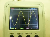
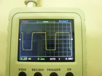
The Burson V5 performed better to my ears and with my equipment. It was less fatiguing than the OPA627. The frequency curves on the OPA627 and Burson V5 were identical with REW. The great details, texture, dynamics, presence, etc. with the Burson V5 made no change in frequency distribution. They were both flat.
Burson V6 Classic performance
The Burson V6 Classic has been reviewed frequently and most reviewers indicate it is a good fit for folk and jazz, but not necessarily for rock. I found this to be false in my evaluation. It is clear it is more evolved in design than the earlier produced V5 I already owned, particularly the better ventilation qualities on the V6. I chose the V6 Classic for review since the V6 vivid is based on the Burson V5 I already own and they seem to share many characteristics, if the published qualities in the bar graph are accurate. The V6 Classic seemed different enough from the V5 to interest me in hearing its advertised sonic qualities. Since the OPA627 was found lacking in previous listening tests, I filled the integrator op-amp socket of my Cyenne DAC with a Burson V5 and the gain op-amp sockets with the two V6 Classic op-amps I received from Burson.
Joni Mitchell The Asylum Albums CD 1 and CD 4
I could hear Joni’s deliberate pace in the music that reveals a more realistic music experience with a musical texture which was beautiful and a clarity that was a joy to listen to. Joni in her live performances on CD 4 sounded present in my listening room with a sweetness to her voice which was big and clear, yet textured with a beautiful timbre to her voice I had not previously heard; while the instruments encompassed me. The bass was strong amongst rounded vocals that echoed slightly, revealing the music hall acoustics. I had never heard such a beautiful voice, although I had heard Joni many times. Her phrasing was accomplished.
Roger Water, Amused to Death
The first five tracks on Roger Waters album, known for its soundstage and imagery, were listened to with the Burson V6 Classic op-amps. The spacing and imagery of the sound was revealing. The texture and dynamics of the music, with pounding drums, electric solo and the chorus singing was three dimensional. The best I have heard it. The presence of Rogers is real. I had oddly read that V6 Classic op-amps were not good for rock, as previously noted, but I had a different experience, the realism the Classics added to my system was nothing short of fantastic. The sound wrapped around the back of my head. Roger seemed to be singing in my face, he is so close.
Early in The Morning by Harry Nilsson
I was so disappointed in the OPA627 and Burson V5 presentation of Early in the Morning I wanted to give the V6 Classics a chance to properly present the song. With the Burson V6 Classics in the gain op-amp sockets, finally the song sounds real. The keys of the piano can be heard vibrating and Harry is singing next to me. There is a brilliant texture revealed by the Classic op-amps positioning the struck keys, voice and distant bass. The realism of musical timbre is heard with an energy in the sound not previously heard.
Kill City by Iggy Pop
Kill City with Iggy Pop followed, with Williamson on guitar. It is a textually dense and energetic album. Iggy is in your face while the listener is enveloped by this forceful performance. The songs are catchy and floor tapping. This is a vinyl quality performance in sound by the Burson V5 and Burson V6 Classic combination. There is an absence of distortion, only the authentic presentation of instruments and voice. A total musical presentation which envelopes you with its presence, but maintains its clarity and details. The tone of each note is cleanly offered, while grandly performed by Iggy in his musical prime.
Avenue B By Iggy Pop
Avenue B by Iggy is live and his spoken introduction echoed as he spoke in the theater. His guitar strings vibrate in front of me. His voice is huge. The texture and details of the sound is so real I believe I am in the theater. Details in his performance are brilliantly revealed in this live performance which I had not previously heard. It was obvious now the sounds were always present, but only revealed now with the V6 Classics by Burson in the Cyenne 3100 DAC.
Clearly many things affect my perception of the V5 combined with the V6. The V6 Classics are so much more realistic and texturally beautiful than the Burson V5. I am sure though they complement each other with their revealing musical presentation and clear sonic image and details previously never heard on my system. I would pay for the V6 Classic op-amps if they were not offered free for a review.
I do not know how Burson was able to design the V6 Classic to produce such a musically beautiful presentation, suitable for rock or folk in my view. I am convinced from my experience that op-amps can change the sound signature of a DAC for the better. The best op-amps I have found to my taste have been made by Burson. I realize an op-amp interacts with the DAC circuitry and another DAC might produce a difference in sound quality, but in my system, the sound was superb and these op-amps will remain in place.
The value of discrete op-amps is denigrated by many, however many such as PS Audio co-founder Paul McGowan mention the intolerance of heat of IC op-amps due to size limitations; while discrete op-amps are not limited in this respect. He further states that discrete op-amps can be designed with a certain sound in mind and the use of the highest performing circuits and endless designer choices. Of course, the success of the project depends on the ability of the designer.
Specifications can not alone explain an op-amps appeal. Claims that discrete op-amps have more distortion than IC op-amps is usually used by critics to support the claim discrete op-amps are not worth buying or using. Gaskell’s 2016 dissertation at McGill university mentions that many designers and critical listeners believe that low level distortion may impart a beneficial tonal, timbral, or transient quality. Small amounts of distortion in a signal affect the “warmth” of the sound. He lists several studies showing that distortion is preferred by many listeners and his dissertation’s conclusion is that low level capacitor and op-amp distortion was found pleasing to many listeners.
Metrics can only replace subjective testing if they correlate well with a jury response. Measurement equipment in audio has to correlate with what people find pleasing in music, not what measurements such as THD say is best. Gaslighting someone who says something sounds good when it has poorer specifications is not a way to improve the science of psychoacoustics in the development of measures which quantity what consumers find pleasing.
Finally, Harman’s “How to Listen” is a computer-based, self-guided software program which teaches listeners how to identify, classify and rate the quality of recorded and reproduced sounds according to their timbral, spatial, dynamic and nonlinear distortion attributes. Other critical listening programs are available and can be used to improve the evaluation and improvement of audio systems through trained listener evaluations of products. Many audio companies do this to improve speakers, DACs, Amps, etc. Improvement of listening skills may improve the opportunity for agreement between critics as to what sounds good. One study found audio salesmen had the best listening skills, better than music critics.
I would be happy to review any discrete op-amps that manufacturers wish to have honestly evaluated.


