Speaker Camp 2022 - Northern California

Speaker Camp
June 25, 2022

Sebastopol, California
About 1½ hours north of San Francisco, site of 2012’s Amp Camp

The build:
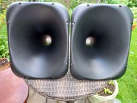
Moth Full Range in SLOB Open Baffle with Eminence 15” bass as featured in the Pass Lounge at BAF*
*(The BOFU sealed cabinet build previewed last Fall at BAF is sidelined for now.)

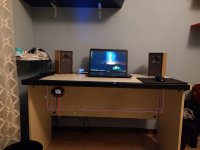
Completely built and finished open baffle in cherry wood with black base
ob front 3.JPG
‎‎
ob side 2.JPG
‎‎‎
ob rear.JPG

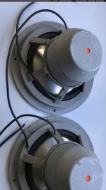
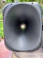
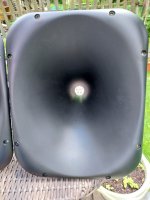
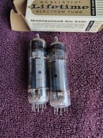
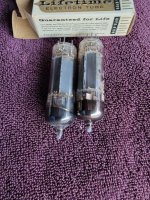
Note! - Full range driver will be a Moth, not the one shown in these photos

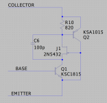
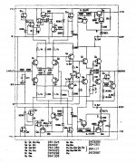
The build will include a bi-amped active crossover (thank you NP!) which means you will need 4 amplifier channels to drive the speakers.
An Amp Camp Amp or similar would drive the full rangers quite nicely

This is an easy build that can be done by a beginner. All woodworking and the finish are complete. Unfortunately, this build is likely too expensive for many younger beginners. We strongly encourage that campers bring novice family members and friends
to participate/observe in the process. Previous Amp and Speaker Camps had several attendees that
were in elementary, middle, and high school and everyone benefitted from their participation.

Plenty of space for car or tent camping the nights of June 24 and 25.

Price is $750/pr.
This is at cost or below, resulting from a great deal of support from Nelson Pass, who is planning to be in attendance at the camp.
This speaker and XO is his design, NOS full range drivers and cabinets.

28 spots available
Please indicate your interest by filling out this google form.


Details (please read!):
In the spirit of keeping things equally unfair to all, there will be a lottery to choose participants, drawing will take place April 10th.
If chosen, you will need to pay $750 by April 15, 2022 to keep your spot.
Spots that are unpaid after April 15 will be filled with other lottery participants, moving down the list so if you don’t initially get a spot, there is still hope.
Please only enter if you can attend in person. If you can’t make it to the camp for whatever reason, you will still be able to come collect the entire kit and take it home to build.
Sorry, no refunds.
Sorry, no shipping of kits. They must be taken away from the camp site after the build or picked up if for some reason you miss the build.
Car and tent camping at the site is fine the night before and the night following the camp. There is one bathroom out in the barn available for freshening up, otherwise try to be as boondocking-capable as you can.
Bring family and friends to observe or participate as appropriate. Any children in attendance will need supervision away from the build area.
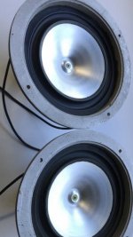
The Moth full range driver is in a relatively small open baffle.
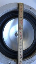
The downward facing Eminence bass driver is slot-loaded.
For best listening the speakers should be placed so the baffle is at least three feet away from the wall (so 18" from the rear of the bass driver to the wall).
  • Like
Reactions: AddiDub and dBel84

Nichicon VZ Series, what do you think?

http://nichicon-us.com/english/products/pdf/e-vz.pdf
I couldn't find the ESR for this series, they say it has high ripple.

I chose this series because its the only one that covers my whole amp
without taking caps from a different series or brand.

It's for my amp (all caps except signal path and ceramics).

I wanted the Elna Silmic II series but it doesn't have a 330uf 63v
and 0.22uf 10v caps and i don't want to have my whole amp with
one series except for two caps from another brand.

What do you recommend? does it really matter if it's not in the signal path?
Does the Nichicon VZ series has low ESR?

Popping in the Old Harman Kardon 930

This issue is not with the notorious startup and shut down pop on this receiver, but rather a popping sound on start up. It lasts for about 2 minutes and then goes away I presume a warm up. It happens in both speakers even with the volume at 0. I am thinking power supply. I did the old freeze spray trick on the TR903/2SC932 bipolar transistor. I am fairly sure that this is the culprit. After a spray it stopped the popping. It maybe on it's way out. Any suggestions for a replacement" I have found this a BD241A/C and need confirmation as to it's compatibility from the more knowledgeable. http://www.mouser.com/ds/2/389/CD00000938-14108.pdf

FYI most of the lytics have been replaced on the pre driver, power supply and preamp boards.

Schematic attached.

Attachments

A $$$ Turntable with a Richlite Plinth and a "Steampunk" Design Vibe

Fern & Roby is a small company that makes idiosyncratic loudspeakers, and also two turntables. The pictured one asks $8,500; the one with a 30-pound solid brass platter asks $10,500. Both have Richlite plinths. The stuff (Richlite) is dead as all get-out, and at that price tier, one assumes that Fern & Roby could have chosen almost any material.

https://www.fernandroby.com/products/details/the-montrose-heirloom-turntable-1

I continue trying to work the angles to get a pair of demo loudspeakers built, one in MDF, the other one identical except for the cabinet being made out of Richlite; and I will post any developments as they occur.

amb,

john

Attachments

  • montrose_angled_front.jpg
    montrose_angled_front.jpg
    22.2 KB · Views: 143

Harman Kardon HK 930 popping noise troubleshooting

The 930 is known for a loud pop after turn on, however, the particular unit on my bench keeps on popping for a few minutes after.

I first pulled the Main-In/Pre-Out jumpers and fed a signal directly into the amp. Other than the typical HK initial pop, there were no further eruptions. So the amp section would seem to be ok.

With the function switch set to Aux 1, I measured the voltage at the output (R) of the Tone Control PCB while also measuring it at the speaker output (R). I chose Aux 1 because this bypasses the Preamp board, making the Tone Control board the only board between the RCA input and the Preamp Out. Here's what I measured:

Initial Turn On

Tone Control: quickly fluctuating voltage as high as 1.4V DC.
Speaker: quickly fluctuating voltage as high as 19V DC.

First Three Minutes
Tone Control: voltage settling down to between 600mV and 700mV
Speaker: voltage still going as high as 2 - 3V, but beginning to drop to 150mV in tandem with the output of the Tone Control board.

After 10 Minutes
Tone Control: voltage fairly steady at 465mV
Speaker: voltage staying at around 115mV (still high for DC offset, so I'll likely replace the differential pairs to see if I can lower it)

Power Down
Speaker: spike of 16V or so, gradually dissipating.

I'm thinking there's either a leaky cap or a bad transistor on the Tone Control board. Maybe more likely a transistor since the issue seems to disappear after warm up. Unfortunately, the service manual doesn't include any reference voltages to measure against, which is how I would usually track down the offending component. While I can hit each transistor with a quick shot of freeze spray, I'd like to hear how others would suggest narrowing down the possibilities.

Another TA0104 Thread

Hello all,

This is a tripath TA0104A driver module from a Zapco car audio amplifier that is going into protect. I've got a thread going on this amp in the car audio forum, but have not had any response on what is hiding under the black blobs, so I thought I would try here.

Can someone tell me what the ICs/components are under the epoxy? If I could find a data sheet I might be able to surmise what they are doing.

What is the component labeled PLANE in between the two epoxy blobs on bottom of the picture?

Does anybody know of any method to test the TA0104A to tell if it is bad? After reading the other posts about these modules I realize they have long been extinct so If I could determine if it was bad that would give me an idea if I should be spending any more time on this amp.

Another thing, this amplifier has an ATmega103 M.C. which is also unavailable so I need to determine if it is good or not , if anyone has any advice on testing that.

Attachments

  • TA0104A Tripath.jpg
    TA0104A Tripath.jpg
    330 KB · Views: 109

Any tech in the Hudson valley,New York,to help with a few projects and problems

Hi I am near,new paltz,Woodstock,Kingston,rhienbeck,etc
I am doing a big move and very busy with the business and helping my wife's business so limited time to diagnose
Fix a aca camp amp ,one does not work (brought used from this site)
Fix a kenwood ka 3500 ,one channel oscillating
Few other projects also depending on your time and $
Thanks in advance
  • Like
Reactions: HeadShake

Isolation transformer

Here is one question about isolation transformers in use for audio systems.
Here comes to the shop one machine which is one isolation transformer but its configured in a way that i am not familiar with

Transformer is torodial
The primary has a tap for 230 -240 use ...fine with that
Secondary though is made from two windings of 115 V center taped .
so secondary will provide side to side 220-230V depending in the input
The center tap though goes to ground connected also in the enclosure and to the mains ground

I am not familiar with this practice can any one comment on pros and cons ?
kindest regards
Sakis

A wacky, chip-amp based solar project

I have already proposed a number of unhinged chip-amp projects:

https://www.diyaudio.com/community/threads/automatic-resonance-frequency-finder.254384/post-3886008
http://www.diyaudio.com/forums/chip-amps/176052-now-regulator-chip-jlh-amp.html
http://www.diyaudio.com/forums/chip-amps/192934-se-class-regulator-chip-amp-madness.html
http://www.diyaudio.com/forums/chip...oss-tringlotron-regulator-chip-amplifier.html
http://www.diyaudio.com/forums/chip-amps/193214-class-chip-amp-now-complementary-version.html
http://www.diyaudio.com/forums/chip...ator-chip-amp-family-welcomes-new-member.html
http://www.diyaudio.com/forums/chip-amps/175457-just-fun-regulator-chip-amplifier.html
https://www.diyaudio.com/community/threads/yet-another-funny-chip-amp.280777/post-4476559

Here is another one to add to the family: it is a solar "helper". It has the ability to inject a modest amount of power into the mains, from an array of photovoltaic cells.
It is not a solar inverter: it has no oscillator or timebase, no synchronization circuit, and it is incapable of operating as a stand-alone power source.

But how can it work then?
That's where the chip-amp steps into play: it is configured as a power negative resistance, connected to the mains via a transformer, to adapt the voltage, and for obvious safety reasons:

1666602279862.png


The circuit is based on a TDA1512, just because I had one patiently waiting in a drawer: any other chip-amp or power opamp would be suitable (and probably preferable, because the TDA1512 has annoying quirks).

The load (the transformer's primary) is connected between the output and the - input, and the current is sensed by a low-value resistor (R8, R9). On the + side, a resistive divider (R3, R5) injects a positive feedback signal matching the voltage on the sensing shunt, to generate the negative resistance.

The negative resistance engine itself is minimally simple, but there are lots of auxiliary circuits around: they are needed for a smooth, effective operation. The project is small-scale, but fully fledged and is much more than a mere proof of concept: it has to handle all the possible situations, and behave gracefully and safely all of the time. This requires optocouplers, relay, etc.
It is a lot of circuitry for a meagre 10W (peak!) output, and a continuous operation for more than 10 or 20 years would be required to amortize the building costs (unfortunately this might be reduced to two or three years with the rocketing energy prices), but it is fun, and it could be upscaled relatively easily.

In the subsequent posts, I shall describe in detail each section of the circuit, but in the meantime here are a few pics of the build:

1666622732312.jpeg


1666622832514.png


And this is the indoor unit:

1666622936965.jpeg


To be continued.....

Subwoofer enclosure integrated into the desk?

Hello everyone! I recently made a pair of small nearfield speakers using a modified Ciare PA065 fullrange driver. I love how they sound, but they can hit about 70/80Hz in my room, under that there isn't anything and the cone moves a lot. With certain songs it's completely fine but some others make me wish I had a subwoofer. I have some spare speakers I can use to make a "bass reinforcement" sub for this application, none of them is particularly worth of notice but they all should work ok. I want to spend as little money as possible for this project.

I can either use a 5" Faital 2+2ohm woofer I ripped from a Fiat subwoofer or a 8" BESTONE 4 ohm woofer. The latter one seems particulary well built with a very big magnet but I haven't measured its parameters yet. Both were in ported enclosures, but while I highly doubt the Faital will be able to produce any bass in a sealed box, the Bestone should be able to move some air. I measured the Faital even though I don't have the parameters on hand and that is also pretty decent.

I would prefer to use the smaller Faital woofer which will require a bass reflex enclosure, but if BR can't be used in this placement I can use the other speaker. I can EQ the system as much as I want to because I will only use it with my PC. I don't have any TSP now but eventually I will measure them later.

The crossover point will probably be around 100/150Hz because I don't want to spend any money on a dedicated amplifier with LPF/HPF so I'll just rip the board out some 2.1 PC system.

I want to place the subwoofer either like this:
or like this:
IMG_20221026_191733911.jpg
the dimensions are (all in centimeters)
a=34
b=100
c=10
d=10
e=15

If I want to use the 8" I will have to mount it with the magnet outside.
Do you think this can work?

Attachments

  • IMG_20221026_191719055.jpg
    IMG_20221026_191719055.jpg
    467.4 KB · Views: 123

I have a Mark Levinson ML23 amplifier and I have the following problem! I can't set the quiescent current on the left channel with the! Poti is ok!

Ich habe einen Mark Levinson Ml23 Verstärker und habe folgendes Problem! Ich kann den Ruhestrom auf dem linken Kanal nicht einstellen! Poti ist
ok ! Ruhestrom ca. 13mV und die Kühlrippen sind eher kühl. Am rechten Kanal habe ich 11mV eingestellt und ist lauwarm.
DANKE für die Hilfe!
Andreas

Audiosector NOS SPDIF DAC for sale

Hi everybody,

I am offering to sell my Audiosector NOS SPDIF Premium DAC. The unit assembled from the Peter Daniel premium kit is powered by the custom winded toroidal transformer (EU 240V) and it all sits in the nice wooden box with the elox aluminium front panel. I was using it for about one-year time (back in 2008) and since then it sleeps in my drawer as I don’t use my CD transport anymore…

The price is EUR250 - about of what I paid for the parts (DAC kit, transformer, connectors,…). Shipping cost would be approx. EUR15 within Europe and EUR25 outside world.

Anyone interested?
IMG_0108.JPG
IMG_0107.JPG
IMG_0106.JPG

Thanks. Filip

Strange resonance peak in nearfield measurement.

Hi.

I get what looks like a "resonance phenomenon" when doing near field measurements on my speakers (both speakers). The wrinkle on the graph is visible around 48Hz, both when I measure the port and the speaker element. When I block the port, the wrinkle on the graph is still visible, but it's not as pronounced. See attached pictures.

The baffle is 22mm thick and the edges of the holes are not chamfered.

Does anyone have an idea what could be causing this, which I believe is a resonance?

All ideas are welcome!

Attachments

  • Port and Woofer_NearField.jpg
    Port and Woofer_NearField.jpg
    379 KB · Views: 117
  • Port Blocked.jpg
    Port Blocked.jpg
    413.3 KB · Views: 118

Harman Kardon 930 Bias Adjust

Full recap of the power supply and pre driver board. All new replacements for
TR603, TR606, TR605, TR625, TR626 and TR623 on the pre driver board. This has solved my popping issue that I posted in another post. Bit of a hand grenade to be sure.

My issue now is that the bias on the 2 variable resistors on the pre drive board has very little effect on the erratic behaviour of the DC voltage. The amp actually sound just fine. No distortion, not loss of signal. I am thinking that the problem is on the pre driver board. I don't think is the power supply. Perhaps the remaining transistors need to be yank.

Please jump in if any of you knowledgeable guys got a fix.

I have just got a Tek 2225 oscilloscope, but this will not be up and running until I get some recos on a signal generator. That's for another post🙂

Thanks.

SCHEMATIC HERE!
Harman Kardon 930 | Owners Manual, Service Manual, Schematics, Free Download | HiFi Engine

Cirkit PA100 amplifier

Was given two Cirkit PA100 amplifiers brand new in box fully built and unused but minus heatsinks, I'm wondering if I used the wrong heatsink bracket size. I've used 1" x 2" angle bracket 3/16ths inch thick (75mm long to match the PCB width)

The construction sheet uses 4" 6BA screws to mount the Power fet to the heatsink with 10MM heat-shrink sleeve over the screws to to isolate them from the bracket.. The insulated bushes are on the underside fitted between these and the transistors casinga. 10mm sleeving is about 5mm too long? Thus the question about heatsink thickness.

I saw Maplins 100w amp. circuit is where I got the details from, it was very basically the same circuit their PCB width was 3.5" not 3".

Thanks, Dave

Sony TC-K770ES - Help needed

There is anywhere a broken tooth from a gear for tape transport (between reel motor and reel gear for cassette transport - go to page 43 service manual)). This kind of relacement parts are no longer available. Therefore I am looking for the same model in not working condition.
But above mentioned model is too rare.
Therefore I want to know, which other models from SONY uses the same cassette transport mechanism.

Maybe one of the member know this.
Thank you very much for advices.

Serv.-man. of this model is here:
SONY TC-K770ES SM Service Manual download, schematics, eeprom, repair info for electronics experts

Surround decoder for encoded digital audio (AC3, DTS, AAC) with Beagle Bone Black

(Almost) finished project. Digital 7.1 audio decoder for DTS, AC3, AAC, and all that FFmpeg will decode and fits on a TOSLINK bandwidth.

IMG_0024_640.JPG


IMG_0018_640.JPG


lcd.jpg


IMG_0021_640.JPG


IMG_0022_640.JPG


Sources and design (all GPL v2):


Project page, to be expanded
  • Like
Reactions: Alexium

Cardas and Furutech parts

I have a ton of parts in stock from Cardas and Furutech. I have a lot of the Cardas panel mount XLRs available (male and female), multiple sets of there different posts, about 3000 ft of assorted Cardas wiring, 10 male and female XLR terminations (can send new in packaging or terminate with the wiring of your choice, a fair amount of 10 and 15a Furutech filtered IEC inlets, a few different sets of their short posts (amp side) and probably a bunch of other things I am leaving out.

I have attached a pic of the terminated Cardas XLR with a (diamondback) wrap and have about 10 different wraps in to pick from if you would like some terminated wires. That wire is a cryo treated OFC stranded cable wrapped in cotton but I also have solid silver Neotech wiring in stock if you prefer as well as Cardas.

The pricing is stellar on all parts and all are new and in factory packaging. If you are interested in any parts please send me a PM about what parts you would like and the quantities and I will reply back as soon as possible. All of these are available for immediate shipping.

Attachments

  • IMG_2666.jpg
    IMG_2666.jpg
    789.1 KB · Views: 1,123

Phoenix Gold Elite.5

Hey folks, I hope you are all doing well. I know it's been a long time since I've stopped in. Life has been incredibly busy.

I what I hope will be a quick question, but the past is lengthy and I apologize in advance.

I have a PG elite.5 that a client sent me. When I got it, capacitor C515A had exploded in blaze of glory. I cleaned up the board, replaced the cap, tested all the transistors and their drivers and they all checked out fine. I powered it up and it draws about 3.8a on a current limited supply and input voltage sags to about 8.5V, I'd normally not expect an amp to even power on with the supply voltage dragged down that far, but it does. All channels come up and produce audio. If I start it on a unlimited supply, it draws about 2.5 amps and all channels produce audio.

Here is the weird thing though. And I've never seen an amp do this. If I power it on a current limited supply, and then while it's running, switch it to an unlimited supply, it begins drawing about 12.5A. If I start it on an unlimited supply and briefly cause the input voltage to sag, it starts drawing 12.5a and while in the sink it will eventually thermal.

Things I've found while troubleshooting:

1) With the rectifiers removed from the class d power supply, it doesn't exhibit any of the above issues.
2) All of the output filter caps as well as the final inductor have been removed and tested fine
3) When it's started with a current limit, the class d section oscillates at 67kHz instead of 45kHz. I don't recall for certain, but I believe when I make it exhibit the issue with input voltage dash that it also starts oscillating at 67kHz. I can verify if it's relevant.
4) when started with a current limit, the low side drive supply only produces 6V above VNN, not 12V.
5) PWM drive for the power supply looks completely normal with no shot through under all test conditions, however the drive is roughly half the amplitude when it's having issues. I suspect that's just a factor of the voltage sag from the current limit, but I'm not 100% sure. The PWM seems to be locked at 49% duty cycle regardless of my test conditions, but it's possible I've never raised the supply voltage high enough to get the PWM to roll back duty cycle.

Things I've tried to do:
1) I replaced the class d output fets. The schematic calls for IRF640 and it had been previously repaired with mismatch IRF640Ns.
2) I replaced r class d driver bjts
3) I replaced the two mmbta42 low side driver bjts on the driver card.

I'm really stumped on this thing. I don't do a lot of class d as it is, but I normally can hold my own. I still have no idea what caused the capacitor to explode in the first place. I feel like it shouldn't be powering up at all with the voltage so low. I have schematics for similar designs and they all have undervoltage protection on the PWM board. It appears according to the aamp schematic, that this one does not, however the schematic I have and the amp have several noticable differences.

The tl;dr is as follows:
On a current limited supply, the amp runs fine and draws about 3.8a. On an unlimited supply it runs fine and draws about 2.5a. If it starts on current limited and is switched to unlimited while it's running, it starts drawing 12.5a. If it's started on an unlimited supply and the voltage sags, even very briefly, it starts drawing 12.5a.

Thanks in advance folks!
Jason

Mystery Amplifier

I aquired this amplifier. I have very little education and experience with electronics but trying to understand. I have not seen an amplifier design like this before. It is made by Foundation Research in Canada. I can not find info on it. The transformers are Hammond. Has a total of two Transistors 2N5684
I don't think It would be an easy sell so I'd like to use it for whatever it would be best at.
I have a few questions
1) Could you point me to a lesson on this type of amplifier?
2) Is this a good quality amplifier?
3) Does this design have any specific strengths ( clarity, decibels, bandwidth ) or weaknesses.
Thanks

Attachments

  • DSC06760.jpg
    DSC06760.jpg
    990.7 KB · Views: 1,054

For Sale Transformers Chokes

IRON SALE Audio In Int Power OT transformers Chokes
I have a lot of iron I've gathered up over the years and need to free up some space. All windings have been tested for continuity and chokes have been tested for inductance and DCR.

Audio Input And Interstage:
No Name T101 potted cylindrical. 200 ohm to 500 ohm or visa versa. 1 1/4" mounting, 2 1/8" tall. $15
ADC A7185 Input transformer $20
Thermador Audio Interstage 3 windings, 2 center tapped. Large 3 5/8" x 3 3/8" x 4 1/2" $25

Audio Output Transformers:
Organ amp with power and output for quad of 6BQ5 to 4 ohms or run a pair at 8 ohms. Tested before removed and sounded great. $50
1956 Lowrey organ 6V6 output transformer. PP to 8 ohms. Sounded great before removed. $25
Triad S-31 output transformer. 8000 PP CT to 4,6,8 ohms. $50

Power Supply Transformers:
Pair Triad R112A. 550V 110mA CT, 6.3V 5A, 5V 2A. One has stubby leads. All windings good. $100/pr. SOLD
Triad R9A. 600V Ct 75mA, 6.3V 1A, 5V 2A. $25
HP Paeco 9100-0050. 840VCT 70mA, 6.3V 1A, 6.3V 2.75A, 7.3V 600mA 3 1/4" x 3 3/4" x 4 1/8" $25
Freed 800V CT 100mA, 6.3V 1.25A, 6.3V 2.5A, 5V 2A. 3 3/4" x 4 1/4" x 4 3/4". $40 SOLD

Chokes:
Coil Co of America 5.2H 60 Ohm 3 1/4" x 2 1/2" x 3 1/2" $10
Freed 6.6H 233 Ohm. 2 1/8' x 2 1/2" x 2 3/4". $10 sold
Sherhold 2.8H 80 ohm. Cylindrical 2 1/2" x 3 1/4". $10
UTC? Navy seal. 6H 90 ohm. 4 1/2" x 3" x 3 1/2". $30 SOLD
Stanley 2H 22 ohm 700mA. 3" x 3 1/4" x 5". $15.
Midwest Radio 6H 95 ohms. 2 5/8" x 2 5/8" x 3 1/2". $20
General Radio Inductor675-31. 5H 72 ohms. 2 3/8" x 2 7/8" x 4 1/4". $20
+ Shipping

Buy a bunch and stuff in a Flat Rate box for extra savings!
pp f&f zelle please

A Modular Analogue Active Crossover Filter Solution

A good friend in Germany is a loud speaker builder. He has recently been totally hooked on active crossovers using the popular Mini-DSP. The digital solution is of course very convenient. One can just change the crossover characteristics on a laptop, check the total response in software based on measured chasses frequency responses, and then write it to the DSP. And we can immediately listen to the result / changes within minutes. A direct A-B test of two different crossover designs becomes possible.

But once settled on a final design, we wish to convince him that analogue filters sound better.
John Curl's Blowtorch preamplifier part II - Page 9870 - diyAudio

We were looking for a modular active crossover filter system where we can combine different basic filter elements as described by Linkwitz, for example.
Active Filters
In particular, we do not wish to use DIP switches in the signal path, and we wish to be able to vary the number of elements in series as we wish. After searching the net for solutions / examples, we found nothing suitable, and ended up designing our own.

You can read about our solution in the attached PDF article.


Happy reading,
Patrick

.

Attachments

FS: Hypex nCore 350w Stereo power amp NC502MP and Ghent case to go with Naim pre

Sadly after a tussle with DPD on sending this out to the previous buyer the Hypex unit failed. It has been returned to Hypex, serviced and is in full working order. As a result of the last experience I am listing this for collection.

You are quite welcome to arrange your own courier to pick up but you will be responsible if anything is to happen to the items, I will not accept returns.

I am also leaving the units as they are. I won't be fitting the unit that has come back from Hypex unless you require me to but if you can use an allen key and a cross head screwdriver it's very simple. I've included photos of the case and the Hypex amp and also previous photos of the unit fitted. I will also be including a power cable and a custom DIN to XLR lead designed for use with Naim pre amps. This makes an exceptional combination and easily punches above the Naim NAP 200 and NAP 250 in terms of performance for a fraction of the price.

Collection: Oxfordshire UK
Price: £550


Reasonable offers considered

FEATURES:
Two channel amplifier
5W standby SMPS
Advanced over current protection
External controlled operation
Auto-switching (115/230V)
Low weight: 1055g.
Compact: 230x115x47mm

HIGHLIGHTS:
High efficiency
Universal mains operation
Flat, fully load-independent frequency response
Low output impedance
Very low, frequency-independent THD
Very low noise

nCore Specs:
Power (2Ω) 2X 450W
Power (4Ω) 2x 500W
Power (8Ω) 2x 350W
Channels 2
Weight 1055g
Dimensions mm 230*115*47
Mains voltage input 230V / 115V
Automatic input voltage selection Yes

Ghent Case:
193mm(W) x 58mm(H) x 315mm(D)
Color: Full Black
Face-Plate: 8mm thickness & NCORE logo
Top-Cover: 3mm thickness, with standard venting holes
Bottom-Plate: 3mm thickness, pre-drilled holes for Hypex NC502MP (Free drilling for other modules)
Rear-Plate: 3mm thickness, one pair of XLR sockets, two pairs of Binding Posts, IEC socket with power button
DC Supply for LED Dimmer: DC +10v ~~~ +26v

Attachments

  • PXL_20201014_123518741.PORTRAIT-01.COVER.jpg
    PXL_20201014_123518741.PORTRAIT-01.COVER.jpg
    193.5 KB · Views: 470
  • PXL_20201014_123339803.jpg
    PXL_20201014_123339803.jpg
    155.8 KB · Views: 470
  • PXL_20201014_123409506.PORTRAIT-01.COVER.jpg
    PXL_20201014_123409506.PORTRAIT-01.COVER.jpg
    193.9 KB · Views: 459
  • PXL_20201214_111224304.PORTRAIT.jpg
    PXL_20201214_111224304.PORTRAIT.jpg
    206.8 KB · Views: 451
  • PXL_20201214_111244410.PORTRAIT.jpg
    PXL_20201214_111244410.PORTRAIT.jpg
    353.9 KB · Views: 458
  • PXL_20201214_111359961.PORTRAIT.jpg
    PXL_20201214_111359961.PORTRAIT.jpg
    278.1 KB · Views: 200
  • PXL_20201003_141008365.PORTRAIT-01.COVER.jpg
    PXL_20201003_141008365.PORTRAIT-01.COVER.jpg
    416.9 KB · Views: 241
  • PXL_20201003_141014155.PORTRAIT-01.COVER.jpg
    PXL_20201003_141014155.PORTRAIT-01.COVER.jpg
    354.9 KB · Views: 271
  • PXL_20201014_123359575.PORTRAIT.jpg
    PXL_20201014_123359575.PORTRAIT.jpg
    244.6 KB · Views: 227
  • PXL_20201214_111330135.PORTRAIT.jpg
    PXL_20201214_111330135.PORTRAIT.jpg
    221.3 KB · Views: 186

Proven, low-noise AB power-amplifier designs?

In the past, I built a range of fairly simple (speaker) amplifiers using ready-made PCBs, which were successful and quite fun. Prompted by a kind PM from another member, I'm toying with the idea of trying something just a little bit more sophisticated next, with particular interest in low noise design (for use as power amps for close and potentially sensitive speakers). Such as having good power supply rejection ratio and low noise input stage etc.

I've some idea of features this might entail, but to increase chances of success I'm really looking for proven designs to either make or at least start from. I've decided that class AB would suit me best, but there are still a bewildering array of possibilities on diyAudio. So I wondered if people could suggest some good low-noise designs that I might look at trying to build?

Thanks,
Kev

Improving emitter follower stages in old preamps

On the bench is an Lafayette LR-9090 that I'm doing a little resto mod on to stabilize its power amp and reduce the power amp's distortion performance to >100dB.

Can we upgrade its preamp to the same level of distortion performance?

The -9090 preamp has 3 gain stages. In spice, two of them already perform at the same 100dB-or-better distortion level. Awesome.

The third gain stage is a simple emitter follower buffer that drives the high and low filters; it's in the signal path regardless of whether the filters are engaged. This stage is only good for about -80dB distortion performance. The distortion is caused by a combination of nonlinear Cob, nonlinear Early effect, and nonlinear Vbe variation. It sees an input impedance near 10K ohms, so any input current error caused by the nonlinear Cob or Early effect is multiplied by 10K. That's fairly stiff, but typical for some preamps.

I suspect we could replace an EF stage's transistor with the "transistor equivalent" circuit below to cancel all 3 distortion sources. The beauty of this is it's a 3-terminal circuit -- you could build it on a tiny piece of perf board and it's a "drop in" replacement for the original EF transistor for a minimally invasive, completely reversible mod. Spice shows it reduces distortion in this stage somewhere beyond -110dB.

It's essentially a normal CFP stage, except that Q1 is cascoded by JFET J1. The CFP arrangement ensures Q1 conducts constant current, so its Vbe is constant. The cascode nulls out any Early effect or nonlinear Cob at Q1. C6 is necessary for HF stability.

You could probably extend this with a voltage divider to create a very clean 3-transistor CFA gain stage.

Disclaimers:
1- I haven't built this -- yet. Gotta pick up some JFETs.
2- TBD what JFET to choose for a real build.
3- This circuit requires several volts more headroom at the collector than a single BJT. That's usually not a problem in a vintage preamp with rails in the 18V to 25V range.
4- There's more than one way to compensate this for HF stability. The one shown might not be optimal.

Attachments

  • ef_stage.png
    ef_stage.png
    18.6 KB · Views: 247

Testing a Two Way FAST / WAW Build

I'm about to start testing my FAST build for the crossover design. The drivers are an 8" RS225-8 (in a TL), and a 2.6" Vifa TC9FD18-8 in a sealed box.
My problem is the drivers are 318mm (12.5") apart vertically.
I was going to do all my testing of both drivers at 2m distance, on the axis of the Vifa. But now I'm starting to question whether that testing setup would be suitable, given the distance apart of the drivers.

Any advice would be appreciated.
The speakers are for casual living room listening.

simplified Heath UA-2 schematic?

been away for a few years, and now I'm looking to start working on some of my projects. I have two nice unrestored UA-2 amps, as well as an AA-61 (same amp, different color). I want to restore the two UA-2s near stock, but without the goofy current feedback circuit, and without the preamp socket and all its wiring. I bought two new can caps 40-20-20-50 from Hayseed, and now need to order the coupling caps and whatever else I need to get these up and running. Any advice? Anyone have a simplified schematic like I described? I've seen the threads on mods, but want to start stock and go from there.

Thanks in advance!

Steve T

DKRed now available in Canada

Good news for Canucks: Digikey now offers prototype PCB manufacturing with good specs and up to six layers at very reasonable prices with shipping to Canada. They've been offering their DKRed service for a while in the US. It looks like an excellent alternative to OSH Park (not that there's anything wrong with them). The only drawback I see is that they require a minimum of four copies of each board per order.

More here: https://www.digikey.ca/en/resources/dkred

Tom

Advice opinions on salvaged Dept Store modular speakers

I went rummaging through my towns annual electronic waste pick up. With the criteria working, no plastic enclosure, >40watt max power, 2way, Woofer over 5", magnet >10oz,

Still got a lot of stuff. All between 10 and 30 years old. All orig came with a dept. record, tape, or cd player. Minimal crossovers.

The newest most googlable thing are Sharp CD-DK890N. the other stuff is comparable but older (RCA, Samsung, Sharp and stuff with Sears/JC Penny rebranding). No specs other than max wattage and ohm.

...are these types of speakers always crap, or do they sometimes reach mediocre status? (ie better than the same size budget drivers from parts-express )

Xiaomi Mi Smart Desk LED Pro Lamp

Hi! Good light on your desk is a necessity to many so here a short review of a desk lamp that may suit your needs. I bought a few of these as gifts and to see if they can compete with high quality lamps like those by Waldmann. Well they do at a fraction of the cost. I paid 63 Euro a piece included shipping.

Nice wide high output (12W max but I suspect a little less like 10W) power light for your desk. No detectable fainting, shadowing etc. In fact it is just as good as a Waldmann Para.Mi (over 400 Euro, lower power and a foot not included) in this aspect and maybe slightly better. It is made of painted aluminium except for the lamp head, the lamp foot and the power on button/intensity know which are all made of plastic. This is ergonomic design as it can be operated with just 1 knob that is multifunctional. The bottom part of the lamp foot is black plastic (filled with a weight) and has rubbed pads to protect the desks surface. I have some fear for discoloring but for this price one should not need to think twice. White tone can be changed. Intensity can be changed. Since the lamp has 2 hinges it can be positioned in many positions including upright placement on a small desk to minimize footprint. The power supply is a small off white HNHL120100WX wall wart SMPS (the best for lamps 🙂) with a 1 meter cable. The good thing is that they can be controlled with an app which as I discovered last night still works when you are not at home so it is over the web. It may all be standard to some but I thought it to be nice when I could switch on my desk lamp while parking my car. It works flawlessly with the Apple Home kit. I can not comment on security and privacy issues but one needs to register to be able to use the Xiaomi Home app. This is against my likings but hey it is just a lamp.

Only thing that needs attention is to update the firmware with the app to version 2.1.7_0046 as it has some quirks originally (it was less easy than intended to set it up). The only more or less irregular feature I could find is that the lamp head can not be turned but maybe that is not a feature you are after. Because of the plastic parts I would not recommend this one to be used on a soldering desk but if you don't care about slight damage it can. It will be hard to find an equivalent that is suitable for that job for this price. I tested this and if the foot is placed out of the vicinity of the soldering tool it is very usable provided you don't need to turn the head. The original medical lamp with loupe has that feature and combined with the loupe feature it was therefor superior in usability. To lighten a desk where devices are (dis)assembled it is perfect.

There is no usable way to define longevity (so it is assumption) but I think it can last a few years when hinges are not tested everyday and it is not transported too much. Mechanically it is not Waldmann/Derungs/Muuto quality but that should not come as a surprise. Electronically it offers nice Spielerei to those that are into gadgets though some are useful features one gets accustomed to quite fast. In that aspect they offer more than the regular quality brands. I see a parallel with Maglight somehow 😉 Overall impression is that relatively good materials are used for the price, it certainly is not the typical throw away quality you might expect. First thing to fail could be the power on/off knob but usage of the app could prevent that.

Maybe an odd item on an audio forum but seeing fellow DIYers working in the dark (why?) I thought it to be a good tip. Recommended!

Attachments

  • 74c19ee7e1f7410f5003bbfcfc62ee12.jpg
    74c19ee7e1f7410f5003bbfcfc62ee12.jpg
    92.1 KB · Views: 234

Free Panasonic Film Capacitors

I just recently acquired a truckload of brand new unopened boxes of Panasonic film capacitors. There are only two values, 0.047 µF, 100 V and 0.0033 µF 100 V. I literally have hundreds of thousands of these that I will happily give away to anybody who wants some. They can be picked up in Palm Springs California where you can pay for shipping for however much you want. Just let me know. Regularoldjoe@gmail.com

Attachments

  • ECC89BB3-31B8-481F-8282-FA7EEFB130AF.jpeg
    ECC89BB3-31B8-481F-8282-FA7EEFB130AF.jpeg
    405.8 KB · Views: 248
  • 866291D9-FD2B-4827-85FB-5CD1D05BECB5.jpeg
    866291D9-FD2B-4827-85FB-5CD1D05BECB5.jpeg
    464.3 KB · Views: 229
  • A212054A-AC19-4037-A78A-104B8E2A3050.jpeg
    A212054A-AC19-4037-A78A-104B8E2A3050.jpeg
    460.1 KB · Views: 248
  • 22AC32FE-F419-4AD2-8BB9-0492A950479E.jpeg
    22AC32FE-F419-4AD2-8BB9-0492A950479E.jpeg
    409.7 KB · Views: 258

300 Ohm antenna wire as speaker cable

I came upon a few good lengths of old 300 Ohm TV antenna wire, which I picked up intending to use a speaker cable. Since there's no Analog / Digital / Speaker "connectivity" forum, it was here or the Lounge...

The spacing of the wire is something I've seen in a commercial offering, which makes sense to me as to offer lower capacitance than the type of wire where the conductors are running as close to one another as is manufacturable.

My question is around the quality of copper in these things. One hunk was definitely copper plated steel, verified being magnetic. Another feels a little stiff, is non-magnetic and perhaps some alloy with a bit more tensile strength...as that seems to be desirable for the intended application. Another pair of lengths as a foam-core arrangement the conductors feel more "coppery" in how it bends.

Wire gauge? No problem, at the few if any Watt levels I listen to these days. Just curious if my not quite 99.9999% pure, not single crystal annealed, not Litz braided stuff could be doing me any imaginable disservice. Thanks!

  • Locked
noob here, trying to wire floodlights to a motion sensor.

sorry if i posted this in the wrong thread, i did actually try to figure out which one would be best.

i am installing floodlights 30 ft in the air on scaffolding,

the design will look like this

120v floodlight in coercion with motion sensor, to 3 prong outlet

floodlight has 3 wires, white, green, black. (Standard)

motion sensor ill be using is heath zenith HZ-5407-BZ (says it is rated for 500w max)
since our floodlights are 240w and 150w, these should do nicely.

here is the wiring layout on the schematic for the motion sensor,

well i dont have the lamp device that the lights go to, i am wiring my own lights in, so it doesnt exactly tell you how to do this but it said that a switch is recommended, i figured a fuse breaker would be similar to a switch lol so i wouldnt have to install a switch it i didnt want to.

the wires lead to an extension cord which is plugged into an outlet.

on the motion sensor itself, the wires are labeled,
BLACK connect to switched hot wire
WHITE connect to white floodlight wire
RED connect to black floodlightwire.

a schematic of how i should wire this would be extremely helpful on microsoft paint or something, thank you all.

so the wires i have are black green white from standard outlet, and black green white from floodlight, and black white red from sensor,

UPDATE
i ended up trying to figure this out on my own before anyone replied, just looking for confirmation that i did it correctly in microsoft paint below. i dont want to blow any devices or wires!

Attachments

  • 20221025_123148.jpg
    20221025_123148.jpg
    384.1 KB · Views: 94
  • floodlight wiring.png
    floodlight wiring.png
    22.1 KB · Views: 93

FS: Fosi audio X1 box phono pre amp $14

I bought this to play around with but the 4580 op amp is surface mount so I am not going to play around with it
I am selling it for $14 plus $4 for shipping
the original cheap AC adapter is not included
I took the board out of the case to examine it, this picture is the inside

https://www.fosiaudio.com/fosi-audio-box-x2-phono-preamp-2/

Attachments

  • CBC1AE6B-4637-4B62-AAD2-064C799BAE65.jpeg
    CBC1AE6B-4637-4B62-AAD2-064C799BAE65.jpeg
    530.5 KB · Views: 507

Resurrecting 1980's Crate G-40C

Apologies up front if this is a little long-winded. I'm trying to be succinct, but I don't want to leave out something important unwittingly.

I've got a Crate G-40C guitar amp I bought new back in the mid-80's. Sometime in the first half of '93 it stopped working after an hour or so of use in a hot rehearsal room. I thought at the time it might have blown a fuse so I opened it up for a look. I didn't find any blown fuses, but I did find some scorching on the bottom of the rear PCB under what I think may have been a diode or resistor.
G40CPost_1s.jpg


I say "think" because my troubleshooting efforts stopped there back in 1993. I have a faint recollection of de-soldering whatever was located there with the intent of trying to find a replacement, but I ended up just bagging all the loose parts, screws, etc. and setting it aside until I had more time to investigate further. Well, here I am now 28 years later picking up where I left off except all I have in the bag of loose parts is the four long machine screws used to hold the amp chassis in the cabinet and a short 4A/125V fuse of unknown origin. Conspicuously absent from the bag is whatever component I removed from the rear PCB (along with the screws and stand-offs to mount the rear PCB in the metal chassis and the three screws used to secure the IC heatsink to the chassis).

Now, I have a remedial understanding of electronic components (capacitors store energy, resistors restrict, etc.) and I'm comfortable with through-hole soldering. But that's about it. Having said that, I figured checking the schematics would be the best place to start trying to identify the missing mystery component.

The manual that came with the amp has scaled down schematics, but I found updated versions online here which actually has a diagram of the PCB layout along with the schematics.

Now the fun part: As you can see in the pic below, the layout on my PCB (top) isn't the same as what's shown in the Pictorial Assy layout (bottom).
G40CPost_2s.jpg

There are 2 differences I have concerns about:
  1. The diode and capacitor at the front edge (noted in red) are not in the same location on the board as on the Pictorial Assy. The capacitor (C70) on the board does match the specs in the parts schedule (47/35V). Also, it appears my missing mystery part is a Zener diode (D17, listed as "1N5357A, 21-557-01" in the parts schedule).
  2. The component (JW36 - noted in blue) at the back edge of the board is supposed to be a jumper wire (like JW9, also noted in blue) but appears to be a resistor. It (JW36) measures 0 ohms on the multimeter, so it's a 0 ohm resistor? Not sure what's going on there.
So, is my next move to get a replacement Zener diode installed, power it up and see what happens? I thought it odd that a blown diode would leave scorch marks on opposite side of the board, so I'm wondering if there's more going on than meets they eye.

Lastly, one of the ribbon cables connecting the PCBs has started to delaminate.
G40CPost_3s.jpg

Does this need to be replaced before I plug it back in and turn it on? If so, will regular computer ribbon cable suffice, or is there something specific I should replace it with?

Any help, comments, suggestions are much appreciated.

Multi way subwoofers - 2 way BPs?

Hi,

I am just wondering, has anyone made/used multi way subwoofers for PA?

Hypothetically, one could have two 4th order bandpass subs with one up to 60hz or so, and another from 60-120hz. I was thinking this could have some advantages:
  • Easier design of high efficiency bandpass boxes with smaller range.
  • The 'mid' sub, having a higher tuning frequency, would have less group delay than a low tuned BP or BR, for more punch and (maybe?) transient response overall.
  • The low tuned sub could be positioned further ahead of the stage to time align its group delay.
I am thinking of this because of hearing some PA subs that go very low but the sound is muddy, and lacks punch. I was thinking some of this could be because of low tuned bass reflex group delay, plus any phase difference between the driver output VS port at different frequencies.
With 4th order BP only having one output, this could allow a cleaner sound if the mid and low subs are time aligned, instead of having 4 different outputs if bass reflex were used to do this (mid driver, mid port, sub driver, sub port)
Perhaps this could overcome some of the limitations of BP enclosures?

Value for money speaker xo capacitor/bypasscap and resistor discussion.

kicking off this thread with an example of a budget upgrade on a pair of speakers with the hope that people follow along with more examples of high value upgrade part pairings. Attached are photos of the upgrade and the xo diagram with original parts list.
The speakers are monitor audio silver 100 7g's. The upgraded parts list for one speaker:
1xJantzen cross cap on woofer
1xJantzen superes resistor on woofer
2x Clarity cap CSA on tweeter
2x Miflex kfpm-01 0.022uf as bypasses on tweeter.
2x Ohmite audio gold 5w resistors on tweeter.
2x original polypropylene caps originally in series with tweeter moved to c4 position with 1x clarity cap px .82uf added to make up value.

All larger caps and all resistors were matched and the total parts cost was around £140 for the pair. I lived with the speakers without bypasses for a while but felt I was lacking some high end detail. This was completely solved with the Miflex bypasses.

Timing was improved and I started to hear more micro detail as well as sometimes the breath of artists is now coming though. The instrument and vocal placement improved with what feels like a more spacious layering. The only negative of the bypasses is If I play poorly recorded music now it's more apparent. In my opinion this is because the speakers is far more resolving now.

I look forward to seeing all of the great upgrades we all like to do to our speakers as well as opinions on components!

Attachments

  • IMG_20221023_212419.jpg
    IMG_20221023_212419.jpg
    344.1 KB · Views: 132
  • IMG_20221025_155624.jpg
    IMG_20221025_155624.jpg
    126.8 KB · Views: 133

Loudspeaker Cabinet Size and Shape

I'm starting to consider my next speaker build as I get close to wrapping up my Super Heresy project. My desire is to do a horn-loaded cabinet with a front-radiating woofer based on the Crites Cornscala, with similar, if not identical parts specifications. The only problem I see is that classic speaker shape doesn't work in my listening space, at 25W x 15D x 35H it takes up a lot of space laterally. Would it work to condense the footprint of the cabinet so that it's closer to a square than a rectangle, say, 20" x 20" x 35", making it deeper to maintain the volume of the original? or is the shape of that particular enclosure significant with regards to the sound?

TV audio output to speakers -- what is the best way to do it? Optical? Headphone out?

Having a hard time with the DAC.
I guess I need an IS2 board? Then optical input plug?
I can handle putting the LM3886 amp together, might even get it in the case I have with the MD power supply.
The DAC I'm having a hard time figuring out what I need to get it together.

And it seems getting a DAC into a case with an amp is going to be hard.

ALSO, can I control the volume from my TV if using optical output?
Does optical output have much better sound quality than headphone output?

Attachments

  • 09.jpg
    09.jpg
    108.6 KB · Views: 99
  • 20211125_125746.jpg
    20211125_125746.jpg
    606 KB · Views: 92
  • 20211127_172831.jpg
    20211127_172831.jpg
    403.4 KB · Views: 89
  • 20221018_112649.jpg
    20221018_112649.jpg
    847.7 KB · Views: 88
  • 20221018_174416.jpg
    20221018_174416.jpg
    630 KB · Views: 78
  • 20221019_082818.jpg
    20221019_082818.jpg
    660.1 KB · Views: 84
  • 20221019_082912.jpg
    20221019_082912.jpg
    768.3 KB · Views: 79
  • 20221019_083047.jpg
    20221019_083047.jpg
    614.9 KB · Views: 77
  • 20221019_083052.jpg
    20221019_083052.jpg
    587.2 KB · Views: 85
  • 20221019_083109.jpg
    20221019_083109.jpg
    608.1 KB · Views: 89
  • 20221019_083115.jpg
    20221019_083115.jpg
    658.8 KB · Views: 91
  • 20221019_083122.jpg
    20221019_083122.jpg
    606.8 KB · Views: 90
  • 20221019_083147.jpg
    20221019_083147.jpg
    521.8 KB · Views: 88
  • 20221019_083153.jpg
    20221019_083153.jpg
    531 KB · Views: 81
  • 20221019_083206.jpg
    20221019_083206.jpg
    497.9 KB · Views: 102

  • Locked
Running a stereo amp in parallel instead of bridged

I have a stack of Parasound Z amps. I have some neat Parasound mini-racks. I can put a preamp, tuner, amp, z-power controller, equalizer etc.

I would like to build a rack with a preamp, tuner and amps driving one stereo set of speakers, but the amps are only rated at 30wpc (8ohms) or 45wpc (4ohms).

The speakers would be a pair of Elac Uni-fi B5.2, single post, so I can not biwire/biamp them. Nominal 6 ohms.

Since I got so many amps laying around I want to drive more power per speaker.. I can easily fit two amps in a rack. MORE POWER.. Who can complain about MORE POWER? ;-)

The amps can be bridged easily and double their power. This increases the output voltage but keeps the current going. However, doing so will affect the speaker damping as it affects the output impedance ( higher ).

Another option would be to parallel the amps... using both channels of one amp to drive a speaker. That would keep the voltage the same but double the current.

I've been reading that I should put a very low impedance (in reference to the speaker load) on the output of each amp to prevent one channel driving into the other, but since the amps are almost identical, I wonder if I need to do this. And I can't find any equation to help out. I guess I want to minimize the output load both because I want to avoid parasitic power loses and having to buy a big resistor.

Questions then:

(1) The speakers are nominally 6 ohms... so if I put a half ohm on the (+) of each amp, a half watt should be enough? Can I get away with 1/4 ohm? What is the lowest I can safely go / find?

I can't find the output impedance spec for the amps, but they call for a damping factor of 400 at 20Hz... can I calculate the output impedance from that?

EDIT... this was a mistake.
(2) How would I connect this? I assume the speaker would go through both the (+) of each channel, the (-) wired together and the L and R inputs in phase.

(3) Will this affect the output impedance greatly ( concerned about damping factor). Assume the lowest possible output impedance.

(4) I figure the power will quadruple with twice the current. P = I^2 x R. Although the bridging spec is about 60 watts only, which I think could be because the voltage amplification creates heat in the amp and that limits the power output. Huh?

(5) Would I be better bridging them? (amps have a switch for just that).

Ultimately, what will it do to the sound quality? I prefer a tight bass.

As it currently have one rack set up, I use powered Quad 12LS speakers but I want to use the rest of the stuff and 30 watts just won't rock my world.

Anthem MRX-710 Powering Up issue - Help Please!!!

Hi everyone, thanks for reading. I have an anthem MRX 710 receiver that just recently shutdown itself every time I tried to power it up. I performed a visual inspection and nothing obvious like open caps or burned components were observed. I spent several hours looking for a service manual or schematic and that seems to be a highly closed guard secret since none was found. I contacted Anthem and unfortunatly they do not sell replacement parts. They required you to send them the receiver (shipping is really expensive due to the weight) instead. I feel comfortable doing basic electronics troubleshooting, so I will really, really, really appreciate if anyone can provide some hints/suggestions/ideas about what to check/test. Your help/ideas will be greatly appreciated.

Spice models for FW/PASS devices we use

I'm in day 3 of learning LTSpice, finally dragging myself into the 90's, and I am wondering if there is a repository of Spice models for active devices (SITs JFETS, old MOSFETS etc.) that are used in the FW/PASS/ZEN etc. designs? I have looked around here but only find smatterings of devices in the last 20 years. If there isn't maybe we could start one?

Thanks!

Paul

High voltage transistor preamp for guitar or bass

Recently witnessed a 1970s pioneer spec 1 preamp at my friend's home. The sound appeared to have more dynamics and live.
On looking at the schematics, noticed they used +/- 48 volts supply with transistor based circuits.
And all the earlier discrete preamps were complete class A operation from input to output.
Most of the modern era instrument preamps with IC use only +/- 15 or 18 volts max.
(The opamps cannot be really set to class A operation)
Not sure to say, if high voltage supply like +/- 48 volts play important role in the dynamics.
The later models from that era use lesser and lesser voltages, like +/- 40, 30 24 volts etc, still transistor preamps.
I am aware of discussions why just 9 volts is enough in the pedals for 150 mv outputs, or +/- 15 is enough for the preamps to output up to 10 volts rms.
Anyone made any discrete preamp at such high voltages with any success?
Regards.

DSP filter to create wide band uniform slope

What is the best way to create a uniform slope across a very wide band, for instance a -1 dB/octave slope spanning from 100 Hz to 10 kHz?

Based on a PM discussion recently, I thought this information might be useful to some people. For audio professionals this is probably simplistic and obvious, but some people might benefit from it.

I have found a second order shelf filter with a very low Q is the best way. The attached graphics show how this is done, and how it compares to an ideal slope. I am showing the specific case of 100 Hz to 10 kHz, which has a span of 100x. i.e. 10,000 Hz / 100 Hz = span of 100x.

This technique works well for up to a span of 200x, so it can be used from 100 to 20k, or from 50 to 10k. If a person need a span greater than 200x, they will probably need two shelf filters to get the job done.

I included some example calculations so anyone can work out a solution based on their own needs.

j.

Attachments

  • Slide1.PNG
    Slide1.PNG
    22.9 KB · Views: 296
  • Slide2.PNG
    Slide2.PNG
    67.4 KB · Views: 281
  • Slide3.PNG
    Slide3.PNG
    66.7 KB · Views: 259
  • Slide4.PNG
    Slide4.PNG
    64.9 KB · Views: 255
  • Slide5.PNG
    Slide5.PNG
    30 KB · Views: 247
  • Slide6.PNG
    Slide6.PNG
    11.4 KB · Views: 234
  • Slide7.PNG
    Slide7.PNG
    14.3 KB · Views: 227
  • Slide8.PNG
    Slide8.PNG
    12.5 KB · Views: 263

DC Elevation

Sorry to bother you with another simple question. I am planning on DC heating some driver tubes with the Pete Millett regulated DC boards. If I want to elevate the circuit, do I tie the virtual center tap I'd create to the voltage divider or is there another way of accomplishing the elevation? I am not sure how elevating the center tap would effect the DC boards.
Millett Boards

Help speaker loading proplem

Hello,
My 3way Diy speaker is using
Tweeter 6ohm
Mid 6ohm
Bass parallel 2x6ohm @3 ohm
Passive crossover and running time is almost 3years .withen three years
I got problem
1: bass one driver damage
2: using bi amp and bass power amp blow
3: another bass driver damage
4 : last week one tube power amp also damage
I carefully thinking problem isall time from low past driver .
6ohm driver parallel 3ohm loading any effect for power amp or driver .
Can I need to change series instead of parallel?
Pls help me .

Chassis re-fit of a Proton D1200 (not a restoration).

Greetings DIYA members

A while ago a friend gave me an empty Proton D1200 with all the internals removed. These are quite a good chassis with very nice looking VU meters so I've decided to refit it with DIY modules. A new chassis and meters would easily cost a few hundred $ (AUS) - reason enough!

This is a one off project and unlikely to be repeated, unless you have an empty D1200 as well, but I'll be sharing all my ideas, schematics and layouts that may be of use for other member projects.

Naturally there will be discussions along the way.

Cheers
Q

Drop in replacement for NE5532?

Can someone tell me what a better drop in replacement for the NE5532 might be? I got a DAC kit from China for really cheap and am putting it together. It uses the NE5532 opamp for output. It has the nice plug/receptacle on tue board that the NE5532 fits into so it could be easily pulled and switched. I am fairly new to DACs and opamps but have heard there are much better opamps than this one.
Thanks for your advice!
Jeff

SlewMaster Builds

Post here for your SlewMaster builds!

Hi Jason. I would like 2+ Symasui please. Do all transistors need to be match?( also those 0.22R resistors).
Quan

Hi Quan,

I think you may have misread the silk screen, there are no 0R22 resistors on the Symasui IPS, but I could see the confusion with R22 being a 22R value. When I put the value on the silk screen it will always be 'inside' the silk pattern for the device, the schematic designator will always be visible when the device is installed.

I would do a basic matching of the TO-92 devices, no need for obsessive pursuits.

LTspice - limiting the number of decimals

Alright, can't seem to figure this one out, not helped by the fact my Google-Fu is not what it used to be due to excessive intake of sugary treats (it is Christmas afterall).

I have a schematic drafted where I want to label a number of nodes with their DC voltages in a transient analysis.

I do this by simply left clicking on the nodes in question, et voila, the DC voltage shows up. However, it shows up formatted with 5 decimal places, which is a little too much. I'd like to round that off to one or two decimal places.

If I however right click the node and add the expression 'round(V(a1))' to round off the voltage at node 'a1' it rounds off to no decimal numbers, which in my case means that 1.38798V is rounded to 1V, that's not what I'm after, I'd like to see either 1.4V or 1.39V.

Any of you fine gentlemen know how to accomplish this undoubtedly trivial feat? Thanks and Merry Christmas!

SEAS A26 build

Finally starting construction of the SEAS A26 speakers.

A while back I started a thread in the Pass Labs area, but it makes sense to move it here until the load is ready for an amp.

I've built a few other MDF flat-pack kits, but this will be my first kit from a full sheet of real wood. I'm using it as a tune-up for my skills and to get familiar with techniques and tools. I have a new track saw and a router with the necessary bits (no table saw and no elaborate shop).

All the components came from Madisound. I opted for Mundorf SGO caps and will stick with the SEAS circuit values initially. Material is good quality Baltic Birch @ ~18mm thickness and 13-ply. Interior will be lined with GR Research No-Rez.

I'll follow the SEAS cabinet plans for exterior dimensions and openings. Edges will be joined with rebates and then flush trimmed with a router after glue-up.

One area I'm not yet committed on is the interior bracing. I know I want some, but I'm not sure of the best approach. I'm tentatively planning to use the "World Designs" method implemented here. This approach was also published in 2006 for the floor-stander WD25T variant by Peter Comeau. Supporting the magnet structure seems like a good idea and is endorsed by SEAS, but the vertical brace behind the woofer strikes me as odd. Any opinions on this?

Some pics of yesterday's progress below. Any hints/tips/recommendations along the way would be appreciated!

BK

Attachments

  • 1-IMG_3149.JPG
    1-IMG_3149.JPG
    401.7 KB · Views: 2,378
  • 2-IMG_3151.JPG
    2-IMG_3151.JPG
    410.6 KB · Views: 2,266
  • 3-IMG_3152.JPG
    3-IMG_3152.JPG
    229 KB · Views: 2,233

Audio Nirvana / Common Sense Audio Full Range

Hi Folks,

Ive been playing with the Ideas of building a pair of 12" full-range speakers with Audio Nirvana drivers and plans. I have zero experience with full-range drivers.

I currently run a 25wpc DIY tube amp into a pair of Dalquist DQ18s . My system sounds pretty great at the moment, I just think it can sound even better with a different speaker setup. The full range 12-inch speakers look the way to go if they sound as good as they seem to suggest.

ANyone have any thoughts here or opinions? I'd love to hear.

Thanks

Tim
Projects by fanatics, for fanatics
Get answers and advice for everyone wanting to learn the art of audio.
Join the Community
507,935
Members
7,894,857
Messages

Filter

Forum Statistics

Threads
406,536
Messages
7,894,857
Members
507,935
Latest member
Sirduke