I have already proposed a number of unhinged chip-amp projects:
https://www.diyaudio.com/community/threads/automatic-resonance-frequency-finder.254384/post-3886008
http://www.diyaudio.com/forums/chip-amps/176052-now-regulator-chip-jlh-amp.html
http://www.diyaudio.com/forums/chip-amps/192934-se-class-regulator-chip-amp-madness.html
http://www.diyaudio.com/forums/chip...oss-tringlotron-regulator-chip-amplifier.html
http://www.diyaudio.com/forums/chip-amps/193214-class-chip-amp-now-complementary-version.html
http://www.diyaudio.com/forums/chip...ator-chip-amp-family-welcomes-new-member.html
http://www.diyaudio.com/forums/chip-amps/175457-just-fun-regulator-chip-amplifier.html
https://www.diyaudio.com/community/threads/yet-another-funny-chip-amp.280777/post-4476559
Here is another one to add to the family: it is a solar "helper". It has the ability to inject a modest amount of power into the mains, from an array of photovoltaic cells.
It is not a solar inverter: it has no oscillator or timebase, no synchronization circuit, and it is incapable of operating as a stand-alone power source.
But how can it work then?
That's where the chip-amp steps into play: it is configured as a power negative resistance, connected to the mains via a transformer, to adapt the voltage, and for obvious safety reasons:

The circuit is based on a TDA1512, just because I had one patiently waiting in a drawer: any other chip-amp or power opamp would be suitable (and probably preferable, because the TDA1512 has annoying quirks).
The load (the transformer's primary) is connected between the output and the - input, and the current is sensed by a low-value resistor (R8, R9). On the + side, a resistive divider (R3, R5) injects a positive feedback signal matching the voltage on the sensing shunt, to generate the negative resistance.
The negative resistance engine itself is minimally simple, but there are lots of auxiliary circuits around: they are needed for a smooth, effective operation. The project is small-scale, but fully fledged and is much more than a mere proof of concept: it has to handle all the possible situations, and behave gracefully and safely all of the time. This requires optocouplers, relay, etc.
It is a lot of circuitry for a meagre 10W (peak!) output, and a continuous operation for more than 10 or 20 years would be required to amortize the building costs (unfortunately this might be reduced to two or three years with the rocketing energy prices), but it is fun, and it could be upscaled relatively easily.
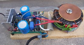
In the subsequent posts, I shall describe in detail each section of the circuit, but in the meantime here are a few pics of the build:


And this is the indoor unit:

To be continued.....
https://www.diyaudio.com/community/threads/automatic-resonance-frequency-finder.254384/post-3886008
http://www.diyaudio.com/forums/chip-amps/176052-now-regulator-chip-jlh-amp.html
http://www.diyaudio.com/forums/chip-amps/192934-se-class-regulator-chip-amp-madness.html
http://www.diyaudio.com/forums/chip...oss-tringlotron-regulator-chip-amplifier.html
http://www.diyaudio.com/forums/chip-amps/193214-class-chip-amp-now-complementary-version.html
http://www.diyaudio.com/forums/chip...ator-chip-amp-family-welcomes-new-member.html
http://www.diyaudio.com/forums/chip-amps/175457-just-fun-regulator-chip-amplifier.html
https://www.diyaudio.com/community/threads/yet-another-funny-chip-amp.280777/post-4476559
Here is another one to add to the family: it is a solar "helper". It has the ability to inject a modest amount of power into the mains, from an array of photovoltaic cells.
It is not a solar inverter: it has no oscillator or timebase, no synchronization circuit, and it is incapable of operating as a stand-alone power source.
But how can it work then?
That's where the chip-amp steps into play: it is configured as a power negative resistance, connected to the mains via a transformer, to adapt the voltage, and for obvious safety reasons:
The circuit is based on a TDA1512, just because I had one patiently waiting in a drawer: any other chip-amp or power opamp would be suitable (and probably preferable, because the TDA1512 has annoying quirks).
The load (the transformer's primary) is connected between the output and the - input, and the current is sensed by a low-value resistor (R8, R9). On the + side, a resistive divider (R3, R5) injects a positive feedback signal matching the voltage on the sensing shunt, to generate the negative resistance.
The negative resistance engine itself is minimally simple, but there are lots of auxiliary circuits around: they are needed for a smooth, effective operation. The project is small-scale, but fully fledged and is much more than a mere proof of concept: it has to handle all the possible situations, and behave gracefully and safely all of the time. This requires optocouplers, relay, etc.
It is a lot of circuitry for a meagre 10W (peak!) output, and a continuous operation for more than 10 or 20 years would be required to amortize the building costs (unfortunately this might be reduced to two or three years with the rocketing energy prices), but it is fun, and it could be upscaled relatively easily.
In the subsequent posts, I shall describe in detail each section of the circuit, but in the meantime here are a few pics of the build:
And this is the indoor unit:
To be continued.....
Let's start with the negative resistance core:
It is an audio amplifier, adapted to operate under peculiar conditions: the first one is unity-gain. To remain stable, the compensation network (C10, R10) is beefed-up, and a noise-gain network (R2, C1) is added.
In addition, the resistor R4 disables the internal voltage divider, as it interferes with the input circuit. R6 and R7 play the role of this divider, without the problems.
The diodes D1, D2 protect the output from load-dumping conditions (when the circuit is connected to the mains, but receives no DC supply).
C11 and R12 ensure that the load keeps a low impedance for high frequencies, despite the leakage inductance of the transformer: a negative resistance needs to see a smaller, positive one at all times to remain stable. The regular Zobel C12, R17 is also present.
Since the solar panel is a unipolar source, an internal virtual ground is created by C8 and C9.
For an optimal operation, the transformer's open voltage needs to match the maximum output swing from the IC. The transformer chosen was 7.5V nominal (and 50VA, which is overkill), but it delivered 8.5V unloaded, which was too much for the 24V panels. As I didn't want to dismantle the transformer, I simply added a few turns in antiphase to arrive at 6.5V.
There are various capacitors around: C3 to C7. They ensure a good DC stability, and they also center the operation on 50Hz: the I-V phase is 0°, and the gain is maximum for that frequency.
Initially, the circuit was designed as "agnostic", ie. aperiodic: it could cover a range from a few tens of Hz to a few kHz, but it required largish non-polar capacitors, and/or caused a DC offset multiplication, none of which is very appealing.
To adapt the circuit for 60Hz operation, you just need to use the next lower E12 value for all those caps.
Note that C16 is purely decorative: it is a remain of the previous version but I didn't want to butcher the board to remove it, and as it does practically nothing, I left it in place. I included it on the schematic for the sake of completeness.
Later, I will publish another version, with this cap removed and one or two improvements I noticed when drafting the schematic
I understand the humour behind the question, but it actually makes (some) sense: the core of the circuit is a parallel amplifier. If you connect the output across a speaker/amplifier combo, it will increase the available power.Hello,
My question is: how does it sound?")
With a tube amplifier having a matched impedance output, the level will actually increase; with a SS amplifier having a negligible output impedance, there will be no detectable difference, but the original amplifier will be helped by the Heliophile.
For example, if you have 4 ohm speakers and an amplifier rated for 8 ohm minimum load, you can configure the Heliophile to be a -8 ohm resistor. When paralleled with 4 ohm, it will result in a +8 ohm impedance, safe for the amplifier.
With this version, the sound would be extremely boomy, because it is centred on 50Hz, but the aperiodic version would be flat: the helping current that is injected is an accurate image of the voltage.
This is all theoretical though, and there are many caveats: speakers have a notoriously variable impedance vs. frequency, and this would cause troubles and instabilities.
I am not sure how safe and wise such an arrangement would be anyway: what happens if the amplifier or the heliophile is turned off, or if the speaker is disconnected?
Back to the Heliophile:
Lots of ancillary functions are required to make the Heliophile safe and useful.
Since the solar panels will be in the dark most of the time (as it is always the case), the mains consumption must fall to ~zero, otherwise any benefit gained during the day will be lost during the night.
A relay disconnects the transformer from the mains when the DC input is insufficient: Q1 and Q2 detect when the input is >27V, and drive the opto U1, which allows Q4 to drive the relay if the mains is present and sufficient. A hefty hysteresis is built into the detector, to avoid chattering: when the Heliophile becomes active, the DC voltage will drop to 24V or even lower, but the circuit has to remain active until the voltage is too low to be useful.
The relay is wired in a peculiar way: in principle, a simple SPDT would be sufficient, and the lightbulb shouldn't be necessary: the transformer could be shorted directly to keep the negative resistance happy.
However, such a connection can have dangerous effects if there no clear break-before-make action, and even so an arcing shoot-through between the two outer poles of the contact is always possible.
To prevent this issue, two separate contacts are used, and a lightbulb is inserted in the shorting path: a lightbulb can safely tolerate a voltage spike, and has a very low cold resistance to neutralize the negative resistance.
The mains-side of the auxiliary circuit is fed from a small capacitive supply, consuming a very low amount of active power.
As an additional precaution, the DC voltage detector also drives a muting switch in the form of a FET, J1 to defeat the negative-resistance action.
Before examining the rest of the support functions, here are some additional pics, first the indoor unit:
Then the result: the Heliophile is connected to a true wattmeter, based on first principles and using translinear circuits. It accurately extracts the active power, independent of the waveshape or the direction of the power flow.
Here, it indicates -9.7W, the power reinjected into the mains, a touch above the 50% efficiency mark.
When tuned exactly at the optimum, the Heliophile can deliver 10.5W, but it has been deliberately restricted to 9.5W: there is no power control other than informal, and aiming for a slightly lower power allows an operation for a wider range of lighting conditions: everything above 9.5W is simply wasted, and when the input is not sufficient to deliver 9.5W, the amplifier begins to clip (gently).
This adds some distortion to the waveform, but at such a low power level it poses no problem, and the clipping somewhat improves the efficiency.
Ideally, one would need an AGC, a servo driving the FET in linear mode, maybe a MPP controller, but this would vastly complicate the circuit for a very meagre result
Attachments
One part of the circuit still needs examination: the circuitry around Q3:
Q3 detects the absence of output current when an output voltage is present: if no significant current (<1.5mA) flows through D7, D8 but an output voltage is present, D9, D10 will allow Q3 to conduct, via D11, R24.
This conduction will be half-wave, enforced by D12, D14.
When Q3 conducts, the input of the opto D13 will be activated, forcing J1 to conduct. C2 filters the half-wave signal to obtain a continuous conduction.
The purpose of this circuit is to shut down the negative resistance when the output conditions are abnormal: when an AC output is present, power should flow one way or another.
If a voltage is present in the absence of current, it could mean that the heliophile has been unplugged, or that it does nothing useful (it is just in equilibrium), or else, but in any case it should become inactive until more normal conditions return.
All of this looks clunky and inelegant, but it is the result of an evolution: layers upon layers have been added to address possible or proven issues, resulting in a messy-looking but working circuit.
Ideally, an in-depth overhaul of all the auxiliary circuits would be needed to streamline them, but for a 10W peak output, it looks futile.
To make something really useful, the first priority would be an increase in power: I used 4 x 4.5W/6V solar panels, but a tenfold increase would be required to begin to make a difference on energy bills.
The second priority would be the replacement of the class B amplifier (theoretical efficiency 78%) with a class D amp.
A servo would be required for higher powers, and for a really high power, a MPP controller + solar tracker would be nice too.
Finally, the streamlining of the control would be a nice, final touch.
Anyway, this project works, even if it is very small scale, and it includes all of the elements required in a larger one.
Here is a possible evolution, in the light of testing and re-examination. It addresses the redundant capacitor, the DC accuracy in mute mode, and increases the hysteresis of the undervoltage detector:

Have fun!
Q3 detects the absence of output current when an output voltage is present: if no significant current (<1.5mA) flows through D7, D8 but an output voltage is present, D9, D10 will allow Q3 to conduct, via D11, R24.
This conduction will be half-wave, enforced by D12, D14.
When Q3 conducts, the input of the opto D13 will be activated, forcing J1 to conduct. C2 filters the half-wave signal to obtain a continuous conduction.
The purpose of this circuit is to shut down the negative resistance when the output conditions are abnormal: when an AC output is present, power should flow one way or another.
If a voltage is present in the absence of current, it could mean that the heliophile has been unplugged, or that it does nothing useful (it is just in equilibrium), or else, but in any case it should become inactive until more normal conditions return.
All of this looks clunky and inelegant, but it is the result of an evolution: layers upon layers have been added to address possible or proven issues, resulting in a messy-looking but working circuit.
Ideally, an in-depth overhaul of all the auxiliary circuits would be needed to streamline them, but for a 10W peak output, it looks futile.
To make something really useful, the first priority would be an increase in power: I used 4 x 4.5W/6V solar panels, but a tenfold increase would be required to begin to make a difference on energy bills.
The second priority would be the replacement of the class B amplifier (theoretical efficiency 78%) with a class D amp.
A servo would be required for higher powers, and for a really high power, a MPP controller + solar tracker would be nice too.
Finally, the streamlining of the control would be a nice, final touch.
Anyway, this project works, even if it is very small scale, and it includes all of the elements required in a larger one.
Here is a possible evolution, in the light of testing and re-examination. It addresses the redundant capacitor, the DC accuracy in mute mode, and increases the hysteresis of the undervoltage detector:
Have fun!