MR-123A DHT transmitting triodes. AKA FR-123A

Amperex MR-123A DHT transmitter triodes, aka FR-123A. Four of them.
Similar specs as 211, 845, trioded 813, etc. 1kV-1500V plates, 10kohm OPT... With minor mods (top cap for plate) these can be rolled in 211 and 845 amps.
These are unused but the boxes rotted away so they have no box. Carefully packed into a relatively solid cardboard box. Ships from Norway, so that is probably coming at 100USD for non EU, and perhaps 50EU for EU.
Will make a great DHT SET amp at roughly 20W output. I just don't have time so want them to find a new home...
Asking 600USD for all four + shipping. OBO...
Compare to new Chinese 845 and 211, or other NOS 211s and 845s on ebay this is a great deal! Besides if I don't sell, eventually I can build an amp with them, I just don't have time for a long while and if good offer (600USD) I will let them go... (I have them on 'bay for 800USD)

Attachments

  • IMG_2672.JPG
    IMG_2672.JPG
    546.3 KB · Views: 102
  • IMG_2673.JPG
    IMG_2673.JPG
    599.5 KB · Views: 108
  • IMG_2674.JPG
    IMG_2674.JPG
    749.9 KB · Views: 125
  • IMG_2675.JPG
    IMG_2675.JPG
    669.8 KB · Views: 105
  • IMG_2676.JPG
    IMG_2676.JPG
    458.9 KB · Views: 137
  • IMG_2681.JPG
    IMG_2681.JPG
    773.7 KB · Views: 110
  • IMG_2682.JPG
    IMG_2682.JPG
    453.5 KB · Views: 111
  • IMG_2683.JPG
    IMG_2683.JPG
    484.6 KB · Views: 101
  • IMG_2684.JPG
    IMG_2684.JPG
    462.6 KB · Views: 96
  • IMG_2685.JPG
    IMG_2685.JPG
    461 KB · Views: 105
  • IMG_2686.JPG
    IMG_2686.JPG
    579.4 KB · Views: 109

Speakers transformers ideas

Looking to build smallish portable set.

Powered by Bluetooth 2.1 amplifier with batteries .
The idea is to have 2 speakers being joint most of the time to carry around easily but also be able to separate both of them when I want to hear stereo.

So what are some ideas for locking mechanisms to join the two speaker boxes. I am thinking of having a sub that might also be attached at the bottom of the two speakers
The sub I'll probably not carry around too much..
Speaker boxes are around 6x6x 12 each.

The cheapest might be using wellpro to join 2 speakers but was hoping to find something slicker

Mute function on LM4780

Please, please forgive the newbie amateur post. I purchased some of the red LM4780 boards designed by Peter Daniel and Brian GT many years ago. When I turn on the power, you can hear a soft turn-on thump, but it will not pass signal. I assume the chips are in muted mode. After looking at the datasheet, I am still unclear as to the method of disabling the mute, so the amp stays on. Pins 14 and 20 are the mute pins; do I apply voltage or ground to turn off the mute?

How much above Fs should a new driver be?

Hi all - just took delivery of a new pair of Faital Pro 10PR320-16 drivers, and was surprised to measure fs at 65 & 68 for the two drivers (out of the box) when spec fs is quoted at 50Hz.

They've come down a bit (both to c 60Hz) after a few hours of burn in - but on last measurement they had both stopped changing.

Is this level of difference (c.20%) from specs normal for Faital drivers? Given I need a pair of 50hz drivers, I am feeling a bit hard done by.

Anyone have any thoughts?

Ultrasonic noise with Class D

We just discussed ultrasonic noise from Class D amps in a different thread but it would probably fit better here.

It seems people are concerned about Ultrasonic noise polution and I want to have a look into that. So it's about HF noise through your speakers from left over switching frequencies (and every design has some of that).
So I made a few quick measurements with an amp of mine based on Hypex NCore. HF peak is at 70kHz and up to 20uV there, summed from 10-90kHz it's about 600uV. 10-20kHz it's about 19uV (15uV(A)) - so the main part of this is actually HF from 20kHz to 60kHz.

So in my opinion that's absoutely no concern about! Actually you have to search hard for tweeters which will do anything at 70kHz (Bliesma T25B can do this).

But there are so many Class D designs out there - what are your experiences and measurements? How doe ICEpower and Pascal modules do in this regard? Or cheaper chip designs? Any measurements available?

FFT.png
RMS Level fulll range.png


RMS Level 20kHz.PNG
RMS Level 20kHz (A).PNG

New Markaudio offerings

Has anyone reviewed or looked at the new Alpair 7MS or 10M?
Also what are people using for cabinet construction since Baltic birch has disappeared from the Market place?
Rockler has American birch plywood in 3/4" 24"x48" in stock & 1/2" on back order into January- is this a good substitute?

Would the new 7MS work well in the Slim Classic GR dMar-Ken7.3 2v03 cabinet? I used this cabinet for the 7P & it turned out very well. I do keep it out of direct sunlight.
I have 3 sheets of 1/2" Baltic birch I intended to use for the Aplair 7 that I missed buying and now currently unavailable, replaced by the new 7MS.
I veneer 1/4" cherry over the Baltic birch to achieve 3/4" for cabinet density and 3/8" round for the driver opening.

I have not been active on the site since before the Alpair 7 was discontinued & Baltic birch has been hard to find.

Itch'en to start a new speaker project for the Livingroom.

A year ago lost a month apart to the day a father-in-law from Covid & brother-in-law as a collateral death- could not find an open ER due to ER's being too full to see him in time & he bled out from a non Covid health event.


Hope others here have faired better and are in good health.
Thanks in advance. Happy Holidays present & forthcoming....

Resistor replacement ??

Hello everybody happy thanksgiving ! i have a question about some resistors using in my old speaker ..... I was try to swap some old oxy cable inside and had a chance took out both crossover out of the speaker and found out the manufacture had used two difference brands of resistors in midrange drive section L and R crossovers ......had measure for all the resistors, fortunately they all had the same value , they are in Series 1.3ohm 20w x 3 .. 3.9 ohm total , i feel weird and bad why they did that ?? I think i have to change it. go to the store , the only had 1.2 ohm 20w and 1.5ohm 20w in stock , should i go for it ?? using 2 x 1.2 ohm + 1.3 ohm ?? or go for all 1.2 ohm x3 , sound may be difference ?? please suggest. Thanks .

Old Odd But Interesting Phase Inverter Circuit

While browsing through some old Audio magazines I came across this article for an amplifier which uses a three triode phase inverter. Since I like the Van Scoyoc cross coupled inverter, this one stood out. The author has a patent on it (below), but uses a modified version. Here's the article. Thought someone might be interested.

I also saw an amp that uses this version but with type EFP60 secondary emission tubes. I have some of those but no sockets. They're a strange looking loctal style but with 9 pins.

Attachments

For Sale MiniDSP DDRC-22W and several drivers (Audio Technology, Usher, Scan-Speak)

I’m in the process of moving so it’s time to list some excess after figuring out what I’ll need for two speaker builds. Shipping from MA but would prefer pickup for the drivers because I don’t know how well they’ll survive the trip. I have no idea what to price the drivers at so I’ll list them at 75% retail at most, or parity with used market for anything I can’t find new. I would be glad to do bundle offers.

1. MiniDSP DDRC-22A: Works perfectly, comes with UMIK and I can help the buyer with dirac license transfer. $319 plus shipping.

2. Audio Technology 4H520613SD - Works great, just not what I’m looking for (I’m using a similarly sized C-Quenze version). 270 euro each new, listing at $400 $300 $250 $225 for the pair.

3. Audio Technology 6H521706SD - also works great, using the 8 inch version instead. 400 euro each new, $600 $450 $375 $325 for the pair.

4. Usher 8945A - a little dusty but works great. $130 each new, $195 $125 for the pair.

5. Unknown Usher 7 inch - I don’t know what these are. The box says 8836AC but these are definitely paper. The 8836AC was cleared out for $49 each so I can do $80 $60 for the pair if you buy another pair.

6. Scanspeak 21W/8554-00 - Probably needs to be refoamed. I’ve seen people sell them for $200 a pair but if you buy another pair of drivers I can do $125 $100.

3C459E3E-3193-49E9-972D-D404AB9DB81B.jpegF2636BC7-10DE-4272-9997-49F3BDA3517D.jpeg59E7DEE0-F5F9-4AB3-9FA8-4245A5DB08D5.jpeg358791C7-047D-4AD8-A239-1777673752E5.jpeg928BDC84-2A5A-4497-B9A0-6BB104CCB014.jpeg7E5AA2CF-4754-4084-B4EA-01B938895DDE.jpeg91DECC05-B74E-49EB-8680-BD8C4F2DB654.jpeg

For Sale First Watt M2 Clone Boards (Tea Bag) Fully Populated & Tested

These M2 boards came out of a working amp a couple years back. Just to be safe, I recently inspected, cleaned (some residual flux), bolted them to heat sinks, and tested on the bench...they work fine. They have the Harris 9240s installed. Also, they have Faston 110 spades installed (input, output, ground etc.). I can remove the Fastons if you like. Asking $100 plus shipping. I'll include the Tea Bag PS board as well.


IMG_4188.JPGIMG_4190.JPGIMG_4189.JPGIMG_4187.JPGIMG_4191.JPG

how can you convert a speaker out to line level out?

i have some older analog sources i would like to connect to my mixer (portable record players / reel to reel players) that only have speaker outputs.

when plugging these into the mixer, the signal is way to loud and causes a lot of overdrive - and when i turn the volume down enough to get rid of the overdrive i get some sort of tone that drowns out the signal.

so i figure i must need to create some sort of box that i can plug in-between the units to convert the speaker out into a line level out - how can i go about doing this?

can you make a universal box that i could use with all my units (maybe with a pot to determine how much the signal is attenuated?) - or would you recommend modifying all the units internally somehow?

thanks for your help on this

For Sale SB Acoustics Satori MW16P-8 speaker drivers (4 pieces)

Due to the cancellation of speaker project, I have for sale 4 SB Acoustics Satori MW16P-8 speaker drivers. All speakers units are like new, used only for few tests. Selling in pairs only.

Price: SOLD

Not responsible to any import duties, taxes, customs fees!

Attachments

  • MW16 1.JPG
    MW16 1.JPG
    227.1 KB · Views: 131
  • MW16 2.JPG
    MW16 2.JPG
    187.9 KB · Views: 136
  • MW16 3.JPG
    MW16 3.JPG
    177.9 KB · Views: 136

Question about a setup

Hi,

As I have little knowledge around this topic I would like to ask a question and seek advice.

The system that I am about to buy is made out of these 3 components:

-Onkyo TX-NR 6050 receiver
-KEF - Q Series 6.5" 2-way Bookshelf speakers (pair)
-Audio Technica ATLP60 XBT Bluetooth stereo turn table


1) the receiver model and brand I wrote would work fine with those speakers?

2) the turntable would also run with the receiver I hope. is this fine ?

3) what kind of subwoofer would you recommend that works well with this receiver and speakers?
I checked the nearby stores where I live and these are the available products it seems I can choose from that fits my budget:

Polk Audio PSW108 10" Powered Subwoofer
Polk Audio PSW10 10" Powered Subwoofer, 100W
Klipsch - Reference Series 10" 150W


Thank you all for your recommendation
Cheers

Pre amp for MOFO

Hi,

I was thinking of a design for the MoFo that that could operate from the Mofo power supply itself. The only problem is the pre amp swing needs to twice that of the MoFo to fully run it. I was looking at using an inductor based as well, similar to the LÁmp Inducted but with negative feedback utilising a IRF610. I was planning on biasing it at about 100mA. The inductor can withstand up 150mA.

Just wanted your opinion on if it would work.

Circuit is as attached.

Attachments

  • 20221125_112007_copy_984x685.jpg
    20221125_112007_copy_984x685.jpg
    67.4 KB · Views: 209

Shield and ground layer intercapacitance?

So i had an idea for a 4 layer board designating one layer as shield (or call it earth) layer that will fasten directly to the chassis, and the dc ground plane connecting to this layer at only single point. I can see how the shield layer would benefit pwr and signal traces but for a ground layer perspective wouldnt it just look like an antennae/oppportunity for a lot of parasitic capacitance? And is that actually still benefitial for audio?

Ifi Zen Phono power supply upgrade

Good morning everyone. Some time ago I bought the IFI ZEN PHONO phono preamplifier.
I am satisfied with its performance. If I compare it to other preamps I've had, it seems pretty good.
The only thing I have noticed is its low output level when using the MM selection (36dB), but I have solved it by using its balanced output that adds 6dB of gain.
I have seen that there are power supplies for sale with better features than those that come in the original package and that, according to what they say, improve their performance.
My question is: since it is powered by a 5 volt source (which later becomes +12 -12 volts with an internal switching source), could a 10000 mA power bank be used instead since it also supplies 5 volts?
It would be 5 volts DC pure, without the ripples and interference of the network.
Would it be an improvement compared to the wall wart that it originally brings?
Cheers

How works Capsule Mic & Preamp

Hello everyone

I'm struggling to understand how works a capsule/condenser mic , I would like to design a pream based on the THAT1512 ( see attached )

First question : What kind of stage is there in the body of the mic ? , I mean, is there a pre-preamp just for the capsule ?

In the schematic attached below i guess the capsule is not wired on J1 ?

if i would like to desing a PCB where evething would hold into the body of the mic , a 3 pins XLR would not be enough ?

Thx you for your advices

Attachments

  • ss-That-Thing.jpg
    ss-That-Thing.jpg
    149.8 KB · Views: 140

Desktop Transmission Line

Hi, first post. Interested in making some small desktop transmission line speakers with a full range driver. Only 300mm high but want to know driver size and recommended spec.
Bit of a transmission line fan owned a couple over the years and have a pair of PMC Twenty 23 now. Never made a speaker before but have built a Bottlehead Crack headphone amp some years back.

For Sale "RARE" NEW OLD STOCK (NOS) GENUINE SANKEN / NEC / TOSHIBA / MATSUSHITA / PECOR

WTS: "RARE" NEW OLD STOCK (NOS) GENUINE SANKEN / NEC / TOSHIBA / MATSUSHITA / PECOR
( Sansui / Luxman / Pioneer / Accuphase..etc)

PRICE : Usd $10.00 each (World Wide Shipping included)

Accept Paypal ; vintagerepairparts@gmail.com

Email me to purchase: vintagerepairparts@gmail.com

Thank you, HAVE A NICE DAY.

SANKEN
2SA745 - 6 UNIT
2SA747A - 6 UNIT
2SA744 - 11 UNIT
2SC1403 - 5 UNIT
2SC1116A - 3 UNIT
2SC1116 - 1 UNIT

NEC
2SB539 - 5 UNIT
C2337A - 2 UNIT
A1007A - 12 UNIT

TOSHIBA
2SB531 - 17 UNIT
2SB554 - 20 UNIT
2SB557 - 18 UNIT

PECOR
MJ2955 - 4 UNIT

MATSUSHITA
2SB481 - 39 UNIT @USD6.00 ea

$ logo
2SC2323 - 13 UNIT

MOSPEC
MJ15004 - 1 UNIT

Attachments

  • 2SA744.jpeg
    2SA744.jpeg
    47.3 KB · Views: 168
  • 2SA745.jpeg
    2SA745.jpeg
    35.9 KB · Views: 149
  • 2SA747A.jpeg
    2SA747A.jpeg
    55.2 KB · Views: 149
  • 2SB481.jpeg
    2SB481.jpeg
    85.5 KB · Views: 214
  • 2SB531.jpeg
    2SB531.jpeg
    80.9 KB · Views: 146
  • 2SB539.jpeg
    2SB539.jpeg
    66.5 KB · Views: 148
  • 2SB554.jpeg
    2SB554.jpeg
    62.4 KB · Views: 149
  • 2SB557.jpeg
    2SB557.jpeg
    83.5 KB · Views: 177
  • 2SC1116.jpeg
    2SC1116.jpeg
    23.7 KB · Views: 140
  • 2SC1116A.jpeg
    2SC1116A.jpeg
    30.4 KB · Views: 150
  • 2SC1402.jpeg
    2SC1402.jpeg
    46.7 KB · Views: 445
  • 2SC1403.jpeg
    2SC1403.jpeg
    44.1 KB · Views: 154
  • 2SC2323.jpeg
    2SC2323.jpeg
    75.9 KB · Views: 166
  • A1007A.jpeg
    A1007A.jpeg
    48.6 KB · Views: 193
  • C2337A.jpeg
    C2337A.jpeg
    34.8 KB · Views: 128
  • MJ2995.jpeg
    MJ2995.jpeg
    55.3 KB · Views: 176
  • MJ15004.jpeg
    MJ15004.jpeg
    35.1 KB · Views: 142
  • Like
Reactions: yogiDIYbear

Sealed box midrange loading 6 drivers in one Vb

Hey,
I am building a fully active / DSP controlled system, the midrange uses a line array of 6 dedicated mid drivers.
To achieve my target performance each driver models best in a 10 litre sealed box, so far so good!
My question is regarding the cabinet loading of the drivers... What are the pros and cons of 6 individual sealed chambers Vs all 6 drivers sharing one sealed chamber of 60 litres?

Please ignore the better cabinet rigidity using 6 sealed chambers Vs one large box and the corresponding savings in labour and materials.
Thanks in advance!
Alex.

Burned Power Supply PCB's in Pioneers SX Series (727-828-939-980-1050-1080-1250-1280-1980) let's make things better ??

In the attachment there are some images from PS-PCB's of Pioneer's vintage receivers from the 70'. Main reason therefore is the fact, that no chassis mounting for the TO220 parts was realized - instead this only mounting on a actually too small heat sink.
All images in the web after performed refurbishing procedures show the same result - this means that thermal stress continues to occur during operation. This I don't like.
With the SX-939 I plan to screw the TO220 parts onto the chassis in order to achieve better cooling properties.
Maybe there are user's that have done this in such a kind and can upload images - thank you very much.

Attachments

  • Pioneer SX-1250 Power Supply PCB-III.jpg
    Pioneer SX-1250 Power Supply PCB-III.jpg
    518.3 KB · Views: 242
  • Pioneer SX-1250 Power Supply PCB-II.jpg
    Pioneer SX-1250 Power Supply PCB-II.jpg
    493.5 KB · Views: 202
  • Pioneer SX-1250 Power Supply PCB-I.jpg
    Pioneer SX-1250 Power Supply PCB-I.jpg
    468 KB · Views: 232
  • Pioneer SX-1280 Power Supply PCB-I.jpg
    Pioneer SX-1280 Power Supply PCB-I.jpg
    368.4 KB · Views: 231
  • Pioneer SX-1050 Power Supply PCB-II.jpg
    Pioneer SX-1050 Power Supply PCB-II.jpg
    256.4 KB · Views: 192
  • Pioneer SX-1050 Power Supply PCB-I.jpg
    Pioneer SX-1050 Power Supply PCB-I.jpg
    261.4 KB · Views: 196
  • Pioneer SX-1280 Power Supply PCB-I.jpg
    Pioneer SX-1280 Power Supply PCB-I.jpg
    368.4 KB · Views: 180
  • Pioneer SX-1980 Power Supply PCB-III.jpg
    Pioneer SX-1980 Power Supply PCB-III.jpg
    136.1 KB · Views: 211
  • Pioneer SX-1980 Power Supply PCB-II.jpg
    Pioneer SX-1980 Power Supply PCB-II.jpg
    630 KB · Views: 234
  • Pioneer SX-1980 Power Supply PCB-I.jpg
    Pioneer SX-1980 Power Supply PCB-I.jpg
    119.8 KB · Views: 240
  • Pioneer SX-828_Power Supply board_Before_03.jpg
    Pioneer SX-828_Power Supply board_Before_03.jpg
    358.3 KB · Views: 194
  • Pioneer SX-828_Power Supply board_After recap.jpg
    Pioneer SX-828_Power Supply board_After recap.jpg
    304.8 KB · Views: 188
  • Pioneer SX-828_Power Supply board_Before_01.jpg
    Pioneer SX-828_Power Supply board_Before_01.jpg
    499.7 KB · Views: 175
  • Pioneer SX-939 Power Supply Board-II.jpg
    Pioneer SX-939 Power Supply Board-II.jpg
    108.8 KB · Views: 182
  • Pioneer SX-939 Power Supply Board-I.jpg
    Pioneer SX-939 Power Supply Board-I.jpg
    129.9 KB · Views: 190
  • Pioneer SX-727_Power Supply Board-II.jpg
    Pioneer SX-727_Power Supply Board-II.jpg
    325.4 KB · Views: 174
  • Pioneer SX-727_Power Supply Board-I.jpg
    Pioneer SX-727_Power Supply Board-I.jpg
    297 KB · Views: 162
  • Pioneer SX1010 PS-PCB.jpg
    Pioneer SX1010 PS-PCB.jpg
    115.8 KB · Views: 165
  • Pioneer SX1010 PS-PCB-II.jpg
    Pioneer SX1010 PS-PCB-II.jpg
    54 KB · Views: 171
  • Pioneer SX980 PS-PCB.jpg
    Pioneer SX980 PS-PCB.jpg
    9.5 KB · Views: 191

10” MTM design help

In the process of making my own design with components made in U.S.A as one of my guidelines (hope thats not considered political?) Just got a smokin deal on 12 of these custom ordered eminence 10” (based on delta 10b) with cast frame/altered specs. (see pic below for specs.)
These model in a sealed 2 ft3 box (see pic below for curve) perfectly for 60hz hp and 1400hz(+/-) lp

plan to use them with n314x-8/h14ea combo……and maybe a ported lab12 bass bottom (as in stackable)

Then it dawns on me that these 10” custom specs kindly lend themselves to a TL setup, i’m slightly versed in how they work (have read some Martin King and others stuff) and seeing as how i have enough woofers to make 3 pairs of mtm’s why not try some different stuff and choose/keep whats best for my room and sell the others locally.

So question is can the collective knowledge here help guide me in getting a TL box going? See pic below for what i’m thinking (imagine the tweeter as a horn!)
i need to know the desired bottom limit and then base length on 1/4 wave, is there a way to calculate bottom useable frequency from driver specs? I’ve read (unless i interpreted wrong) that you will get 1/2 as much of driver fs lower? Also port opening needs to be equal to sd of both drivers? Also that tapered works better for resonances but is more complicated to get right?
I read if you taper (big chamber to smaller exit) it needs to be 3:1 so if straight with 3 channels (as in pic) would it go 3-2-1 ratio? And is there a formula for starting/main chamber size?

Thx Bob

Attachments

  • FD680A90-2C93-4388-B6BF-623EDD3E143A.png
    FD680A90-2C93-4388-B6BF-623EDD3E143A.png
    136.1 KB · Views: 185
  • 59C683B4-89CA-4962-AB2D-9D292A37AB8C.png
    59C683B4-89CA-4962-AB2D-9D292A37AB8C.png
    113.6 KB · Views: 187
  • 66293F16-7A7B-4728-B936-63E8D1A43FC7.png
    66293F16-7A7B-4728-B936-63E8D1A43FC7.png
    381.9 KB · Views: 190

Building a Aikido preamplifier

Hi!

I have built some tube amplifiers, so now I want to build a preamplifier!
Preamplifier and linestage is the same thing, right?

This is what I am looking for:
*Low Distortion
*Low output impedance

Then I read about the Aikido 🙂

http://www.tubecad.com/2004/blog0011.htm
http://www.tubecad.com/2005/January/blog0030.htm

So I started with the enclosure:
It's a modified printerswitch in aluminium 🙂

An externally hosted image should be here but it was not working when we last tested it.

An externally hosted image should be here but it was not working when we last tested it.

An externally hosted image should be here but it was not working when we last tested it.

An externally hosted image should be here but it was not working when we last tested it.


The tubes are 6N1P:s and 5687:s!
But a friend told me, he had bought pcb:s and in the documentation there was another shematic, not the one I found. He is using the same tubes...
His schematic was called "Revision A Line Amplifier" It was a bit different, so I wonder:

Which schematic shall I use?
I want to use the best one! 😉


ps. I don't want to use pcb:s. That's uncool 😉

Balancing my Hifi: Croft Super Micro Pre amp with QUAD 606

(Mods: feel free to move this post if it's the wrong place, it doesn't neatly fit into tube or solid state as it's about the balance between them both!)

Hi everyone, I have the following hifi setup.

Turntable w/ AT440mlb cartridge & stylus
Preamp: Croft Super Micro
Amp: Quad 606mk2

The noise floor is getting quite high and it periodically makes weird crackling sounds. I suspect the valves in the pre have had their day and the 606 could do with recapping (1 of the 4 main caps is different to the others - suggesting it's been half(quarter?)-jobbed at some point before my ownership.

I want to take this opportunity to make any worthwhile modifications to it, specifically:
  1. I'd like to match the Output Sensitivity of the Pre to the Input Sensitivity of the Amp.
  2. Ensure their is appropriate loading for the stylus
  3. Balanced the difference in gain between between the line level inputs and the phono input.
One, is balancing the sensitivities a simple case of matching the numbers together? I keep reading that Croft Pre-amps have a high gain however I can only find the stats online for the Croft Micro 25 which has a states output sensitivity of 0.5mV and the Quad 606's input sensitivity is also 0.5v. So is there anything to do here?
  1. https://www.dadaelectronics.eu/uplo...vice-Manuals/Quad-606-Service-Manual-V2.0.pdf
  2. (this is for the Micro 25) https://web.archive.org/web/20210922142521/http://www.croftacoustics.co.uk/micro25.html
Two, the AT440mlb cartridge apparently has a recommended load impedance of 47k ohms; I am not an EE person, but according to this schematic the Croft Super Micro has a 47k resister on the phono input - does that mean the pre amp is ideally suited to the stylus as is? What about input capacitance, is that "tuneable"?
  1. http://soundmovements.co.uk/diyaudio/Croft_SM_III_circuit.gif
Three, when I play from the phono sources the output level is considerably higher than if I play the same music from a line in source. For all of my sins, this usually a line in from the headphones out of my iPhone for casual/background listening - I promise!

I have no intention of carry out these modification myself, I have an amp tech I have used before - but he tends to do what you instruct him and no more, so I want to be quite specific about the work I want carried out.

Thanks for any advice in advance!

Tube preamp for car

Hello, I would like your opinion on building a tube preamp for my car, this is going in the head console which is something I have never seen before, each parts has to be under $50. So far I've been looking at a few ebay/aliexpress kits, let me know your thoughts, thanks.

Kits so far:
https://www.ebay.com/itm/313757694352?var=612529018280
same kit but on Aliexpress: https://www.aliexpress.com/item/2255799850275299.html?spm=a2g0s.8937460.0.0.fa832e0eg3hQZ8
https://www.ebay.com/itm/325203864221?var=514101376212
https://www.ebay.com/itm/125318368510
https://www.aliexpress.com/item/2251832832888687.html?spm=a2g0s.8937460.0.0.fa832e0eg3hQZ8
https://www.aliexpress.com/item/2251832694961293.html?spm=a2g0s.8937460.0.0.fa832e0eg3hQZ8

Attachments

  • Tube Preamplifier Board _ Kit Base on Hetian Mao's Circuit Hifi.png
    Tube Preamplifier Board _ Kit Base on Hetian Mao's Circuit Hifi.png
    145.2 KB · Views: 181
  • 1DIY LITE LS60 balanced Tube preamplifier board _ balance preamp kit.png
    1DIY LITE LS60 balanced Tube preamplifier board _ balance preamp kit.png
    109.6 KB · Views: 172
  • DC (DC12V) Car & Home 6N4 (12AX7) Horseshoes Bile.png
    DC (DC12V) Car & Home 6N4 (12AX7) Horseshoes Bile.png
    176.7 KB · Views: 162
  • CSR8675 Bluetooth 5.0 Audio Receiver Board ES9018.png
    CSR8675 Bluetooth 5.0 Audio Receiver Board ES9018.png
    122.8 KB · Views: 152
  • DC12V 6N8P (6H8C 6SN7) Vacuum Tube Car Audio Pre Amplifier HiFi Preamp Board.png
    DC12V 6N8P (6H8C 6SN7) Vacuum Tube Car Audio Pre Amplifier HiFi Preamp Board.png
    144.2 KB · Views: 174

Honey Badger 2.4 Populated Boards

I have a set of Honey Badger boards that I put together. I used it for a few weeks before eventually having a thermal runaway problem. I was told that it simply was not possible with this design and But I'm not able to troubleshoot it myself.

Nothing smoked but it got quite hot. I don't know if any parts got damaged.

Whoever buys it needs to be able to troubleshoot. I haven't tried to use it since having a problem. I also have 12 Panasonic 8200uF caps, and a DIY Audio soft start and DC protection circuit. This was all bought new in 2014. Everything is sold as-is.

Price updated to $150 US shipping included anywhere in North America.

DSC07571.jpg


DSC07572.jpg


DSC07577.jpg


DSC07574.jpg

FS: AD844,OPA627,AD797,LT1028...

Hi, I am selling the following items. They are used "genuine" parts but in good condition. Most of them are pulls from precision instruments. All op amps are tested before shipping. Shipping is $5 worldwide for up to 50g.

Used parts:
BUF03FJ (TO-99) $5.5ea ->6pcs. DIP converted (including the DIP converter board).
Signetics NE5534A/BPA (DIP) $10ea ->only 4pcs. military grade. very hard to find.
ADEL2020 (DIP) $1.5ea
AD844AN (DIP) $1.5ea ->best for I/V. Read the AD844 thread.
OPA627AU (SOIC) $2.5ea
AD797A (SOIC) $3.5ea
LT1028 (SOIC) $1.5ea ->ultra low noise op amp.
LT1763CS8-5 (SOIC) 20pcs $2ea ->ultra low noise +5V LDO, excellent for digital receivers

NEW TDK C4532C0G1H224J320KA MLCC, 1812, C0G, 50V, 220NF/0.22uF $0.4 ea. Check here
NEW Single SOIC-to-DIP OP adapter 1cm x 1cm (include 8 high quality golden pins from Taiwan) $1 ea.
NEW Dual SOIC-to-DIP OP adapter board 1.2cm x 1.2cm (include 8 high quality golden pins from Taiwan) $1 ea.
*convert two single soic ops into one dip dual op


S5534A-2017-6-11.jpg


BUF03FJ-2017-6-11.jpg


OPA627AU.jpg


AD797-2017-6-11.jpg


LT17635.jpg


ADEL2020.jpg


AD844AN.jpg


LT1028CS8.jpg

OmniDirectional - work in progress

I've been working on a pair of Omni's. I'm looking for a different listening experience that is closer to the way real natural instruments project sound and use the room. I am willing to post pictures, and test results to share what works or doesn't, hoping for some insight and suggestions to improve it.

The starting point is this simple 2way setup. There were initial problems with them, but I'm enjoying them now, wanting more improvements. I'll post the those issues and my solutions up to where I am now.

Index to versions:
V1 : starting point, LR4 XO, soft dome tweeter with reflector, 32L BR woofer
V2 : circular waveguide with compression driver, 32L ABC woofer, new cones
http://www.diyaudio.com/forums/multi-way/303941-omnidirectional-work-progress-4.html#post5000878
V3 : circular waveguide, 16L BR woofer, new cones
http://www.diyaudio.com/forums/multi-way/303941-omnidirectional-work-progress-10.html#post5051183
V4 : circular waveguide, 16L BR woofer, same cones, new outer shell to reduce diffraction
http://www.diyaudio.com/forums/multi-way/303941-omnidirectional-work-progress-14.html#post5118639
V5 : new 16L sealed chamber, new discs and cones, added notch filters, same drivers as previous, using all previous lessons learned OmniDirectional - work in progress

Attachments

  • DSCN1829 reduced.jpg
    DSCN1829 reduced.jpg
    360.1 KB · Views: 1,979

Exposure 2010S2 remote controller

Hi All,

I have the Exposure 2010s2 integrated amplifier, it's remote controller gone missing and I'm looking for a universal remote controller that can control the amplifier, any suggestion for a remote controller?
Or....I know that some brands use the same remote controller protocol as others, long time ago I had a Marantz NR-1604 receiver that every time that I changed the volume it used to change my Naim Nait XS volume as well, does anyone have an idea if Exposure use the same protocol of another brand ?

Thanks

Suggestions on speaker build for two specific locations

Hi, I've got two venues that I'd love to improve the PA system at, preferably with the same set of speakers (though being modular may solve this). My primary goal is to improve sound clarity. I've only built home-audio and car audio (sq not spl) speakers systems in the past, but have done a medium amount of live-show sound. I'm familiar with hornresp (though not an expert) and the principles of quarter-wave designs.

Space 1: This is an intimate 180-seat theatre with circular wood-panel walls, high ceiling, large stage (at least 30% of the space is the stage), gently sloped and well-padded seating.
inlet-theatre-rental-guide-2018-19-8883577-8.jpg

Screenshots_2022-11-03-08-23-37.png

I'm involved in putting on some hall-of-fame level acts here, but the house speakers are leaving me wanting.

Space 2: It's an outdoor bandshell (~40ft wide) at a flat grassy park with 100m² of space. The shows here are afternoon events with lawn chairs setup, not densely-crowded, mostly classic rock, blues, and jazz.

Both spaces have rigging available.

So my question is, where to start researching?

Are multi-entry horns the de-facto build around here for sound clarity at volume?

Are there brands or driver lines that are much higher regarded than others?

I'm open to almost any budget plan below ~$4k at this point, and I understand the challenge of the two vastly different acoustic environments. A compact-ish setup would be nice, but certainly not a limiting factor at all. Sound quality is the main goal while meeting the SPL needs of each space.

HELP? Screw Sizes - Krell KSA100S - American Sizes

HELP? Screw Sizes - Krell KSA100S - American Sizes

I am based in South Africa and we use the metric system. I need to contact suppliers to get a couple of screws thats missing from a Krell KSA100S that I am restoring.

How do I communicate the sizes? The fractions are one thing as well as the No. size. But I am concerned about the thread pitch/coarseness?

There is basically a couple of screws missing for each type.

Odd question but any help will be highly valued. I am in a remote area and cannot simply visit a supplier. Africa...

Linn LK100 issue

Hi,

I'm using a Linn LK100 (1995) with improved Capacitors on the power supply.
It performed great for a few years and now suddenly started going crazy.

After switching on, it plays great with power and oomph and all. Suddenly after a few minutes it dies out. No sound on Left or right speakers.
Dying out is pretty fast, but no 'click or pop' noise. Just as if someone had switched it off.

Switching it off (via the button) after it stopped playing has no effect, until about ~10-20 seconds after switching it off (pressing the On/Off button) - it suddenly plays for a few more seconds and then dies out.

After measuring, I can say that the Toroid transformer receives the mains power and outputs two +33 VAC (Vs. common ground) voltage.
On the PCB it says '86V' next to it...

Any hint on what I should replace?

I would think that the capcitors on the AC-to-DC (power supply) part which seems to be common for both sides are not working OK.

Any other ideas or directions?

PSUD2 Transformer Source Resistance

Tube rectifiers often specify the minimum resistance required in series with each rectifier to limit peak current. For a full-wave supply, is the PSUD source resistance for the whole secondary winding or, as with the voltage, one half of the winding?

I have used PSUD2 with Ubuntu for a while now, installed with "PlayOnLinux" . A problem created by Ubuntu imposing the snap version of Firefox is that the PSUD help files are not available from within the program.

Pioneer RT-707

Before I place it on ebay, I will ask here. I am willing to part with my favorite rtr. I have digitized all my valuable reels and do not listen to it often enough to keep it. I hate to pack it and ship it, but if someone is willing to pay for substantial shipping charge, since its heavy, no problem. I would prefer if someone picks it up or i deliver within 50 miles of Washington DC. I am in Germantown, MD.
Pioneer RT-707 is in great working shape and sounds awesome. Heads show normal wear for age. One light is out. Belt for counter is worn and needs replacement. Otherise all good. Normal contacts cleaning and you are good to go. These sell anywhere from $250 to $700. Make a reasonable offer and its yours.

Attachments

  • 20221120_143647.jpg
    20221120_143647.jpg
    300.1 KB · Views: 525
  • Like
Reactions: dreamth

Caps across VR tubes

Hi,

I'm currently working on a PP 807/6AU6 pentode amp with mosfet regulated screen grid supplies. I have some 0D3 VR tubes on the shelves, two in series should provide the desired 150 and 300V reference voltages for the mosfets. I know VR tubes turns into oscillators if they are shunted by caps larger than 0,1uF or so, but would it be correct to assume that this behaviour could be stopped by a big resistor between the tube and the cap as in my LazyCad drawing below? (Please ignore the lack of gate stoppers, protection diodes etc):

VR.jpg

No-feedback pentode amplifier

The idea of current drive amplifier based on no-NFB pentode topology seems pretty straightforward, however, there are some caveats that need to be addressed before embarking on such project. The common arguments against no-feedback pentodes are:
1. With no electric damping, boomy bass due to main speaker resonance.
2. Pentodes have higher distortion compared to triodes, therefore they need NFB to reduce it.
3. Pentodes have increased distortion with reactive loads, which most speaker's are.
4. Pentodes don't work well with output transformers, which benefit from low source impedance.

Is there anything else? Would be nice to see the complete list of problems before proceeding to how they can be addressed, mitigated or bypassed.

Help needed with preamp circuit

Hello:

I was wondering is anybody could lead me in the right direction with a rather simple preamp stage.

This preamp stage is designed by lampizator as a TDA1541 DAC tube preamp which is an I/V DAC chip, see pic Capture1. I built this for my TDA DAC and everything works great and very satisfied with the sound, however I'd like to expand it and also incorporate another USB DAC so I can toggle between the 2 using relays. The second USB DAC is Hidisz S9 which is a headphone DAC that only outputs about 168mV @ 1KHz at max volume.

While toggling between the 2 DACs, both going through the same lampizator tube preamp, the TDA1541 works the same as before however the Hidisz has a high pitch squeal. I was reading about it and I've added a 220 ohm grid stopper (see Capture2). It did lower the squeal but so did the overall output. Not sure if that's the right thing to do and I was wondering if I could do more to lower this squealing without affecting the FR. I played around with different values and 220ohm seems to be the best compromise. With this value, the output is about 1.7V compared to the TDA at 1.8V.


Thanks

Attachments

  • Capture1.JPG
    Capture1.JPG
    15.8 KB · Views: 137
  • Capture2.JPG
    Capture2.JPG
    16.4 KB · Views: 143

JL Audio A1400D in protection

Good Day. This JL Audio A1400 powers up in protection mode with 9.9v on the speaker + terminals. The listing below is the voltages on the output transistors (IRF540):
Location / Gate / Drain / Source
Q106 / 12.2v / 83mv / 83mv
Q107 / 83mv / 71v / 83mv
Q105 / 83mv / 9.9v / 83mv
Q104 / 9.9v / 71v / 9.9v

The 12.2v on the gate of Q106 is a little concerning. All of the outputs test good in the board. Wondering if the AHC132s on the output driver board are damaged but just decided to post for help before I start to remove stuff...

Attachments

  • IMG_20221123_172735.jpg
    IMG_20221123_172735.jpg
    666.2 KB · Views: 113
  • IMG_20221123_172754.jpg
    IMG_20221123_172754.jpg
    499.2 KB · Views: 107

Creating a own CM4 Streamer Carrier board

Hello

i have the idea of creating my own CM4 Carrier board which will be somewhat similar to the official IO board and will probably hire a PCB Designer off of Fiverr

i already had the idea of modding the existing IO Board as spoken here: https://www.diyaudio.com/community/threads/modded-rpi4-board-for-better-sq.381877/
but i think a own carrier board is potentially more viable/better and im probably also end up selling a few units here if people are interested

but i need some assistence designing it, what to look out for etc, would be someone willing to help me?

for example
i want to replace the LDO`s on the CM4 itself, can i just remove the LDO`s on the CM4 and feed 3,3V and 1,8V through the GPIO header? so we can place LT3045 on the Carrier board itself?
would a GNDLayer/ Layer1 / GNDLayer / Layer2 / GNDLayer design be beneficial?
would be extensive decoupling/power"buffering" and other things beneficial?
what should i look out for beside those?

i should also note that this board is just to make use of the CM4 with the different variants (so we can keep wlan/bt out and make use of the emmc) while isolating noise as much as possible (i will further reduce noise in software with underclocking etc)
i also had in mind to use the pcie lanes for a usb 3.0 controller for periphery (ssd storage, wlan/bt stick etc) and the otg usb 2.0 lanes for the dac
there will be no audio circuits so we can use for example the ian canada hats, it should be just a somewhat basic carrier board

Best Regards
  • Like
Reactions: 312elements

For Sale RAAL 70-20XR AM (pair)

My wife and I are separating after 17 years and I need to drum up money for a deposit on my own place.

I am selling my pair of RAAL 70-20XR (amorphous core) drivers, never used, one never even unwrapped. $900 + shipping, CONUS only. PayPal is the preferred method.

Ships from Oakland, CA.

Attachments

  • 695EE93F-37DE-46E0-A4D2-94155377F5CD.jpeg
    695EE93F-37DE-46E0-A4D2-94155377F5CD.jpeg
    363.7 KB · Views: 188
  • D4E9265C-F068-4B36-BCD0-48E487E50E30.jpeg
    D4E9265C-F068-4B36-BCD0-48E487E50E30.jpeg
    616 KB · Views: 167
  • A76D2C89-1E6D-4459-BA18-B12B0D898E52.jpeg
    A76D2C89-1E6D-4459-BA18-B12B0D898E52.jpeg
    547.6 KB · Views: 220
  • F7FB3D7E-4AFC-4EDB-A7E5-C5C735B05C98.jpeg
    F7FB3D7E-4AFC-4EDB-A7E5-C5C735B05C98.jpeg
    578.1 KB · Views: 204
  • 32ACC7D6-880E-4B75-B2FE-7F0F12174B00.jpeg
    32ACC7D6-880E-4B75-B2FE-7F0F12174B00.jpeg
    590.1 KB · Views: 205

Bias LED blinking and no sound out

Finally have everything hooked up in my 8136 OTL headphone amp(schematic attached and the thread can be found here), flipped on the power, PSU voltage is good, tubes glow nice, power draw is within 3mA of expected for the HV part, bias to the 8136s is a bit more than expected(~0.5V off) but then I looked into the amp and saw the LEDs blinking at ~5Hz.... and no sound comes out the headphones even with excessive signal in and the volume all the way up.

Found and fixed a couple of issues already like the CCS not working(replaced with a resistor now), the 56K bleed resistors not being hooked up and the LED bias not being connected properly(after fixing this I got the blinking I am now seeing).

My intuition is that the 47u cap parallell to the LEDs is the issue here but I have not tried cutting it out yet as that's a fair bit of work to put back if that's not it. Also not sure as to why that didn't show up in the simulation if so.

The other idea I have is that my crappy wiring has made enough inductance somewhere to create an LC oscillator but I don't really think that's what it is, it's not like I've wound all my wires into a coil, it's just far from actually good...

Could also be something up with the NFB but I am not sure what if that's the case.

Obviously something else could be disconnected but poking around I haven't noticed anything besides what I have already fixed and as its the same for both the left and right audio channels and all LEDs are blinking at the same rate I am more inclined to say that something is up with my circuit.

Here is a scope image with the AC(as it rests at about 3.7V) over the LEDs(yellow) and the output to the headphones(blue). The voltage out seems really really extreme at over 50V, but no sound out. The output frequency is the same as the cathode voltage but a different waveform. There is no change with signal applied, input open or input shorted:
20221115_205244.JPG


A scope image of the plate of the 12AX7(node called Bot in the sschematic in blue and the bias in yellow. First with signal input and second without.
20221115_210004.JPG

20221115_205957.JPG

Schematic in LTSpice:
Screenshot_20221115-195736~2.png


To me it looks like the issue is in the 8136 circuit and that the output from the 12AX7s get shorted to ground at roughly a frequency of 5Hz. The Bot node looks alright besides the dips, it seems to be resting a bit low but the signal seems to be getting through fine.


*edit:
The PSU schematic is now attached

Attachments

  • 20221116_000005.JPG
    20221116_000005.JPG
    224.8 KB · Views: 120

Corner Horn Imaging FAQ

This Frequently-Asked Questions (FAQ) list discusses corner-horn loudspeaker imaging, how to achieve outstanding imaging, and typically encountered issues with corner horn imaging.

Several manufacturers currently make or have made corner-horn designs: the Klipschorn and the Klipsch Jubilee, Voigt, Vitavox, ElectroVoice, JBL, and smaller companies like Pi and Decware, etc. Additionally, there are DIY corner horn designs that exist.

"Can I get Outstanding Imaging from a Corner-Horn Speaker?"

Yes. Good corner-horn imaging can be unsurpassed, in fact surpassing the imaging performance of dipole and bipole radiating loudspeakers in terms of accurate and detailed reproduction of the source music material.

"What are the Advantages of Corner Horns?"

A corner horn is designed to be used in a corner of a room or outside structure such as an outdoor stage backstop to significantly reduce the size of the loudspeaker bass bin for reproducing the lowest audible frequencies. While corner horns are not new, they are not often seen in today's audiophile circles.

Many misconceptions about corner horn acoustic performance and their proper setup exist:

  1. They provide dramatically lower bass distortion, in particular, modulation distortion, than non-corner-loaded loudspeakers. Bass modulation distortion has been found to be quite audible.
  2. They provide much greater low frequency dynamic range without resultant woofer compression or other forms of distortion, which limits achievable sound reproduction fidelity of other types of speakers
  3. They have the potential to achieve full range controlled directivity in-room if designed/produced carefully

"What are the Disadvantages of Corner Horns?"

  1. They require good room corners to fully achieve their low frequency response, or a large footprint in order to accommodate bass bin extensions to achieve their lowest octave of low frequency performance
  2. They are physically large and heavy speakers if they are to reproduce all needed low frequencies (e.g., piano, organ, string bass, etc.)
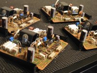
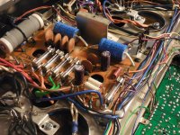
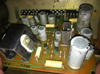
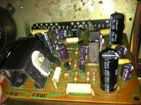
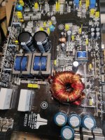
  3. They require amplifiers of high quality for the critical "first watt" of input power to achieve full potential
  4. They require careful placement of near-field objects and/or acoustic near-field treatments in room in order achieve their full imaging potential

"What is Different About Corner-Horn Imaging?"

Corner-horn imaging performance is a strong function of the room they're in, i.e.,

  1. The room's absolute and relative dimensions, its shape (including the ceiling), and the uniformity and relative smoothness of the walls next to the corner horns, i.e., the front and side walls near the speakers out to a distance of at least 4 feet (120 cm)
  2. The placement of the speakers within the room boundary (e.g., for a Klipschorn, the tailpiece-to-corner fit to seal the two mouths of the bass bins, or the length of the corner extensions from the bass bin on the front and side walls, and avoidance any intrusions into the room by bricks and other architectural details (yes, brick fireplaces and mantles can significantly affect imaging...) or canted low ceilings.
  3. The absence of near-field furniture or equipment that reflect acoustic energy, and
  4. The judicious use of acoustic treatments (...it usually doesn't take very much, but it usually takes some).
  5. The quality of the "first watt" of amplifier power driving them

post-16963-13819359279012.jpg


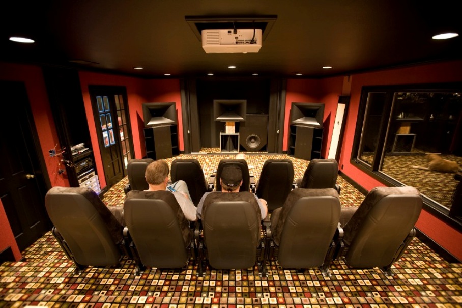
"How Do I Set Up Corner Horns to Increase Their Stereo Imaging Performance?"

One commonly heard complaint from corner horn users is that their speakers seem to have trouble achieving the same imaging performance as free-standing speakers. Loudspeakers of any type except dipole-radiators profit greatly in increased bass performance and much lower bass IMD of their speakers if they are placed in the corners of the room, toed-in to the listening position.

When many owners are polled about where they place their speakers in-room, invariably many answer "along a wall" or "a few feet from the front and side walls". Why would this occur? Paul Klipsch stated:

"The conclusion is pretty obvious. Whether you are using Klipschorn loudspeakers or speakers of some other make or type, you will get best stereo geometry and best tonality with corner placement of the flanking speakers (whether you use a center speaker or not) and the corner placement should be with the flanking speakers toed-in at 45 degrees." (Taken from Dope from Hope, Vol. 15, No.2)
There is something involving room acoustics and corner horns that is critically important to achieving excellent corner-horn imaging. The psychoacoustic effect that comes into play in this is a special case of the Precedence Effect of listeners called the Haas Effect, and the issue is early reflections of high mid-bass and midrange frequencies (i.e., about 250-4000 Hz) off the walls of the room closest to corner-horn midrange and high mid-bass horns.

From the co-inventor of the Klipsch Jubilee, Roy Delgado:

"Imaging and creating it by having two varying acoustic signals is an interesting undertaking. I have found that a smooth, unobtrusive boundary between the two speakers works very well with well-behaved and consistent polar patterns [of speakers]. The other thing that I have noticed that works well is no boundaries--like playing the speakers outside. Both do a very good to excellent job of accomplishing the imaging goal, but the caveat is that no boundaries forgives non-consistent polar patterns while a smooth boundary is a strict enforcer of consistent polar patterns. Pretty cool how that happens."
These early reflections should be controlled (i.e., a "Zero Reflection Zone" by P. D'Antonio) in order to achieve much greater imaging performance with speakers in the corners of their rooms.

What is the easiest way to control these early side and front wall reflections? Have a smooth boundary between the speakers (i.e., nothing between the speakers) and smooth front and side walls.

If this is not possible for your room and setup, the next easiest fix is to employ absorption panels. Many companies make fuzzy panels and acoustically absorbing tiles that can easily be placed along side walls and front walls of the your listening room. How much is needed? It turns out from the Haas Effect that controlling early reflections should be considered for 10-20 milliseconds of delayed reflections from side and front walls. This translates into about 11 to 22 feet (3.4-6.8 meters) of total path length at room temperature. However, the first 2-4 ms of early reflections are critical to control, translating to about 2-4 feet (0.6-1.2 m) of significantly reduced reflections. I use about 2 feet (0.6 meters) of absorption at the side-wall exit area of my corner-horn midrange horns.

Depending on your room geometry and listening position in relation to the corner horn placement (i.e., the included angle of the speakers relative to the listener--typically 90+ degrees included angle), the width of the midrange horn acoustic coverage laterally ( typically 60-100 degrees included angle), and assuming that your corner horn midrange horn controls its polar response down to its lower crossover frequency, the area that you should cover with absorption panels could be on the order of 2-10 feet along the front and side walls. I find that 2 feet of absorption along side walls works very well for Klipsch K-402 horns (i.e. Jubilee), and ~7 feet across the front wall, measured from the exit of each midrange horn's mouth.

Another approach is to place diffuser panels along the same near field areas but note that the use of diffusers in the Haas-effect areas will likely not achieve the same level of corner-horn imaging as the use of absorbers. The advantage of using diffusers is the relative liveness or deadness in smaller listening rooms.

If your listening position is more than 11 to 22 feet (3.4-6.8 meters) away, you probably have little work to do. However if you are like me and sit within 10 feet (3 meters) of your corner horns, you will find that the effect of using absorbent panels along the walls very much increases your stereo imaging performance.

"But What About the Equipment/Racks, Architectural Details, and Speaker(s) Between by Corner Horns?"

Again, the most straightforward way to deal with this is to simply remove all objects between the speakers, leaving a smooth wall. If this is not achievable, the alternatives are the same as above. I use absorption tiles on the side and top of my center loudspeaker, on the masonry, and a quilt-based cloth fabrics on other protruding objects like the mantlepiece to control early reflections.

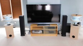
"But What About the Television Between My Speakers?"

This one is easy--place a temporary quilt, comforter, or acoustic absorption tiles in front of the screen when you listen in music only (i.e., no video) mode.

"But What About the Floor Next to My Speakers?"

Something as simple as a thin area carpet around each corner horn or even wall-to-wall carpet will suffice. This carpet does not need to be very thick or fuzzy to be effective.

"But What About the Ceiling?"

If your ceiling is relatively high, you probably don't have a problem. If it is lower than about 9 feet, and especially if you own Klipschorns or other horn-loaded loudspeaker having collapsing polar midrange horns, you should put absorbent material around the top/bottom mouth of the midrange horn or place diffusers/absorbers on the ceiling around your speaker's midrange horn mouth (especially if you sit relatively close to your corner horns). More on this subject later.

"What If the Amount of Absorption Recommended Above Just About Covers My (Small) Listening Room?"

Then you are probably one of those unfortunate corner-horn owners that would greatly benefit by placing your speakers in the corners of a larger room: in particular, Klipschorns require a large room to perform at their best . If perhaps you are using something like Klipsch Jubilees, then you can use them in a smaller room. More on the subject of midrange horns, below.

"Is All This Really Necessary?"

If you are trying to increase your corner-horn imaging performance: the answer is "yes" if you sit within 11 feet (3.4 meters) of your speakers. If you sit further back, then you will probably have far fewer imaging issues.

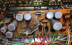
"What about Amplifiers and Corner-Horn Imaging Performance?"

In order to understand the effects of different type of amplifiers on corner-horn performance, you need to understand the effects of "early reflections", discussed, above, and the treatments available to recover your stereo imaging performance in rooms with cluttered areas between the speakers and non-smooth front and side walls. Once you understand the psychoacoustic effects on imaging of corner-horn speaker midrange horns/drivers, then a productive discussion on amplifier effects can occur.

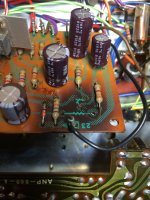
"What Are the Issues Related to Amplifiers and Corner Horns?"

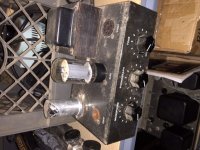
Amplifiers that exhibit high output impedance have the effect of providing a "reverb effect" in-room, especially if the room is small and relatively live acoustically. What kind of amplifiers have relatively high output impedance? Tube/valve-type amplifiers.

"Why is This an Issue...What is Happening?"

The reverb effect is due to strong room reflections back to the horns/drivers themselves, which are much more efficient than direct-radiator speakers at converting electrical energy into acoustic energy - and back again (...i.e., they are acting like microphones). Klipschorns, for example, convert about 10% or more of their input electrical energy into acoustic energy (according to Paul Klipsch's own calculations and measurements), while cone-type speakers typically are only 0.1% efficient or less. Planar speakers, like electrostatic and Magneplanar-like speakers, are even less efficient.

By the way, the same reverb effect happens with headphones in that sound reflections from the ear's closed-end tube reflect back to the driver, then back into the electrical domain by headphone driver-amplifier coupling. Special thanks to Bob Carver on identifying this phenomenon.

"So Why are We Talking About the Efficiency of Corner Horns and Imaging with Some Tube Amplifiers?"

Because the horns/drivers themselves are 100x more efficient at converting acoustic reflected energy back into electric energy to your amplifier's output terminals than direct radiator loudspeakers are, some of the room's reflected acoustic energy goes right back to the amplifier's output terminals.

"So What's the Issue with Amplifiers and Horn-Loaded Loudspeakers?"

Nothing, as long as the amplifier has low output impedance, a.k.a., high damping factor, like virtually all SS amplifiers and most higher-forward-gain tube amplifiers with feedback--such as multistage push-pull designs.

But if your amplifier has relatively high output impedance, that is, amplifiers with zero feedback, SET-type tube amplifiers, and particularly output-transformerless (OTL) types, what happens is that the amplifier output stage "feels" the reflected acoustic energy as an added load and the amplifier attempts to push back against midrange and bass bin driver diaphragms, albeit this effect is delayed in time from the original signal due to the reflected energy delays in-room. The net result is a reverb effect that is sensitive to SPL coming back to your corner horns from the room.

"So What's Wrong With That?"

Well, for starters, it's artificial and you can't turn it off unless switching to a lower output impedance amplifier, or switch to a much larger listening room with high ceilings. Paul Klipsch talked about measuring speakers with a "rubber yardstick" when you start to depart from a live music reproduction standard. [See also the article "Euphonic Distortion: Naughty but Nice".] That conversation is apropos here. If accurate reproduction is the standard by which Klipsch designed and built his speakers, then amplifiers with high-output-impedance used with very efficient corner horns in corners, where the reflected acoustic waves tend to have the highest amplitude and tends to pile up, will lead to distortion - non-harmonic distortion - the worst kind.

"So Why Do So Many Corner-Horn Owners Use Tube Electronics That Have High Output Impedance?"

I believe you can answer that question yourself now. Another way to achieve the same effect is to place a reverb unit in front of your amplifier input terminals - at least you can turn it off when you get tired of it.

"So What Other Issues Are There With SET Tube-Type Amplifiers?"

Low power SET-type tube amplifiers usually have too little amplifier power headroom--even for 105 dB/W-M corner horns thus leading to fast-transient soft clipping that some tube enthusiasts apparently like. Paul Klipsch's "rubber yardstick" comments are apropos here, too: it's preferable to not have any clipping effects at all if we are to retain an accurate sound reproduction yardstick. Also, SET amplifiers exhibit a much larger amount of harmonic distortion, that is, even harmonics. It is preferable to not have these harmonics added to our stereo's output since the magnitude of harmonic distortion is an indicator of the magnitude of amplitude modulation distortion (AMD) being generated, which is non-harmonic and very detrimental to the quality of sound reproduction.

An externally hosted image should be here but it was not working when we last tested it.
[/URL]

"Soft Clipping" of Tube Amplifiers that Masks Their Clipping Distortion but Introduces Harmonic Distortion

"So Why Do Class 'A' Tube-Type Amplifiers Sound So Good With Corner Horns?"

Multistage amplifiers, the type that is commonly used in SS amplifier designs (it's easy to get large amounts of amplifier gain) have more of something known as higher order harmonic distortion (which is synonymous with higher order harmonics) than do single stage or dual-stage amplifiers using little or no feedback.

Also the use of feedback to control these multiple cascaded amplifier stages tend to convert otherwise low-order harmonic distortions into higher order harmonics unless relatively large amounts of feedback are used.

But using large amounts of feedback negates the use of multistage amplifiers because it reduces the overall gain of the amplifiers in series. So typical SS push-pull, or even some class A amplifiers typically have much more higher-order harmonic distortion than do single- and dual-stage amplifiers running with no feedback.

Attachments

  • Khorn false corner.jpg
    Khorn false corner.jpg
    71.1 KB · Views: 380

Bottlehead 150V output transsformer winding

Hi I am currently working on bottleheaed headphone amp, but I am at the other side of the world, australia, shipping kills the cost in buying kit from U.S of A to the of last of A.
Therefore I could only resort in salavage parts from donation shop (slavo, vinnes), thrift shop and second electronic stores.

After study a bit more on the schematic and looking at other builders guide
https://www.headphonesty.com/2019/0...ck-headphone-amplifier-a-comprehensive-guide/

I saw that althogh their transformer secondary winding have dual 150V output but they just used 150V output for B+,and one 6.3V output for heating plate, corresponding to the scheamtic.

So I was wondering is there a Da vinci drawings trap that tricks other people no to copy their work (i.e you are suppose to have a parallel 150v winding connected) or just safely get a transformer that could provide 115v to 150v with rating of 10VA+ and another transformer for heating plate.

Also most of the transformer does have have 150v but only 115 to 120V,so how much performance degradtion will it casued if 120v is used instead.

Unusually sensitive hearing to presence frequency range?

Hello everyone! I've had this "quirk" for as long as I have memory, and I've always been extremely sensitive to the mid-treble and presence frequency range. My speakers and headphone measure good, but they all sound shrill to my ears especially when I raise the volume. I don't mean that kind of loud that blows your eardrums out, just the "sorta loud" most people usually listen music to.

I sort of hear a "ringing" sound like the one of a high-Q peaking filter at around 2,5kHz. This can't be the speakers or the room as I hear this on almost every system including headphones. The same systems also sound "fine" to other people.
I also have a problem going to concerts without earplugs. When things start to get too loud for me I sort of hear a "saturation" sound like the one from when you overdrive the amplifier, but it goes away as soon as I put the earplugs in so I know it's not the amplification. Again, I had friends with me who told me that they could hear just fine.

Usually, I counter this EQing out that range (from 2kHz to about 3.5kHz) by about -5 or -6dB which I realize is a lot! At that point I can raise the volume even more, so I'm not just compensating by making the signal quieter.

Besides that, my earing is good. I can hear to almost 19kHz which should be normal for a 22 year old. I don't suffer from tinnitus and a specialist checked my earing and said I'm fine!

Does anyone have such a sensitive earing as mine? Do you have any ideas about what could be the cause of it?

For sale Orfeusz 206

I have for sale a quite uncommon sound processor, called Orfeusz 206 by WAF Audio.

This processor is designed to make interactive spatial audio on loudspeakers. What this means is you plug in your sources, then with the mean of a joystick or a MIDI controller (or the mouse) you can control the incidence of the sources and create sound trajectories.
More info on the web: www.waf-audio.com.

Note: the processor can also make crossovers and parametric EQ, useful for prototyping your next loudspeaker diy project.

The processor is 3 years old, in a good condition, and I don't have much use for it now. It's located in Sydney Australia.
I'd like to have for it AUD 600, but will consider any genuine offer.

chaparK

McGohan MG-8 Mod suggestions?

Hi all,
I have a McGohan M8 single ended tube amp that I would like suggestions for recommended modifications to make it sound great as a guitar amplifier. Of course it’s a pretty simple circuit, not too far off from a tweed fender champ.

I have enclosed some photos of the amp and a schematic.

A couple of specific questions:
1. Should I eliminate the phono input?
2. If so could I use the phono volume pot for something else?
3. I plan to replace the filter caps and the connecting electrolytic caps, should I look at replacing anything else?
4. Should I consider changing the output tube from a 6l6 to a 6v6?

Thanks in advance for any assistance you can offer. I’m excited about this fun little project.

Justin

Attachments

  • McGohan M8 schematic.jpg
    McGohan M8 schematic.jpg
    771.7 KB · Views: 265
  • 7FEE7CA2-1B0C-47A6-BCC9-89E6759EDDBD.jpeg
    7FEE7CA2-1B0C-47A6-BCC9-89E6759EDDBD.jpeg
    99 KB · Views: 232
  • B899156B-07D0-4BFB-96C5-777A3D32940C.jpeg
    B899156B-07D0-4BFB-96C5-777A3D32940C.jpeg
    74.7 KB · Views: 200
  • 410EA44D-1B46-455C-903D-12F684F9B3D8.jpeg
    410EA44D-1B46-455C-903D-12F684F9B3D8.jpeg
    119.3 KB · Views: 233

Xsim and SineCap XO

In order to better understand what the individual parts do in an XO, I have started playing a little with Xsim. It gives really good insight even just with a dummy driver.

I tryed with a SineCap filter for a tweeter, i.e. a coil in parallel with the tweeter, without a capacitor in series.

I have made this simple filter where C1 is "short". But there is no response in Xsim. The frequence is just af line at default 70 dB. Xsim can't do that or am I doing something wrong.

1669125010361.png

Attachments

  • 1669124929869.png
    1669124929869.png
    2.8 KB · Views: 69

A/D/S 2000.1 mono amp

Good day bros, another amp that I have been working for some time an ADS 2000.1 mon amp, Initial problem was going to protect mode. I managed to repair by replacing gate resistors , FETs and drive chip on the power supply section. Now it powers up on blue light and with good rail voltages and no longer goes to protect mode. But the main issue was, blowing the output FETs at high side only whenever I replace a new one. Without FETS installed normally I don't see the gate drive signal on the high side but I get a good gate drive signal on the low side, with this I assumed that all output signals are fine but when I install new FETS the high side fets are getting shorted once I turn on the amp. Is it possible that the Drive chip IR2184S is not giving the correct high side gate signal even if it has a good low side gate drive signal? Note that shorted highside FETS are on the other bank only. Other banks are fine.
Projects by fanatics, for fanatics
Get answers and advice for everyone wanting to learn the art of audio.
Join the Community
507,786
Members
7,888,453
Messages

Filter

Forum Statistics

Threads
406,240
Messages
7,888,453
Members
507,786
Latest member
alexhmao