I've posted a small study comparing High, Medium and Low Frequency drivers in a variety of cabinets.
It's on another forum that allows me to edit/amend as more data becomes available.
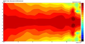
First up, some pretty colors:
Edit: Feb 2025- Speaker colours explained;
SPEAKER 3...
Normalised:
SPEAKER 3:
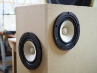
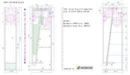
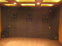
3 way speaker with twin 12” woofers in 13.75" wide, MT cabinet 9.5" wide with 6” midrange + 1” ring radiator offset from centre, no roundovers,
2.83V input applied:
Reference:


SPEAKER 2:
Normalised:
SPEAKER 2:
3-way speaker with 8” woofer in 21cm wide cabinet with 1" roundover, and 5”/1” coaxial driver,
2.83V input applied.
Reference:


Now, if you're not sure of how what these colors/shapes mean, then this directivity study is for you!
It's aimed at bringing you along the journey of speaker designs which have with smooth frequency responses in
many directions.
If you are familiar with seeing a single on-axis (or a few off-axis ) measurements for loudspeakers, please have a look at this study to observe how off-axis measurements varying over a larger span eg. up to
360° horizontally and vertically may add value to your designs, and how the use of
non-normalized polar maps may assist.
My study incorporates-
1.
High Frequency devices includes dome tweeters, ring radiators, ribbon tweeters, compression drivers, in cabinets with and without round-overs, with or without waveguides/horns, or even without cabinets (nude).
Start at the top for a background/explanation
Jump straight to posts for
non-normalised polar maps (horizontal
0 to +/- 90 ° minimum;
0 to +/- 180 ° horizontally and vertically where/when available):
All drivers highlighted in
bold type are by fellow DIYers who kindly offered their data for our perusal / interpretation.
A model of a
theoretical 3/4" flat piston tweeter on a 5 1/8" wide baffle with large 1.5" round-over
SB Acoustics SB19ST-C00-04 a 3/4" soft dome tweeter on a 5 1/8" wide baffle with 1" round-over
SB Acoustics SB29SDAC on a 8" wide baffle (coming soon)
Scan-Speak D2604/8330-00: 1" soft
dome on a 8.5" wide cabinet, offset 1/2" from center line
Scan-Speak R2604/8330-00: 1" ring
radiator in same cabinet, again offset 1/2" from center line
Fountek NeoCD3.0 a 8x60mm ribbon tweeter on a 8.75" wide cabinet with 10mm round-over courtesy
@DcibeL
Fountek NeoCD3.0 on a 11.5" wide cabinet with 3/4" round-over courtesy
Curt Campbell and
@jholtz
Fountek NeoCD3.5H a ribbon tweeter & integrated horn on a 8.5" wide cabinet with 3/4" round-over, courtesy
Göran @gornir
Fountek NeoCD3.5H nude (not mounted on any cabinet), courtesy
@Juhazi
B&W HF00963 in tapered tube hard dome tweeter in a minimal baffle/tapered cylinder, courtesy @
PKAudio
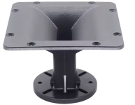
Tymphany DFM-2535R00-08 attached to a SB Acoustics H225 and H250 constant directivity horns, both nude
Tweeter of
SICA 5-5-C-15-CP coaxial driver, mounted in 7" circular frame with 1/2" round-over, courtesy
@vineethkumar01
Tweeter for
SB Acoustics SB17CAC / SB17NBAC coaxial prototype courtesy
@5th element
Tymphany XT25BG60-04 in Visaton WG148R waveguide, mounted on 11" wide baffle with 1.5" round-over
Various tweeters in courtesy
@augerpro's
waveguides mounted in real cabinets, with or without round-overs (including SB26CDC in 6.5" elliptical waveguide,
Peerless OT19NC00-04 in 8" elliptical waveguide, horizontal measurements),
Donate!
SB Acoustics SB26ADC in a
customized 8" waveguide for 60° beamwidth from 1K to 12KHz. courtesy
@fluid
tweeter from
KEF R series (non-META) coaxial, mounted in a cabinet with 1.5" round-overs
tweeter from
KEF Blade Meta/Reference Meta, mounted in cabinet with 1.5" round-overs vs no round-over
(awaiting cabinets)
2.
Medium Frequency devices includes cones and domes, typically covering 3-400Hz to 3-4KHz
B&W 5" FST midrange in 8.75" wide cabinet with r10mm round-over, courtesy
@DcibeL
Larger 6" FST midrange in
9.5" wide cabinet and
8.5" spheroidal cabinet
previous generation (Kevlar) 6" FST midrange in the same 8.5" spherical cabinet
Volt VM752 3" dome midrange in 14.5" wide cabinet, offset 1 11/16" from center, courtesy
@mbrennwa
Faital 4FE42 4" cone midrange in a 6" spheroidal cabinet
Purifi 5" and 6.5" drivers on same width baffle (completed, awaiting publication)
Purifi 6.5"
aluminium vs fibre cone
3.
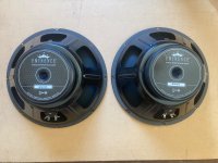
Low Frequency devices includes woofers and/or subwoofers, typically covering 3-400Hz and below:
KEF
LS60 's dual 5.25" woofers, side firing, in dual opposed configuration, rear ported courtesy
@bikinpunk
KEF
Blade 2 Meta's quad 6.5" woofers, in dual opposed configuration, 2 on each side panel, with rear firing ports courtesy
@bikinpunk
KEF
R11 Meta, quad 6.5" woofers, all 4 on front panel, with rear firing ports courtesy
www.audiosciencereview.com
Thanks again to all those involved who kindly supplied their measurements.
If you find anything that you feel is a misrepresentation of your data, please let me know.
All constructive comments welcome, as well as suggestions for better readability. It's a lot of graphs, I know.
PS. If a link is currently unavailable; then it is currently being updated/edited. Try again in 24 hours. Thanks for your patience.
Speaker 1...


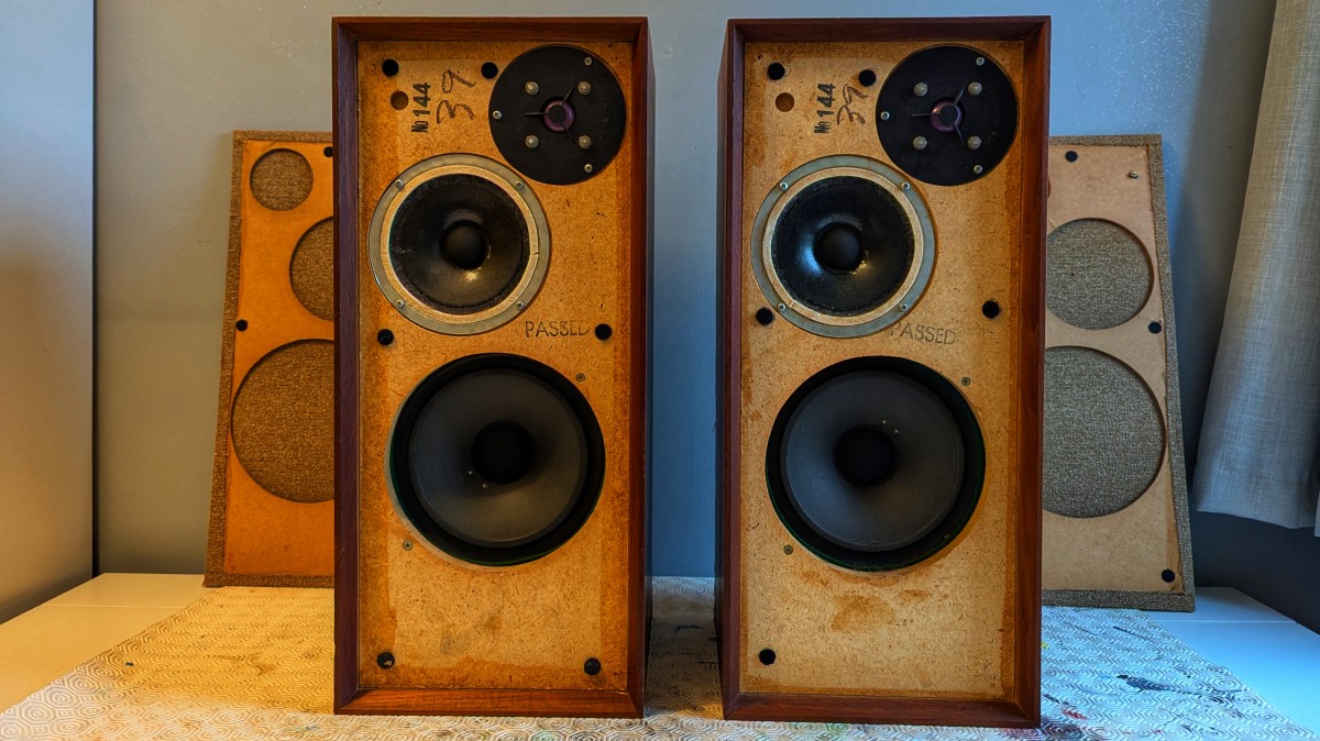
![PXL_20250325_202858459.RAW-01.MP.COVER[1].jpg](/community/data/attachments/1348/1348055-09583308872285fe6518e5759550b66f.jpg?hash=dWEA0eTIVL)


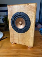


