Reamp + Isolator with Triad TY-250P

Hi, I need advices trying to achieve this Reamp-Isolator box. The impedance matching is still a mystery for me, particularly from the preamp to the soundcard.

REAMP:
Soundcard (RME UFX+) -> Line Output / Balanced / 75 Ohm
to
Preamp (Steavens The Brick) -> Instr/Guitar / Unbalanced / HiZ

ISOLATOR:
Preamp -> env. 5Vrms / Unbalanced / 10 kOhm
to
Soundcard (RME UFX+) -> Line Balanced 12 kOhm

For the reamp, I don't need to mimic Guitar impedance. I just use the preamp as insert overdrive/distortion in my DAW.

Here is the schematic:
Capture d’écran 2023-03-08 à 09.46.04.png

SD Card Player With AK4495SEQ, Balanced and Single-Ended Out $115 shipped in USA

I was a lover of SDTrans so I bought this to see how close it got. It doesn't get close to a tricked out 'trans but it has promise. Needs mods. Will include an SD card full of the well recorded shi-stuff vendors use at shows to make their systems sound good.

Attachments

  • 20230226_114213.JPG
    20230226_114213.JPG
    216 KB · Views: 105
  • 20230226_114225.JPG
    20230226_114225.JPG
    224.6 KB · Views: 99
  • 20230226_114315.JPG
    20230226_114315.JPG
    555.3 KB · Views: 73
  • 20230226_114437.JPG
    20230226_114437.JPG
    273.3 KB · Views: 110

Silver Flute W14 woofers

I did this planset in 2018 and very few know about them so i thot i should post the plans.

Not really subWoofers, but this is the best section to put them in.

This woofer is really cheap and a really decent performer, but difficult to get outside North America. If you need some bass help, in something small that sounds good this may be something of interest.

http://www.planet10-hifi.com/downloads/SF-W14-woofers-120218.pdf

This is the same woofer we use in Tysen V2.

dave
.

LM4562 Quality Issues (popcorn noise) - current situation in 2023

In the past, quality defects were found in the LM4562/LME49720 op amps.

See TI forum entry:
https://e2e.ti.com/support/audio-gr...um/415907/lm4562-lme49720-low-frequency-noise

The production of the early years should now be sold out.
Does anyone know what the current situation is? Has the production process been improved in the meantime? Is the new production good quality?

Dynaudio MSP200 woofer replacement?

Hey all!
I recently aquired a set of Dynaudio MSP 200's while roaming a second hand store. They looked questionable since the Woofers where swapped with a set of noname drivers with shot membranes but since the Cabinets and tweeters where flawless + price was irresistable i took them with me.
Now im trying to replace the Woofers with a worthy alternative. It would be nice to keep the looks original and use the original mounting holes, since the cabinets are in near mint condition.

-Since the cabinets are almost 40 years old i was wondering if it would be a good idea to change the capacitors of the crossovers too? If yes, are there any suggestions? PP, Elko? Specific Brands (Ideally with good availability in EU)?

-Is there a noticeable difference between a 24w100 and a 24w75? Spec wise they look quite similar. I would be able to aquire a set of 24w100 4 Ohm and possibly also 8ohm for a good price wich also leads to my next question:

-Lojzek mentioned the Volvo Dynaudio woofers as a possible replacement. For me they would be a neat replacement. The domes look similar, there are plenty around, the Price is reasonable and i think Lojzek mentioned the Mounting holes are also identical to the original 24w's. BUT they are all 4Ohm speakers. I was wondering if this would have a negative impact on the tweeters, crossover frequencys/ resistors or the general performance in any kind of way besides the higher load on the amp?

Looking forward to your Answers!

Schematic wanted for Creeks Phono-Stage "OBH-9" (MC only)

Is the schematic the same as those showing in post #12 under
https://www.diyaudio.com/community/threads/how-convert-creek-obh-8-to-mc-cartridges.151527/
with mentioned reducing of R12 ?

Thank you for an information.

Attachments

  • 3322973-2cc3eb46-creek-audio-obh-9-for-phono-preamp-for-mc-cartridge-modded.jpg
    3322973-2cc3eb46-creek-audio-obh-9-for-phono-preamp-for-mc-cartridge-modded.jpg
    55.4 KB · Views: 194
  • 3322974-69ae7aea-creek-audio-obh-9-for-phono-preamp-for-mc-cartridge-modded.jpg
    3322974-69ae7aea-creek-audio-obh-9-for-phono-preamp-for-mc-cartridge-modded.jpg
    67.2 KB · Views: 205
  • 3322977-b825869a-creek-audio-obh-9-for-phono-preamp-for-mc-cartridge-modded.jpg
    3322977-b825869a-creek-audio-obh-9-for-phono-preamp-for-mc-cartridge-modded.jpg
    64.3 KB · Views: 163
  • 3322976-a22a55fd-creek-audio-obh-9-for-phono-preamp-for-mc-cartridge-modded.jpg
    3322976-a22a55fd-creek-audio-obh-9-for-phono-preamp-for-mc-cartridge-modded.jpg
    51.2 KB · Views: 183
  • 3322975-1f272455-creek-audio-obh-9-for-phono-preamp-for-mc-cartridge-modded.jpg
    3322975-1f272455-creek-audio-obh-9-for-phono-preamp-for-mc-cartridge-modded.jpg
    70.3 KB · Views: 278

MCRU Update

Sorry we have been away for so long, as the UK's leading DIY mains cable supplier we now have over a dozen audiophile mains cables off the reel and a plethora of plugs and connectors for you to construct your own power cords. Please feel free to visit our new website at www.mcru.co.uk and mention diyAudio in the comments section when you order to be sent a free gift with your order.

Some of the brands of cables we stock off the reel.............

Belden - Acrolink - Furutech - Neotech - LAPP - Supra - Oyaide plus a huge selection of mains plugs and IEC connectors.

MCRU-No.-100-mains-lead-627x627.jpg

For Sale Soncoz LA-QXD1 Balanced DAC with aftermarket power supply and XLR/TRS cables (2 sets available)

Hi folks

I have two of these marvelous Soncoz LA-QXD1 DACs available for sale. each complete with a low-noise power supply and set of (2) 18" XLR/TRS balanced cables. I used them in conjunction with a miniDSP nanoDIGI 2x8 SPDIF processor (also available for sale) for a mind-bending budget active crossover 2+ way speaker set.

They are in perfect condition, work flawlessly, and have the original firmware 2021.
Asking $175 shipped for each set, buy both sets for $330, or $425 with the miniDSP nanoDIGI.

Located in the San Francisco Bay Area if you want to test/pickup locally.

Thanks!
Robert

Attachments

  • _VCL8466.JPG
    _VCL8466.JPG
    143.7 KB · Views: 47
  • _VCL8475.JPG
    _VCL8475.JPG
    187 KB · Views: 40
  • _VCL8468.JPG
    _VCL8468.JPG
    123.4 KB · Views: 51
  • _VCL8471.JPG
    _VCL8471.JPG
    119.2 KB · Views: 55
  • _VCL8472.JPG
    _VCL8472.JPG
    131.3 KB · Views: 41
  • _VCL8473.JPG
    _VCL8473.JPG
    120.3 KB · Views: 40
  • _VCL8476.JPG
    _VCL8476.JPG
    196.4 KB · Views: 42

New transistors (& resistors?) for 70s Ampeg amp?

In the barn find of the day, picked up this Ampeg guitar amp. Was making a loud hum. Opened it up and found this exploded capacitor, which is nice to see, because you know the problem is going to be solved in two minutes and you don't have to hunt for it.

IMG_20230220_172624.jpg


IMG_20230220_172511.jpg

IMG_20230220_172520.jpg


Looking at the amp, I wondered whether it would benefit from more modern transistors? I got this feedback about an Akai tape machine not long ago. It looks like it has BC169B, 2N4062 and 40623, 40625 transistors.

Helpfully, Ampeg glued the schematic to the bottom of the chassis, and labels everything on the circuit board -- gotta love that.

Relatedly, the hiss is very pronounced with volume and treble up. It does have carbon comp resistors, lots of them. Where would be a good place to start to reduce hiss? Resistors that go to ground? Others have said this amp is quiet when in good condition. Like my solid-state Fender, the reverb hums a lot.

Any feedback welcome. Here's the schematic.

IMG_20230220_173135.jpg

Attachments

Help with repairing a SAE 2600

It is a very recent version (I think 1980), it has the toroidal transformer, 2 rectifier bridges and the modification on the protection board to eliminate the delay on the relay when switching off)

The flaw is that by setting the input sensitivity to -3 and 0 dB on any of the 2 channels you can hear a loud buzz in the speakers, the vu meters go beyond half scale and the final transistors heat up a lot.
By measuring the DC output it rises to 100/120 mV.
With the input sensitivity of - 12 or - 6 dB it works great and there is no abnormal heating.
The amplifier has all original toshiba transistors and the drivers are plastic, everything looks original, never been repaired.
The amplifier is set to 240V and feeding it to 220V (standard voltage in Italy) the power supply supplies approx. + 80 / -80V.
Connecting the input signal on one channel at a time everything works fine

I saw from the wiring diagram that the power supply should deliver +/- 105 V, do you think this could be the cause of the problem or do you have any idea what could be the cause of the failure?

Unfortunately I did not find the service manual on the net but only a wiring diagram, can you help me?
Many thanks to those who want to help me.
Massimo

Attachments

  • IMG20220505122935.jpg
    IMG20220505122935.jpg
    457.5 KB · Views: 797
  • IMG20220505163123.jpg
    IMG20220505163123.jpg
    533.8 KB · Views: 712

What cartridge upgrade from a Shure V15 V-MR?

I am considering trying a different cartridge. Maybe a MC. There is nothing wrong with the sound from this Shure MM.
Its just I don't know what more I might be missing.

If I moved to a MC I would also need a step up transformer.

The Shure has been highly regarded over the years, but would a change be a notable upgrade?

Budget, I suppose what it would take for a clear step up.

Linn LP12
I forget the model but I updated to their own light weight carbon arm a fews ago.
Ext. Psu

Yarqin Lesbox tube phono amp
Cary SPL50a preamp (upgraded)
Beard P50 tube amp (upgraded)
Rogers J149 speakers (just love the vocal ability of these) + 2 x b&w subs tuned to support.

X-10D Buffer Clone Query (PRT-09A)

Hi,

First post on here, little to no electronics experience, but desperate times...fingers crossed...

After loving an old Musical Fidelity X-10D tube buffer, I have had a very knowledgeable friend put together one of the cheaply and widely available Musical Fidelity X-10D PCB clones for me.

The specific one being used is described as the PRT-09A and supposedly has an upgraded power supply along with a couple of other supposed 'upgrades' compared with the original board.

Board has all been built-up using mundorf evo caps etc and according to my friend, it all tests fine, but there is an audible hiss coming through the speakers when connected. Pretty loud too.

Guy from China who sold me the board has been helpful to be fair. AC input is set at 30 0 30, so he initially suggested lowering the test point voltage down (initially set at +36V, lowered to 28VDC), but no change.

GND is properly connected to chassis and the hiss is present with the board out of the chassis anyway, so not that either.

All resistors testing correctly.

Has anyone ever used one of these X-10D clone boards before and if so, do you have any ideas as to what the problem might be?

Appreciate the first thing someone will say is it's my own fault for getting a cheap PCB from China and you are probably right, but given the seller has come back, it seems to suggest he has faith in the board. Maybe.

Any suggestions greatly appreciated (chuck it in the bin?).

NB. All technical discussion will have to be relayed back to the guy doing it for me as my electronics knowledge is pretty embarrassing. He's not in for forums, so I said I'd post something.

Many thanks in advance.

P.S. been reading stuff on this site for years and whilst most of the discussion makes no sense to me at all, it is a fabulous resource, so keep up the good work folks!

Seeking input on ScanSpeak 3-way

A few years back I bought a set of drivers and the time has come to make something out of them. I have started to model the crossovers and wanted to hear if you think I might be on the right track.

Elements:

Enclosure-wise, I am thinking that a 60 liter bass reflex box for the woofers and a closed enclosure for the midrange, something similar to Troels Gravesens Ekta Grande might be reasonable as a first trial box.

This is just an early sketch, so it is based on traced SPL and impedance curves from Scan Speak. Break-in and TS-measurements are under way. The crossover is modelled without a box and assuming all drivers are mounted with aligned acoustic centers.

I have attempted to integrate a baffle step around 500Hz and I have tried to keep the impedance above 3 Ohms.

What are your thoughts on this - on the right track here?

Another question, do you think it will be possible to drive mid+tweeter with a tube amp with this kind of impedance?

Attachments

  • Impedance.png
    Impedance.png
    7.4 KB · Views: 355
  • Filter.png
    Filter.png
    9.5 KB · Views: 253
  • GD_and_Phase.png
    GD_and_Phase.png
    31 KB · Views: 245
  • Directivity_hor.png
    Directivity_hor.png
    10.5 KB · Views: 222
  • Power_and_DI.png
    Power_and_DI.png
    12.1 KB · Views: 265
  • SPL.png
    SPL.png
    13.4 KB · Views: 362
  • XO-schema.png
    XO-schema.png
    11 KB · Views: 789

Need synthesizer schematic Behringer mod D

Not sure this is the right forum, but giving it a try here. Looking for a schematic or service manual for a Behringer Model D synthesizer. Below is a photo of the ID info. Already have the users manual. Apparently most of it works, but the main output and headphone out are dead. Trying to help out a freind via long distance communication.

Thanks in advance.
77ED3162-1BCF-4392-8DD4-2647131A573C.jpeg

Clone JP200 oscillation

Bonjour,
J'ai un clone JP200 et j'ai remarqué en sortie une oscillation amortie à très basse fréquence au moment de la mise sous tension. (0.1Hz)
Si on branche la sortie sur un ampli qui passe le continu ou sur un ampli qui descend bas en fréquence j'imagine qu'il ne vont pas aimer.
Avez vous remarqué le même phénomène que moi ?

Merci par avance pour votre aide
Cordialement

Attachments

  • 20230304_113222.jpg
    20230304_113222.jpg
    453.1 KB · Views: 83
  • 20230304_113245.jpg
    20230304_113245.jpg
    548.1 KB · Views: 94

Electrocompaniet EC25 two channel audio ampilfier Transformer

Hi All,
I've just had the primary winding in the transformer for this amp go u/s, no continuity, through white and green wires. Has anyone successfully transplanted a suitable replacement transformer and if you could you let me know what you used? Other then that has anyone has transformers rebuilt and if so any suggestions who might be able to do one like this one:
Transformer 2.jpg

Many Thanks in advance,
Joe

Electrical Stove Dual Simmerstat Replacement

G'day Guys,

I need to replace a dual simmerstat on a Fisher and Paykel Stovetop.

That part is relatively simple.

The hard bit is that the faulty simmerstat has taken a wire with it.

20221225_113727.jpg20221225_113743.jpg20221225_113712.jpg

As can be seen from the photos: The white wire is burnt out and will need to be replaced with the simmerstat.
However there are markings on any section of the white wire to speak of. No temp rating, gauge or voltage.

Voltage and temp rating aren't too hard - as high as possible something like 200 degree 600v would probably be ideal.
The wire gauge is what is stumping me.

Does anybody have any experience with such things that may offer a suggestion.

The simmerstat is a Robertshaw MPD-110 rated at 15A

Ordering parts

I don’t know about you guys but ordering parts is my least favorite thing about this hobby. Mouser and digikey are my go to places but their systems make it difficult. I can create a list on their websites but generating it accurately takes me way too long. I’m doing all this on my iPhone (11) using cellular data. I don’t have access to the Internet via wifi which may be the biggest issue. Please advise me how best to handle this
Thanks

Class D Speaker Output Relay?

Hey all, so the 4 relays on an Orion HCCA 8000.1D are not switching on after amp boots up, everything else is confirmed working/switching properly, and I see my 50Hz input signal just before relays, so while trying to figure out what is going on I realized I do not even tech I ally know what the relays are exactly for and/or what conditions must be met for the relays to a switch on. I have seen relay failure before but all 4 at once?

If anyone can help shine some light as to what the Speaker Output Relays are for, the conditions needing to be met for switch on, and other other pertinent info would be greatly appreciated. Ty 🖖🏼

Attachments

  • 21493C35-D6CA-4A38-A058-71144CE5E564.jpeg
    21493C35-D6CA-4A38-A058-71144CE5E564.jpeg
    653.4 KB · Views: 164

Please help explaining this XO circuit

I draw this xo circuit from a 15 yr-old Vocopro Karaoke speaker. There are no markings on the inductor or the mylar caps.
I don't understand why the 8 Ohm tweeters are connected in series. Should I replace them with 2 4-Ohm tweeters.
And what is the purpose of the resistors & mylar caps in series?
I'm replacing the 4.7uF cap and re-wiring it with 14 gauge stranded copper. Thanks in advance.
vocopro_speaker_xo_edited.jpeg

Marantz CD 84 help

Hello
I have a marantz cd 84 cd player with a problematic DAC (Decoding) condition so it doesn't output audio. All button functions when playing, pause, FF , REW, Back and others on the display look normal. I have also checked all the JRC 4560 ICs for CD Out and Head Phone out, all are normal. The "mute" and "Kill" sections are also normal. Is there a father who is a digital audio expert who knows about this problem?
I once made a VCD Player using the Mpeg VCD kit by utilizing the Marantz CD-84 CD Player's EFM (RF) signal output and it worked.
Now I want to try to modify the normal EFM (RF) signal output that was converted to an external DAC but I don't know how.
Any digital audio experts know how to modify it
I look forward to a response from you guys here
Thank You.

For Sale Peavey LowRider 18 PAIR

I'm asking $50 each (two available) with local pickup in southern Michigan (Lansing area).

I have the original packaging, which consists only of the cardboard wrap from Peavey and shipping them is very dicey so I would prefer local pickup

I purchased these Peavey Low Rider 18 subs as new units, one at a time a couple of years apart, but have never used them. They seem to have slightly different construction: one has a straight sided basket and the other curved. I think Peavey updated the design but kept the same specs. Both drivers are in good shape as you would expect for the lack of any use and only storage in the original packaging. These would work well in an OB system.

Please PM me or post in this thread if you are interested in buying them.

Specs and price here:
https://www.parts-express.com/Peavey-18-Low-Rider-Subwoofer-Speaker-Driver-294-301

Boss AD-3 protects hifi-speakers?

Hi good folks.

I would like to give my friend a preamp for his semi-acoustic so he can add some chorus etc. playing through his stereo. Speakers are low priced HiFi so must be protected from the peaks of strumming. Found a Boss AD-5 for cheaps and it has all he could dream of, but Im just worried of his speakers. I have PA drivers lying around, but no time to build pretty speakers for his livingroom 😊
Cheers!

Pete Millett 6P1 Buffer

The board is done minus the Nutube, will be using the isolation mounting system, but it looks fiddly and fragile, and my hands, eyes, and patience were diminishing, so enough for today. It will be powered by a positive Ultrbib and connected to a Maya R2R volume control and input selector. Have to get a chassis and mount and wire everything, that will be the hard part!

Attachments

  • 20230306_142524.jpg
    20230306_142524.jpg
    391.8 KB · Views: 86
  • 20230304_140354(1).jpg
    20230304_140354(1).jpg
    395.7 KB · Views: 85
  • 20230304_130143.jpg
    20230304_130143.jpg
    382.8 KB · Views: 84

Home Etched PCB Parallel OPA1688/1656 Headphone Amp - you can do it too

Here is a blast from the past. I designed this headphone amp years ago and just remembered how good it sounds and how easy it was to build. It’s a great project for anyone wanting to try etching their own PCBs. I used to do this all the time with laser printer toner transfers and HCl+H2O2 (muriatic acid and hydrogen peroxide).

This amp uses the OPA1688 opamp to drive 2x parallel OPA1688’s. This helps boost the output current. This was before the OPA1656 was available and I think changing to the latter will improve the output power. JPS64 did the home etch layout for me at the request of member Dibya - who I think also made this. Anyhow, kudos to JPS64 for a great layout and his generosity.

Here is the schematic:
B23F55FD-0175-4BBC-A948-E0D8D6D8D686.png

Here is the home etch layout:
AC108CE6-13A6-42DA-9746-2CDB088A75DE.png

Built up:
D723E28F-B833-46CA-B26D-2DEAFE3105E3.jpeg

Topside:
8869F733-133D-4985-9DAB-8D1C86E74A32.jpeg

Assembled into chassis with an ultra low noise DCDC PSU (also home etched):
8DCDB10F-7D44-4D02-8B61-5D3B6F76B1CE.jpeg

If you guys are interested in a real PCB, I’ll ask JPS64 to generate the Gerbers. But the point of this thread is to get folks to try the home etching method. I can explain more later but basically you make a laser print of the above layout on paper. Take that and iron it onto a blank copper faced PCB stock. The toner acts as acid resist. Then etch with acid peroxide solution and then drill holes if needed. This is why surface mount is nice - no drilling needed as the drill bits are very small and break easily with slightest side pressure. So a small Dremel drill press is a must.

It sounds great by the way. One of the easier home etched amps.

It was one of the nicest sounding amps in my collection at the time.
38FC0BD4-1484-4787-8BE4-D134703D5D72.jpeg

DSP making a 2.0 with mono low bass and stereo higher frequencies.

Hi, i was wondering if someone have some DSP knowledge? I have 2 speakers in the same enclosure for a portable speaker and was thinking maybe i can make it stereo. This can be done easely but if one channel put out bass and the other channel nothing , it will act as a passive radiator( the speaker with no signal ). So i was thinking could i filter out the bass and make it mono while playing the higher frequencies as stereo integrated in 1 channel.

Thanks!

Replacement woofer for a BG subwoofer?

What is the best method to reverse engineer a woofer to a subwoofer enclosure. I am working on a subwoofer for my SIL. It is a 10" Bohlender Graebener Z sub. The voice coil rubs, and the cone has disconnected from the VC. My choices are; Try to find used replacement sub or driver. Have the driver repaired. Find a new compatible/equivalent replacement to fit the enclosure. I am thinking the 3rd option would be the easiest to source once I determine the requirements. The dimensions of the interior of the cabinet are;

14-3/4" Deep x 15-3/4" High x 11" Wide. It has a ~3-3/8" diameter x 9" long port.

Interior volume is taken up by a brace, the woofer, the amplifier & the port. The gross volume is ~1.4 cubic feet. After subtracting the brace, woofer amp & port the interior volume is ~.75 cubic feet.

Since I don't know the impedance of the woofer, I will go out on a limb and say it is 4 ohms. The amplifier looks A/B and pretty beefy based on the transformer.

BTW the woofer has what may be a part# (10P32) and date code (20030430D) if anyone can tell by this where to find a replacement. It has a stamped steel basket and a vented pole piece.

2-way with Oberton 6B150 and Faital 1440

Im planning to build a speaker with Oberton 6B150, Faital 1440 and RCF HF950. Is this a stupid idea?

I cant find any information on the 6B150 here in diyaudio, is it a bad 6,5"?
I want to keep the speaker pretty small so thats why im consider the 6B150.

6B150:
https://en.toutlehautparleur.com/oberton-6b150-speaker-8-ohm-6-5-inch.html

HF950:
https://en.toutlehautparleur.com/horn-rcf-hf950-90x50o-throat-1-4-inch-front-11-81-x-11-81-inch.html

HF 1440:
https://en.toutlehautparleur.com/compression-driver-faitalpro-hf1440-8-ohm-1-4-inch.html

Sorry for my bad English..

//B

JL 500/1 - Broken pad during cap replacement, Advice needed

Hello,

While replacing one of the caps on my JL 500/1, I messed up and lifted the pad on the top of the board. The pad on the bottom is fine.
I hope the top pad was just there for structural integrity and using the bottom pad alone will be suffice.
Is this an issue and if so... how would I go about fixing it properly?

Any help is greatly appreciated.

Top

PCB Top.jpg


Bottom

PCB Bottom.jpg

Scheu Bearing and Platter, DIY Base, DC Motor

$650+ exact shipping cost. Moving overseas and selling everthing. Figured I'd list it here before putting it on eBay. This is a Scheu bearing and 40mm platter mated to diy cocobolo and 360 brass base. The bearing is a known commodity, tight tolerance inverted style made famous by Scheu. The base was based on a Scheu table I owned that used steel rods threaded through acrylic. This cocobolo and brass version is heavier and sounds much better. Weighs about 17.5lbs. The table this was based on, The Eurokit 2001 was reviewed well by Art Dudley in Listener.

The fit and finish has some diy quirks (see pics) and the threaded inserts stick out a bit. There is a chip that can be seen in the pic. I had it on three Stillpoints Ultras (not included) and the sound was excellent. The hole is cut for a Rega, but the distance between the arm board and the top of platter is 52mm, so you need to make up the distance. Origin Live sells a sliding VTA adjuster for Rega arms that does that perfectly. I had it that way on the other deck and I kept it on this one so that I could experiment with different arms by making simple discs and mounting them to the base. The pivot to spindle distance is variable by moving the arm pod on the brass sliders. Butcher block not included.

The motor pod is from Scheu and is DC, platter driven with thread for isolation. Scheu currently sells a table called the Cello Classic for $3899 that uses this bearing and a thinner, 30mm version of the same platter. Weight is roughly the same. This table hangs with the modern Scheu lineup sonically. Same bearing.

Attachments

  • 20230226_130700.JPG
    20230226_130700.JPG
    390.6 KB · Views: 141
  • 20230226_130831.JPG
    20230226_130831.JPG
    268.9 KB · Views: 127
  • 20230226_131623.JPG
    20230226_131623.JPG
    568.3 KB · Views: 137
  • 20230226_131706.JPG
    20230226_131706.JPG
    480.5 KB · Views: 139
  • 20230226_131714.JPG
    20230226_131714.JPG
    319.7 KB · Views: 132
  • 20230226_131724.JPG
    20230226_131724.JPG
    329.7 KB · Views: 129
  • 20230226_131730.JPG
    20230226_131730.JPG
    355.3 KB · Views: 140
  • 20230226_131741.JPG
    20230226_131741.JPG
    325.2 KB · Views: 125
  • 20230226_131754.JPG
    20230226_131754.JPG
    180.9 KB · Views: 126
  • 20230226_131759.JPG
    20230226_131759.JPG
    226.7 KB · Views: 125
  • 20230226_131810.JPG
    20230226_131810.JPG
    279.6 KB · Views: 111
  • 20230226_142140.JPG
    20230226_142140.JPG
    269.6 KB · Views: 125

FS: PAIR of JBL/Selenium 18" Woofer 18WS600 - great for large format OB

These drivers are NOS, never used, in the original MFG packaging. I bought them several years ago when I was planning to build a large format open baffle loudspeaker a la the John Busch Widowmaker. They could also be used as the upper driver in a design similar to the Pure Audio Project Trio 15.

This driver has very smooth response up to 2kHz and could be operated in a wide band down to 60Hz. It offers relatively low distortion for a large format PA driver. I unfortunately never got around to building the project and since then my loudspeaker efforts have gone in a different direction, so it's time to find these a new home.

You can find the MFG datasheet here:
https://jblpro.com/en-US/site_elements/18ws600-spec-sheet

Retail is about $200 EACH. Asking $150 plus shipping for the PAIR via PayPal. Local pickup is always welcome in the Lansing Michigan area.

Strain Gauge Pick Up System- Panasonic EPS-451QD with Precision Fidelity Demodulator

Newbie here in Atlanta. Greetings to all of you!
I bought this pick system when I was in grad school and have used it sporadically, last time about 15 years ago. I have 2 OEM replacement styli.
I am interested in getting feedback strain gauge owners/users (as opposed to 'I've heard that... comments) on the Precision Fidelity (PF) Demodulator- are there upgrades available (caps are original and likely dried out) as well as the Panasonic pick up.
Curious if any of you own, have worked with, heard or seen the PF version.
1. What do owners of this pick up system say about reproduction quality?
3. What is the longevity of the actual cartridge (EPS-451QD)?
4. Finally, does anyone known the 'compliance 'rating of this stylus/cantilever- low, medium or high compliance? I will be taking it off a LINN Basik LVX arm and mounting it on an ET2 linear tracking air bearing tonearm.
Thanks in advance for any real world info you can share.

OldSkool Bob

EPS-451QD family resemblance.pngPF Demod 1.jpgPF Demod 2.jpg

aligning the voice coils and/or sloping the baffle back time aligns automatically?

The first is yeah moving say the tweeter physically back so its voice coil is above the woofers', or moving a horn backward or forward for the same effect. The second is where the baffle is sloped/angled back to essentially align the voice coils to the listening axis while keeping the front baffle flat without steps.

I feel skeptical these ideas can really work automatically and sufficiently, since they ignores the actual driver time response and the effects of the crossovers. But it's not an area I worked in a lot since by the time my career progressed to where I had tools to measure such I was in autosound where that was the least of my worries.

By the way here "time alignment" means the initial arrival sound from each drivers come at the same time. I do NOT mean "phase" at all, that's a different headache...

Explendid amplifier designed by Michael Bittner, our MikeB

MikeB, our forum friend, is 30 years old Computer Programer, owner of the Synetic Software.

As he is working very hard those days, having small time to sleep, he asked me to publish his amplifier, result of some monthes of research, where i could cooperate with my ears with the valuable help of Mr. John Mateus from Fredon - New Jersey - USA the one that constructed, evaluate and helped a lot including his enormous professional experience in audio reinforcing our evaluations.

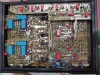
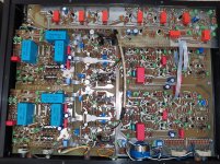
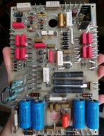
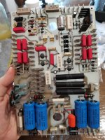
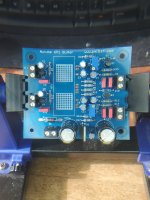
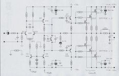
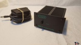
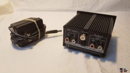
His amplifier is called Symasym, that is Symetrical Assymetrical, a very good design, the one i use to listen, together with GEM, AKSA and JLH...i apreciate, very much, all of them, and cannot stay without those units..in my idea, the best i could find using BGTs.

Alike many others, that use 36 or 37V simetrical supply, it produces 50 watts RMS minimum over 8 ohms and go to 100 watts over 4 ohms, naturally.

Long research was made, many comparisons where made, that had Hugh Dean cooperation, also Graham Maynard cooperation and some others that are not in our diy audio forum.

Professional audio recordings were made and E-mailed in 10 to 20 Megabytes size, using Wave and MP3, with comparisons made using reference amplifiers, in this case, a very expensive Yamaha Home Theater, the JLH basic and first design, and one Harman and Kardon.
Audio was generated by sinthetizers and Graham Maynard sent a beautifull CD, the one you can perceive very deep low humble from pickup and turntable, we could see woofer moving 5 hertz.

Recordings was made using Professional Senheiser Microfone... 1 meter distanced from speaker.... sound recorded was a DAT recorder and them copied to the computer audio board, converted to MP3 and also mailed as Wave.

The amplifier is very good...try it.

Very good audio reproduction is guaranteed

regards,

Carlos

Attachments

  • symasym4.gif
    symasym4.gif
    13.3 KB · Views: 53,274

ESP P99 Subsonic Filter Issue - Faulty Op Amp?

Hi All - I've just finished assembling a phono stage pre-amp project based on Rod Elliot's P06 phono stage, P05C power supply, and P99 subsonic filter. I was testing the completed modules yesterday using the instructions given by Rod's website and found that the P99 subsonic filter seems to have issues.

I have used LM4562 op-amps in the P06 module and OPA2134 in the sub-sonic filter. P05C and P06 appears to be functioning correctly.

Testing routine was to connect the module using 100R 1-watt safety resistors in series with the +ve/-ve supply, then measure the voltage at the output pins of the op-amps (pins 1 and 7). With power applied, apparently the DC at the output pins should read no more than a few mV - perhaps even 0mV - for both op-amps. I am using a multi-meter for testing, and using the P05C power supply which is running off a 15-0-15 toroidal transformer, regulated to 15v output (reads at a steady +14.97v / -15.11V)

For the P99 subsonic filter, I am getting very different readings between different pins on each op amp. Some pins are 10s of mV, others are over 100mV. I have checked the following:
  • All electros are correctly oriented.
  • All resistors values are correct.
  • Continuity tested the supply rails to the op-amps, seems fine.
  • Check all solder joints for bridging / dry joints etc, again, seems ok.


  • When assembling I checked all component values with the meter and picked components that were closely equal values, so all components were checked with the meter prior to assembly.
  • I have visually inspected the board and I cannot see any breaks to the traces or visible damage.
I am a bit stumped now - so far I was not able to see anything obviously wrong, I don't want to plug it in and try it since it has not passed the testing procedure.

I am wondering if one or both of the op-amps is faulty, or if there are other things I should be checking to try and rule out issues? My testing kit is a UNI-T UT-89XD multi-meter. Any suggestions and recommendations would be very well received.


IMG_0339.jpg


:cop: Edited by moderation to remove reported image

OT winding data for pair of 807 tubes, does this look right?

Ive been playing around with OPT_da to come up with the specs for winding an OT for a pair of 807 tubes running in UL in class AB1.
I have been reading the guide after translation, but feel I have some variables wrong.

Firstly, i am after the primary plate resistance (Rp) the datasheet for 807 only shows load resistance, so I just went with 40K as used on a pair of 6L6.
Im not sure how much this differs with an 807, but it must be close.

I am also not too sure on what core size to select for a given wattage, and i may have this wrong what ive selected, but i went with EI78 as i feel that looks the right size for other transformers ive seen rated at similar power.
The other thing I dont see in this software is how many layers thick of laminations that I need stacked.
Anyway, I have the majority of lamination sizes available along with copper wire.
Personally, i get the feeling that the number of turns on the primary is overly high, but i could be wrong.
See chart below.
TIA 🙂
OPT.png

Power amp under development

This is a schematic of my latest amp. It is a quasi-complimentary design running mosfet outputs.

The prototype running on my bench with the rails noted delivers around 200 watts into 8 ohms. The amp is very quiet and seems to be very low in distortion (I have trouble measuring below 0.1%).

With the right power supply and FETS it could deliver maybe around 800 watts or more into 2 ohms. The protype is running IXYS26N50 FETS and 4 or 5 of these per rail would be up to it.

The one planned for my Hi-Fi will run IRFP450's. These seem to be more linear and approach clipping better.

Want more power - add more FETS (and power supply)

Anyway feedback and ideas are welcome.

Cheers

Attachments

  • nmosamp2.jpg
    nmosamp2.jpg
    70.4 KB · Views: 55,075

Pioneer A-8600X Stereo Amplifier Schematic request

Dears,
I have Pioneer A-8600X Stereo Amplifier with speaker relay switching issue.
Please refer to the attached images.
I have tried to find the schematics of the Amp but no luck so far.:sad:

Can you please help me to find the schematics of Pioneer A-8600X ?

Thanks In Advance.

Attachments

  • P1.jpeg
    P1.jpeg
    69.8 KB · Views: 233
  • P2.jpeg
    P2.jpeg
    279.2 KB · Views: 350
  • P3.jpeg
    P3.jpeg
    102.5 KB · Views: 217

Pioneer PD 73: dead after RF / T.Err short-circuit?

Hi all, I'm new in the forum and I need some help from somebody with experience on Vintage Pioneer CD players

I was recalibrating a Pioneer PD 73 that was always creating troubles with skipping CD when I, by mistake, shortcircuited Pin 1 (RF) and Pin 2 (T.Err) of TP1. The device was in test mode when the shortcircuit took place. Suddenly the device display turned off as well as the power led indicating operating conditions. Trying to turn off and on again the device didn't helped nor anything else. Basically I now have a nice black shiny BRICK!!!!😢

This already happened a month ago on a Pioneer PD 7300, but given the lower value of that device I didn't spend too much time troubleshooting it. With PD 73 situation is pretty different since I really don't want to throw such an amazing piece of hardware to the bin.

Anyone that experienced something similar in the past or that can help on troubleshooting?
Many thanks, Riccardo

Attachments

Recommended software for designing amplifiers

I'm a newcomer learning about amplifier circuits. I'm mainly interested in putting together simple valve amplifiers to begin with.

I am getting my head around it slowly, watching a lot of videos on YouTube, uncledoug's being the most useful. I've got a good understanding of the basics. I'm looking for some software that would help me not only build schematics, but also show the voltages and resistance in the various parts of the circuit. I think this would be a useful tool for learning. To be able to see how things work and tweak and play around with a circuit would be great. I know there are plenty of products which do this, I'm looking for recommendations for a beginner.

I've got some combined triode/pentode valves and pretty much everything else I need to make a start with a simple, single ended amp. I've had these bits for a while but a lack of time has stopped me getting on with it. I'm really looking forward to getting started.
There are plenty of circuits I can follow online but I think building a circuit in software first would help reinforce my understanding.

Question on directivity index and amplitude

So I've searched all around and couldnt find an answer to this question: Does directivity decrease or increase with amplitude?

In other words, say you're using a 1st order crossover at 1038hz with a 15" driver with an sd of 855cm. Thats a piston diameter of 13" roughly,
or a Q of 10 at 1038hz. Being that its amplitude down 9db at 2076hz, does the directivity decrease with increasing frequency or stay the same?

Recovery Mark Levinson 26 and Mark Levinson 27.5

Hello everyone I want to tell you about the maintenance of Mark levinson 26 & Mark Levinson 27.5.
First I bought an amp and used it as a pre-amp for the Cantata music centre.
The sound was good, but lacked depth and volume. So I bought a Mark levinson 26. the Sound was amazing, I couldn't believe my ears! But one channel rustled in the silence. Since it is already 30 years old, I decided to remove the lid and see what condition it is in. The former owner replaced most of the capacitors.
I also noticed that the four resistors were very hot cracked and burned.
I ordered new original dale 1w 20om 1% and raised them from the Board by 5mm, the temperature dropped to 70c. I also ordered the new expensive original sprague 672; nichicon muse kz. the Sound is even deeper and richer! But the rustling didn't go away... I checked the Board for microcracks and cold soldering, there were no problems with this. I started looking at all possible information and found harman's service sheets with the restoration work done. All 26 people were replaced with tuning resistors. I picked up a pencil and tapped on them, the rustling responding to the tapping! I ordered new Bourns resistors, new rifa RME 271y capacitors in the power supply, since the old ones are all cracked and it's not safe.
I also became interested in the condition of Mark levinson no 27.5 capacitors. I bought mastech MS5308 and made a dianostic for all electrolytic capacitors.
All large and medium capacitors were as new! Hurray! I thought) but the small capacitors were not suitable.. Esr 61 om...
And I started work on restoring 27.5 to its new state. I found the harman service sheets and also studied all possible information on replacements typical for 27.5.
1. Replaced the rifa RME 271y in the protective Board with new ones.
2. Replaced the cracked ROE 10uf 63v capacitor
3. Replaced the axial roe 100uf 50v

Attachments

  • IMG_20200501_005410.jpg
    IMG_20200501_005410.jpg
    1 MB · Views: 862
  • IMG_20200427_202744.jpg
    IMG_20200427_202744.jpg
    1 MB · Views: 870
  • IMG_20200501_012528.jpg
    IMG_20200501_012528.jpg
    967.3 KB · Views: 801
  • IMG_20200311_233243.jpg
    IMG_20200311_233243.jpg
    1,007.1 KB · Views: 1,030
  • IMG_20200501_005950.jpg
    IMG_20200501_005950.jpg
    558.6 KB · Views: 826
  • IMG_20200419_142323_1.jpg
    IMG_20200419_142323_1.jpg
    528.5 KB · Views: 564
  • IMG_20200501_011134.jpg
    IMG_20200501_011134.jpg
    1 MB · Views: 577

Luxman M4000

Hi all,
I'm working on my M4000 here, and as is almost always the case, schematics, board layouts and the actual equipment have differences. This M4000 is interesting to me that in the the bias circuitry is quite different from the schematic:
1678078738082.png
.
The SV02 dual diode D401 in the base circuit of Q401 the bias spreader transistor was jumpered out from the factory, and other M4000s I see in YT vids have the SV02 installed and touching the heatsink. I know SV02s are known to be unreliable, so that is potentially a good thing, but only if the bias is thermally stable elsewise.

In this M4000 the heatsink mounted bias spreader Q401 is not heavily bypassed as is the case with just about every other amp I have worked on. The output board layout and silkscreens and schematic as shown above are calling for a paralleled 0.22uF (C401) and 330uF (C402) cap serving the function, but they were never loaded from the factory. The only cap bypassing the bias spreader transistor is a small 0.22 uF (C216/316) on the driver board.

This would cause quite a bit of AC conduction by the bias spreader, especially at lower frequencies, and that 2SC1904 is only rated at 50 mA. The result would be bias modulation with signal amplitude, of course perhaps that bias modulation was found to be desirable in this amp? Alternatively could the factory have accidentally left off the bypass caps from the output boards?

I have looked on the web to see if any other M4000 output boards have C401 & C402 loaded on the output modules, and the couple of M4000 videos I have found look to have a smaller axial cap than the outline on the silkscreen for C402, but I cannot see the value printed on the cap.

Before I go to the trouble of analyzing this with LTSpice I thought I would ask the brain trust if any of you knew the reason for the different versions of M4000 bias circuits. Any ECOs from Luxman on this issue are lost in the mists of time...

Thanks for any help,
Howard Hoyt
Projects by fanatics, for fanatics
Get answers and advice for everyone wanting to learn the art of audio.
Join the Community
507,913
Members
7,893,465
Messages

Filter

Forum Statistics

Threads
406,477
Messages
7,893,465
Members
507,913
Latest member
rajkps4