FS: Earthworks M30BX precision measurement microphone

THIS HAS BEEN SOLD.

Selling my Earthworks M30BX precision measurement microphone. The BX option is battery powered and has very low noise. A removable XLR to RCA converter is also included so that you can connect the mic via an RCA input on your audio interface, if desired. You can always use it via a balanced mic cable and no phantom power is needed. MFG info here:
https://www.earthworksaudio.com/wp-content/uploads/2017/08/Earthworks-M30BX-Manual.pdf

When I purchased this mic in about 2016 I had Earthworks do an extended calibration on it that is valid from 0.1Hz to 80kHz. This was so that I could get reliable measurement data on tweeters up to 80k. I will provide the calibration file to the buyer.

I use other mics for my routine measurements the Earthworks has been used sparingly and always stored in a cool, dry place in its case.

I have the original case and will pack with padding for safe transit. I'm happy to provide pics upon request.

Filtering circuit to eliminate RPM-dependent whine in car audio system

I have an after-market navigation/audio receiver wired to my cars 12v system, with audio connected to my cars built-in AUX jack. When no audio is playing, I can hear a high-pitched whine, which changes with engine speed. I know this is a common issue with car audio, and that one can build a filter to eliminate it. I'm wondering what that filter should consist of, so I can build a good one to insert into system (I assume into the power line going to the receiver?)

Methods to widen top octave dispersion?

A few questions:
What is an optimal listening window, flat with on axis, or a slight decrease down to say -2dB at 20kHz?

What methods can be used to widen dispersion from 10-20kHz, and or to flatten the horizontal listening window (0-30°) and vertical listening window (0-10°). And can these methods apply to tweeter waveguides, although any other methods would also be interesting.

Panasonic 3 CD tray won't open SL-DH66

I have a Panasonic Stereo Audio System with Compact Disc Changer SL-DH66. It is circa 1995. It has worked like a champ until I moved it with 3 cds in the tray.


When I turned it on after the move, the tray would try to open, at least I heard the noise, but it seems obstructed.

From what i have been able to glean from videos, there may be an o-ring somewhere that slipped or broke. but i can't figure out how to access it. I have the unit apart and don't want to break it further. can't decide if access to this o-ring is under the 3 cd tray or from bottom of unit.

Maybe my theory is wrong. Looking to repair the open/close function of the cd tray.

BPI 3000c Distortion Analyzer Auto-Null Problem

I have been repairing a BPI 3000c auto-nulling distortion analyzer and have had to replace quite a few parts to get it working. Overall, things are looking pretty good but I’m having problems with the auto-nulling circuit for frequencies above 7 kHz. The unit should be able to read down to .005% distortion from 20-20,000 Hz. It now works to spec below 7 kHz but won't go below 2% at 20 kHz.

The auto-nulling has an auto-tuning notch filter circuit and an auto-gain circuit both based on optocouplers. Although they both work at lower frequencies, the gain setting reaches it limit on higher frequencies and so about 2% “distortion” remains in the signal after auto-nulling. The remaining waveform significantly shows the fundamental wave. Something is limiting the ability of the circuit to null correctly above 7 kHz. The tuning component appears to be working correctly but the gain circuit runs out of gas before the waveform is fully nulled.

I have spent quite a bit of time on this problem and haven’t figured it out. I have schematics and can explain the circuit topology fairly well but obviously I have some limits to my understanding of how it works.

Does anybody have familiarity with this unit?

Thank you,

John

Another look at how to measure the Baby Huey circuit

And what’s that resistance link across the middle doing? Does it help?

In this simulation the triodes are represented as Inverting Voltage Controlled Voltage Generators of voltage mu in series with a resistance of rp, their plate resistance.

And pentodes are represented as Voltage Controlled Current Generators of Gm (mA / V) in parallel with their plate resistance rp.

The switch ‘D’ sets no differential resistance or 100K. The switch ‘H’ controls the current in the middle link.

In Test A1 there is no differential current on the first stage, the voltages on the plates are very different. With no drive at all where is the voltage on the lower plate coming from? Checking the signal on the output stage plates they are equal. The OPT forces an equal but opposite voltage on the opposite plate. That gets fed back thru the resistive network resulting in a signal at the lower tube plate even tho no drive on its grid.

Checking the AC currents in the PP output stage, they are very different. It appears that inserting small resisters in their cathode leads to common would be a good addition. And AC measurements can be made there.

In Test A2 the switch H is closed, the circuit balance gets worse. But the voltages at the at the ends of the OPT still look OK. The currents are very different. The cross link in this case didn’t help at all.

In Test A3 the switch D connects a degree of differential coupling & the balance in the circuit improves. And the current balance in the OPT also improves.

In Test A4 the switch H connects the cross link & further improvement results.

Conclusion One- The Baby Huey cross link provides a degree of improvement in this circuit.

Conclusion Two- Checking the AC signal for voltage balance may not lead to a solution if there are problems. 😀

Attachments

  • Test A1.JPG
    Test A1.JPG
    54.2 KB · Views: 132
  • Test A2.JPG
    Test A2.JPG
    53.2 KB · Views: 125
  • Test A3.JPG
    Test A3.JPG
    53.6 KB · Views: 110
  • Test A4.JPG
    Test A4.JPG
    50.8 KB · Views: 129
  • Like
Reactions: OldHector

Valvo E 88 CC vs. ECC88

Hi.

I'm building a Gyraf Oultec tube Q.

Circuit is designed for a ECC88 tube.

I have com a across a Valvo E88CC tube, but not sure if this will work.

I have read that the difference is in the amp current for filament. both have a voltage of 6.3V

Some datasheets for E88CC states the current for filament is 300 mA wheres others says 365 mA.

Current for ECC88 is 365 mA.

- Best A

Sennheiser Momentum $ or ???

I am looking into stepping up my headphone system and am in the market for new cans. I have a pair of cheap Sound Core Life Q20 cans (which actually sound much better than I expected) and Bose QC 35 cans. I'm looking at the Sennheiser Momentum 4s, but I'm hoping someone here can help me with a question. The Momentums have a lot of bells and whistles. Are they worthwhile? I want noise canceling, closed-back, over-the-ear, and a wired connection, so is there a different pair in the $300 range that would be better? The Momentums receive great reviews, but I want to make sure, as much as possible, I'm getting the best bang for my buck.
I also use a FiiO DAC and a JS Labs Cmoy amp.
Thanks,
Mike

HK Lucas quadamp question

Hi there. I'm new on this forum but I'm finding it hard to locate info on the web. I have been repairing an HK Lucas impact which had a fault inside the quadamp metal box. I've tracked down that problem but in the meantime my kid has fiddled with the 5dip switches in the red block. I can't recall how they were set so I'm wondering if anybody has photographed one of these to see how to set them. Any help would be very much appreciated

Switch-able Sound-base / Centre / Satellite Speaker

I changed my desktop speakers recently and was inspired when I lay them on their sides. I'm on a hybrid kick at the moment. I need a good quality sound when watching TV. I need extra oomph when enjoying music. I need serious warp power for watching movies.

Can this be wired?

Laying the Sony SS-Fe9s on their sides inspired me. Can I make a switch?

Pos 1: 4 x 3.5" woofers in a single cabinet would make an excellent sound-base for the TV (full-range, stereo),
Pos 2: (3.1) Centre woofers = centre channel. Outside woofers and tweeter: L/F and R/F.
Pos 3: (Centre-speaker) all drivers wired for mono.
I post a pic so you can use your imagination. Imagine it's a single cabinet.

C-Speaker.jpg

Breaking up with the Raspberry Pi

I'm new to this forum, usually post on tube/valves. This might be the wrong place to ask and if so, maybe someone can point me in the right direction.

With the Raspberry Pi supply situation being what it is and unlikely to improve anytime soon, what are the alternatives? Coding is not my thing, but have managed to setup two Pis, one running pCp and the other Volumio.

I recently saw a YouTube interview with the big kahuna at Raspberry Pi and he essentially stated they are supporting their commercial/industrial customers at the expense of educational and experimental users.

Are there other SBCs out there that have fairly straight forward audio implementation possible? I wouldn't likely need a HAT, just go with a USB connection to a DAC.

Thanks, Steve

Ouch! My son put live speaker wires into my DAC's RCA analog input!

My son erred and put speaker wires terminated with single banana plugs from a Hypex UCD 180 amp (powered on), into the RCA analog input and output of my Emotiva Stealth DAC which was also powered on.

I realized this and turned off all equipment. The long and thick nature of the Banana plug has stretched and damaged the width of the internal plastic section of the RCA plugs. At minimum I think I will need to replace and solder in new RCA plugs, as a test fit with an RCA cable was quite loose.

Besides messing up the RCA jacks, what other internal damage do you think this might have caused?

The DAC section still seems works fine via SPDIF in and balanced out cables, but I have yet to try the analog in/out as I am afraid to realize the results.

Upgrade Ideas EBB 150 Mosfet Module

Hi guys,

I built this simple power amp, 125w, first upgrades were changing the cheapy caps for Elna Silmic II, better power caps, hardwired input and output, hardwired dac everything is direct.
Now the only things I can think of trying next is an oversized transformer and increasing the rating of the power caps and using Mundorf M Lytic.

Can anyone suggest some other upgrades to these two modules, I cut out and bypassed the output coil but this is an older photo. The amp sounds stunning, just needs a bit more bass and low mid-range.

Thank you!

Attachments

  • 20221127_162606.jpg
    20221127_162606.jpg
    238.3 KB · Views: 219

Strange capacitor for analog oscilloscope

Hello , I have a problem with my analog oscilloscope . I want to replace the burnt capacitor of my oscilloscope, but the problem is that this capacitor is not available in a local store. writes up 0.1uf X 2x4000pf Y
.and I thought to replace with 3 capacitors. 2 are 4700pf and one is 100nf .. the problem is how exactly will I connect them? I researched the topic a bit and thought of this way in the photo with the design. if anyone knows i would appreciate it, i am also attaching the capacitor that is burned .

Attachments

  • 8FEC515A-EBC5-4C7B-890D-5551B1C02E3C.jpeg
    8FEC515A-EBC5-4C7B-890D-5551B1C02E3C.jpeg
    67.4 KB · Views: 126
  • 2AF252CD-AE04-426A-AD99-E7AF741F6F93.jpeg
    2AF252CD-AE04-426A-AD99-E7AF741F6F93.jpeg
    180.8 KB · Views: 137
  • 8B2F2C1B-3075-4599-B4F0-183CCE0BC0AC.jpeg
    8B2F2C1B-3075-4599-B4F0-183CCE0BC0AC.jpeg
    201.9 KB · Views: 138
  • 731610BF-03CE-4859-918C-5FC169A3B911.jpeg
    731610BF-03CE-4859-918C-5FC169A3B911.jpeg
    336.9 KB · Views: 134

Get audio from guitar pickup to be recorded do tape with minimum components possible.

Hi everybody! I think that got to the best place possible to look for help with my project.

I'm trying to build a tape delay with parts of a handheld recorder PANASONIC RQ L11.

My idea is to use just the recording heads and the motor, and would like to know what's necessary to get the signal from a guitar pickup to be recorded on the tape.

What would be the minimum circuit necessary to get the signal from the pickups to be recorded on the tape?

I want to build the circuit with as little parts as possible, because I want to mount everything inside of my guitar, so I can control the speed of the motor on the fly.

Using the actual board of the RQL11 I was able to record by soldering my input signal in place of the the mic of the recorder, but if anyone have a practical solution to put other simpler circuitry, that might just handle the signal from the guitar pickup direct to the tape, that would be perfect.

Any help will be great!

3.5-way Falcon like Baffleless Concept Speaker (some design study)

For several years I wanted to build loudspeakers based on the Falcon like Baffleless Concept Speaker designed by AmpsLab (Falcon, Falcon II, Falcon III). I recently sold my Klipsch Tangent 400, so there's an opportunity to build something new. Initially, I wanted to base the project on a Dayton RS52AN dome, but a friend convinced me that Visaton G 50 FFL would be better (easier to apply). As a partner for the G50FFL, I wanted the largest possible woofer (12" or 10"), but in turn, colleagues from this forum convinced me that a maximum of 8" woofer would be better. I chose the Visaton W200S (nice woofer good for 2-way also, 8" is good for cross with mid dome @ 800Hz, better for directivity match, should be quick enough). To help with baffle step correction and lower extension I decided to add 0.5 way and a second woofer - Visaton W250S in parallel. Lower woofer will be vented and upper woofer will closed (like in Tony Gee's speakers).
I need your help to make this concept work.
1. Is it the crossover concept from Zaph ZDT3.5 good for me (I mean the way woofers are connet in parallel)?
2. What tweeter will You recommend for Visaton G 50 FFL - crossed @ 3,5KHz (or so). I think small tweeter will be better for directivity match and closer sound center of both domes. My type is SB Acoustics SB21SDCN. Any better small tweeter for up to 50 Euro/pc?
3. Cabinet - high 90cm, 32-35cm wide and 30-32cm deep. Is it better make wider (lower frequency baffle step correction) or narrowest possible?
4. Should both woofers be as high as possible?
Visaton W250S, W200S and G 50 FFL I already have.
Thanks in advance for advice.

Attachments

  • Falcon 1.jpg
    Falcon 1.jpg
    14.5 KB · Views: 152
  • 1st concept draft.jpg
    1st concept draft.jpg
    6.8 KB · Views: 130
  • ZDT3.5-crossover.gif
    ZDT3.5-crossover.gif
    7.4 KB · Views: 129

Measurement for WM8978 audio codec, how to ?

Hi !

I made a custom audio development board with an esp32 microcontroller and a WM8978 audio codec.

All inputs and outputs work great but now I want to go further by measuring S/R and THD.

The datasheet of the codec gives values for SNR and THD but depending of the quality of the PCB routing I think these values may be quite different.

The question I face is how to do the measurement for my board ?

If you look at datasheet P14 (https://www.mouser.com/datasheet/2/76/WM8978_v4.5-1141768.pdf) we have lots of routing possibilities.

If I generate a pure 1KHz sine wave to feed the input and put a probe at the output to measure the added noise/distorsion by the codec and the board, I have to test it for all inputs, all outputs, and all the possible routing scenario !? Because we can have lots of different signal path I think the noise may be different for each but what is the value I put when I describe the features of my board ? 🤔

It is the first time I have to measure audio quality so I'm a bit lost.

Burson Audio OPA5 discrete+BB OPA627

For sale a pair of Burson Opa5 discrete opamps in original package and 6 x BB Opa627 opamps. I buy the bursons about 5-6 years ago for my cd player. The BB Opa627 I just found now when I have cleaning my hifi closet. I think I buy this long time ago directly by Mauser Usa. It must be more than 10 years ago. So the Bursons are also single opamps like the Opa627. The price for bursons would be 60 euro plus 4,80 euro shipping inside EU and for the Opas the price would be 15 euro/piece plus shipping or best offer. If someone will buy the whole pack, the price is 120 euro plus 4,80 euro shipping in Europe Union. Outside EU or overseas plese ask. Payment Paypal for friends.

Attachments

  • IMG_20230114_195954.jpg
    IMG_20230114_195954.jpg
    393.5 KB · Views: 162
  • IMG_20230114_200002.jpg
    IMG_20230114_200002.jpg
    412.4 KB · Views: 160
  • IMG_20230114_200014.jpg
    IMG_20230114_200014.jpg
    402.3 KB · Views: 159

2SK177 replace with S2K170 - Technics SU-V8X - fet differential amp, pre drive, cascade servo pcb

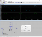
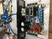
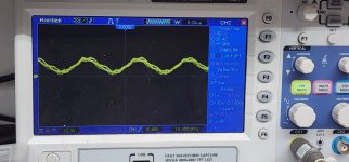
A friend who knows Technics very well and has a large collection, helped me with my Technics SU-V8X. It can not set bias, at the outputs, it had high voltage across E CB and my friend said something is wrong on the amp board.

I took out all 24 transistors ( that included the 4 MosFets). The transistors seem to test fine, had some issues with C on Q315/6, however i think that was the micro clips, not making contact, so after 2 more readings C was fine under 800.

I then moved to the MosFets and followed a video online, and i never got OL( open on my meter is 1) readings, just low numbers like 148 158 on my 3.5 digit meter, so i assume they are defective?

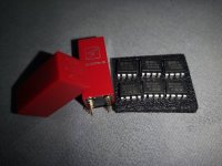
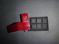
Since 2SK117 is discontinued, by chance i went through my spares, and found my spare V4X phono pcb and found 4 2SK170 mosfets (which i hope are fine, as ive stored them in a box over the years).

Specs are very similar , voltage is lower with the 170s, and it actually appears lower noise? I tempted to try them, however will check some resistors first in the path to see if there is any defective. Only difference is VFDS -50v vs - 40v, otherwise pretty close

This might be useful thread for a reference for the parts as well, i hope.

2SK117 Product details
Low Noise Audio Amplifier Applications

• High |Yfs|: |Yfs| = 15 mS (typ.) (VDS= 10 V, VGS= 0)
• High breakdown voltage: VGDS= −50 V
• Low noise: NF = 1.0dB (typ.)
(VDS= 10 V, ID= 0.5 mA, f = 1 kHz, RG= 1 kΩ)
• High input impedance: IGSS= −1 nA (max) (VGS= −30 V)
------------------------------
2SK170 Product details
Low Noise Audio Amplifier Applications

• Recommended for first stages of EQ and M.C. head amplifiers.
• High |Yfs|: |Yfs| = 22 mS (typ.) (VDS = 10 V, VGS = 0, IDSS = 3 mA)
• High breakdown voltage: VGDS = −40 V
• Low noise: En = 0.95 nV/Hz1/2 (typ.) (VDS = 10 V, ID = 1 mA, f = 1 kHz)
• High input impedance: IGSS = −1 nA (max) (VGS = −30 V)

Untitled.jpg

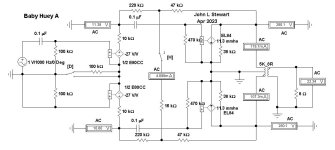
Fet differential amps Q301-304.

(if Mods think it suits the part section - please move it there, as i was not sure which of the two this belonged thanks Sam )

Crown MA 5000vz and 50002vz

Hey everyone, I have a question to anyone with knowledge about crown's 5000vz n 5002vz
Is there any difference between these two?
I hear the 5002vz does'nt preform as good as the 5000vz, not sure if that true, that why i turned here to the professionals, and also
are spare parts hard to located for these.


I tried to loacted a guy on this site who's name is "OMNIFEX" but there wasn't any luck, he seemed to know alot about these amps.

bass reflex vs double chamber reflex (ABC/DCR and DCAAV)

I would like to know if anyone has compared the systems in the figure (and possibly also the load n ° 15 type B6 by Thieele) can tell me the disadvantages and advantages of each with evidence for the aspect of impulse response or transients (also with respect to a closed case), beyond the frequency response in cutoff frequency (F3).

Attachments

  • dcr_dcaav.jpg
    dcr_dcaav.jpg
    19.8 KB · Views: 358

Cathode voltage

Hello, I am new to this tube stuff and I’m reading a book “Design and construction of tube amplifiers” by Robert Megantz.
I understand most of it at this point but there is one item he doesn’t explain well.

In this example he chose a tube, and an operating point and chose a -1.1v grid to cathode voltage. That all makes sense to me.
He then goes on to say that since -1.1v is the desired grid-to-cathode voltage, the cathode voltage should be 1.1v.
He doesn’t explain why the cathode voltage should be 1.1v. Where did he come up with the 1.1v?
I have attached the page, and highlighted the “1.1v” section I am referring to.

Attachments

  • 3646CDA1-5320-40E9-90D1-6D5BEDE7E460.jpeg
    3646CDA1-5320-40E9-90D1-6D5BEDE7E460.jpeg
    403 KB · Views: 107
  • BEE4C1A6-CD92-4503-83B1-29FF976C4294.jpeg
    BEE4C1A6-CD92-4503-83B1-29FF976C4294.jpeg
    446.7 KB · Views: 102

For sale: 4 used Peerless 830452 10" XLS Subwoofers: $50 each, includes shipping

I have 4 used Peerless 830452 10" XLS Subwoofers that I want to sell. The price is $50 each and includes USPS flat rate shipping to 48 US states (no HI, AK). These subwoofers have been sitting on a shelf in my garage for at least 5 years. They were used in an open baffle project that I took apart.
Four subwoofers.jpg
Subwoofer label.jpg
Subwoofer part number.jpg

Attachments

My E5 Class A hifi headphone amp

Hello all,
I design three headphone amps: E3, E4, E5

E4 is the upgrade version of E3, E5 is the upgrade version of E4, E5 sounds more pure and natural. And better performance in the heat sink and protection.

They own different characteristics. (E3 refer to the beyerdynamic A1 headphone, E4 refer to the JC2 dual differential FET input construction, E5 using Marantz HDAM input structure)
Some audiophiles in my domestic discuss these headphone amps, they like the E5 best.

Here are the pictures of E5 headphone amp, work on class A.

Attachments

  • DSC05364.jpg
    DSC05364.jpg
    338 KB · Views: 3,746
  • DSC05366.jpg
    DSC05366.jpg
    318.7 KB · Views: 3,482
  • DSC05368.jpg
    DSC05368.jpg
    296.8 KB · Views: 3,314
  • DSC05370.jpg
    DSC05370.jpg
    341.8 KB · Views: 3,316

For Sale Firstwatt F4 complete kit with high quality parts

Hello dear diyaudio friends

I have a complete brand new kit, consisting of four F4 channels for a balanced mono construction. Everything is included, already partly assembled. The boards are from an older group buy in the German analog forum. As said the boards are partly assembled, please check pictures for details. Q1 and Q2 are precision matched 2SK370 and 2SJ108, the power transistors are precision matched IRFP240 and IRFP9240 (Keratherm Red insulators are included). Rectifying diodes are high quality HEXFRED HFA08TB60. BIAS resistors are Mills MRA non magnetic and non inductive ones, all other ones are non magnetic Dale RNC. Power Supply resistors are green Kiwame. Electrolytic capacitors on the amp boards are all Elna Silmic, power supply caps are all Panasonic 22000uF. With each power supply, you get two tiny rectifying boards for installing the diodes. I also have two custom made high quality 500VA (230Volts/50Hz) transformers that are fully MU capsuled. One transformer weights 4.85KG.


Price for the complete amp kit: 550 Euro SOLD Only the transformers are left


I’m also willing to trade for one or more of the following items:

(Of course, I will pay difference in value)
Manufacturer sealed bags of:
  • 2SJ74-BL
  • 2SK170-GR
  • 2SJ74-GR
  • 2SK370-BL
And maybe other rare signal JFETS or dual JFETS

  • BurrBrown PCM1704-K DAC chips
  • Analog Devices MAT02 and MAT03 dual monolithic transistors
  • 2 x Starkrimson® Ultra Amp Module
  • XRK Audio RTR TPA3255 Reference Class D amplifier

Please also take a look at my other offers in the Swap Meet

Shipping:


Shipping weight will be over 10KG for the amp kit and for the chassis over 20KG.
So the costs will strongly depend on your location. I will ship anywhere in the world. Shipping costs strongly depend on the shipping method you prefer.
Of course, I will only charge the real costs, I won't charge anything for packing materials and effort. I prefer to use Deutsche Post/DHL, but you can decide which shipper and which shipping method I should use. Very secure packing by me is obvious.

As payment method I prefer PayPal for friends and family, so no extra fees will be added. Other payment methods on request. Of course personal collection of modules in Cologne (Germany) and payment in cash is also possible.

Kind Regards
Phil
IMG_1286.JPEGIMG_1287.JPEGIMG_1288.JPEGIMG_1289.JPEGIMG_1290.JPEGIMG_1291.JPEGIMG_1292.JPEGIMG_1293.JPEG

12" woofer choice for 3-way with midrange dome (Scan Speak Discovery D7608)

I am looking for a 12" (or 11") woofer for a three-way construction with a midrange dome. Woofer and midrange dome will cross at about 500-700Hz. The woofer is supposed to go down quite low, but above all to play bass with great impact. The quick, energetic with significant dynamics. The speaker must be available in Europe.

For Sale DEQX HDP-Express II speaker/room processor in the UK

DEQX HDP Express II for sale. In excellent condition. Quick summary: it's a 3-way digital active crossover, speaker equaliser, room equaliser, DAC and system preamp.

See here for a summary of its capabilities and specs: https://www.deqx.com/products/hdp-express-ii/

In conjunction with a PC, it can measure speakers or individual drivers and then create and apply correction filters to produce ruler-flat response and phase. It can apply 3-way crossovers, either conventional minimum phase or linear phase, up to 300dB per octave. You can also use it to measure your room and apply room correction. It can act as a high-end dac/preamp, with or without the other functions.

This is part of the most recent generation of DEQX processors, along with the HDP-4 and HDP-5. (These all use much newer hardware than the HDP-3 and PDC 2.6.) It has only just been discontinued recently.

These really are amazing units, and it's been the heart of my system for the last three years.

I'm the second owner. The Earthworks M23 microphone was an additional £600 option.

It has 2 analogue and 4 digital inputs, but does not have the optional USB audio input. I have a Gustard USB to spdif converter which I've used with it, and which could be included if you're interested.

DEQX units, especially this newer generation, don't come up for sale very often at all.

I'm in Glasgow, UK. Willing to ship most places. Looking for £1300 plus shipping, which I feel is a good price, especially including the Earthworks mic.

Any questions please ask.

Adcom GFA 555ii (purchased in early 1990 with no significant use in last 20 years)

The amp works and has near zero voltage at the speaker terminals when nothing is connected. I am told this is a very good sign.
I was told if the amp is faulty it can fry speakers. I still have the 802 B&W speakers that came with the amp back in the early 1990s.
Is it safe to use the amp? It works fine with the current PA speakers attached to the amp. At most I have used the amp every three or four months during the last 20 years. It blew a fuse once and I was able to replace the fuse and it continued to work OK.

Should I service the amp even if it is in good working condition?

Free Nils Frahm ticket for tonight in Montreal Place des Arts

Hello All,

For the past two weeks I've been quite sick and I am still pretty much under the weather... So unfortunately, I will not be able to go to Nils Frahm show in Montreal, an artist that I really like and was REALLY looking forward to go see him.

I'm looking to give my pair of tickets to people wanting to go, not to try to resale the tickets.

Artist : Nils Frahm
Where : Place des Arts in Montreal
Hall : Salle Wilfrid-Pelletier
Time : 8pm (tonight 2023/04/19)
Seats : J13, J15 (first floor, good seats)
Tickets will be transferred via email, as soon as I can confirm it is someone from the area.

Thanks
Do

Egg-shaped WAW idea (my latest near-field iteration)

This is the latest in an ongoing journey into new territory for me. Previous tests around the near-field theme have arrived at various (somewhat personal) conclusions:
  • My situation is indeed well suited to speakers of modest SPL positioned quite close to the listening position (say around 50cm give or take). I like this, where room effects are reduced and the neighbours don't complain as much, and yet the apparent location of instruments and vocals (etc) seem more natural to me than with headphones.
  • My first attempts with full-range drivers were very positive indeed; I'm surprised by how much I like them. However (at least with a small enclosure) it transpires that I prefer them used in a WAW configuration.
  • Speakers positioned so close can feel intrusive and also be a bit annoying for practical reasons. I've found this to be greatly improved if they are a rounded shape (rather than with corners and points), and also if they're not taking up desk-space or blocking lines of sight.
  • It is to be a bespoke creation for a slightly unusual setup, so I'd like something that looks a bit unusual too.
So... the next step will be to try egg or pear-shaped WAW speakers. I'm returning to the concept of suspending them up near ear height to leave lines of sight (and any desk, if present) in the immediate working area more free from obstruction. Something like this, but hanging or supported from behind in some way (excuse the extraordinarily crude mock-up):
28and20cm-bowl-cone-mockup_approx-12L-internal.jpg

The circles are based on (existing drivers) an alpair 5.3 and a scanspeak 15w/8530k01, which can work rather well together IMO. The mock up comprises Ikea blanda bowls in 28cm and 20cm diameters; the height is somewhat less than two stacked spheres would be, and I calculate will offer about 12Litres internal volume (before internal bracing). Probably I'd go with sealed enclosures, partly for simplicity under the circumstances and partly because I'm happy enough with how the drivers sound in them.

The alpair would want a bit less than 2Litres for a Qtc of 0.7, which would leave the 15W with sufficient for a qtc of perhaps 0.75 (depending on stuffing and braces and how the internal volume is apportioned and divided into two chambers). This will be an an active system so could be corrected in any case, but I'd just like to begin from 'approximately' suitable volumes for future flexibility.

So that is the new embryo of a plan. I don't get a lot of time off and have no workshop these days so it may take a while to realise. Combined with the complicated shape, I'll probably therefore make use of the bowls and go for a painted finish, which will allow much use of glue and filler underneath. I had considered making a mould and then using glass-fiber and resin for the walls, but that all adds to time and cost. If this works then I can always use a finished speaker as a mould later, should I want to make a fiber-glass version in the future.

Cheers,
Kev
  • Like
Reactions: GM and Mitch311

Masked part numbers, New era Amplifier

Guys, why are some manufacturers still masking part numbers even on designs that aren’t proprietary and the part itself are been re-engraved by them?
Is it that they are making the repair harder, or they only needs the item to be repaired by their authorized centers?
Have anyone seen the newer SoundStreams (Taramps look alike circuit)....
What could these part numbers be?;
The output marking H8 and what IC are they driven by?
Power supply FETs H1 and what PWM chip is driving them?
What is the error amp IC number?

Attachments

  • C0E5AE42-12D8-4C9F-B76D-58CA4F259A4C.jpg
    C0E5AE42-12D8-4C9F-B76D-58CA4F259A4C.jpg
    548.5 KB · Views: 531
  • 1AA25C7E-6B8D-44DD-B2FF-C0DA82570F19.jpg
    1AA25C7E-6B8D-44DD-B2FF-C0DA82570F19.jpg
    645.4 KB · Views: 679
  • 2C97C96D-58FA-4014-B84A-7D54D77F1F29.jpg
    2C97C96D-58FA-4014-B84A-7D54D77F1F29.jpg
    524.5 KB · Views: 553

  • Locked
Is it me, or is my integrated wired wrong?

Hi Everyone,

So for a variety of bad reasons I took my Luxman 507ux integrated amp apart. Mainly to examine up close the IEC inlet and see about replacing it. Anyway, that issue aside, it seems the amp fuses the wrong side of the AC line?


Here's the inlet as you'd see from the back of the amplifier. I'd expect the left pin to be the line, and therefore it would eventually be the fuse wire right? Please ignore the missing fuse holder except to orient yourself. The PCB the inlet is mounted on seems to be for multiple models and/or countries. The actual fuses are further down.

1681416280395.png

The issue is the wires at the bottom of the inlet, shown below:
1681416393770.png


Underneath the inlet tabs, from left to right the wire labels read BLK and WHT. This appears to be reverse of what I would expect at least in the US. Line should be black, but it's on the right.

OK, so maybe this is just bad color coding?

However if we trace the BLK wire back to the power supply control board the BLK wire IS fused, but the WHT wire is not. In the large PCB in the middle you'll find a black transformer on the right side, the wires from the inlet terminate here:

1681416541805.png


Measuring from the wiring or the pins (as seen above) it is the BLK wire which goes straight to the fuse. You can also see the copper traces underneath.

So am I completely incorrect or does this seem like a manufacturing error in the US?

For Sale Audiotechnology subwoofers (rare items)

To make some room... I will sell some units for projects that I won't build:

Audiotechnology 15E Flexunits Sub/woofer. VERY GOOD CONDITION

T/S parameters from Dayton Audio Test System: DATS V3:
Re 6.008 [Ohms]
Fs 22.61 [Hz]
Zm 37.73 [Ohms]
BL 16.59 [N/A]
Qms 3.361
Qes 0.6365
Qts 0.5351
Vas 219.4 [liters]
L10k 0.5365 [mH]
n0 0.3799 [%]
dBSPL 87.9 [1W/1m]
Ms 205.2 [grams]
Cms 0.242 [mm/N]


Need help to connect speakers to my Sansui R50 reciever

My twist locks at the rear of the amp have been removed so I thought I could connect the speaker cable directly to to power bord or somewhere closer to the power amp section. I don't understand the schematic drawings so naw I'm lost!. There must be something at the power bord to connect speakers A and B speakers or somewhere after eg at the volume knob or speaker selector switch. Please help I love this underrated beauty it just dilivers what you need.

Connecting two amps wirelessly?

Hello. My family owns a cafe, so I'm helping them out with technical stuff. They have both indoor and outdoor seating. We want to play the same music inside and outside, but there are no cable conduits of any kind (brand new governmental building with "hermetically sealed" fasade - windows over many floors). It has revolving doors, so cables through the door is not an option.
We use two normal home hi-fi (Onkyo) receivers with two iPads (one indoor, one outdoor), cabled speakers. Setup is simple to operate. But we need to connect them together without any lag.
I want to split the indoor iPad (to the indoor amp + the wireless transmitter). Then outside amp with a wireless receiver. Alternatively feed the indoor iPad signal into just the wireless transmitter, then attach receivers to both the indoor and outdoor amp. If both amps are on indentical receivers (BT mesh?), they won't have any lag between them.

Any suggestions on what to buy?

Threshold SA/1 with black face meters??

Not your typical amplifier question, more a Threshold trivia question. I have 2 pairs of SA/1 monoblocks, both black face wit the silver meters. A buddy of mine has a similar pair but just picked up a pair with black faces with black meters. They are the original meters as the amplifiers were purchased from the original owner AND they have a Threshold logo at the top. I have never seen Threshold black meters. Anyone know the history behind these? Was it a case of, "A few sitting around and we thought we'd use them" or was there an actual run of these with black meters?

Just curious!
SA-1 black meters.JPEG

Dual Mono Icepower 125asx2 Unbalanced source

Hello all, I am planning on a Dual Mono build of the icepower 125asx modules, my source is rca unbalanced. I was wndering if I could use the ART DTI transformer hum eliminator and converter instead of adding two of those RTX modules from ghent or any of the others on ebay etc. Will this work converting unbalanced to balanced?

https://www.amazon.com/ART-DTI-Tran...-channel+hum+eliminator&qid=1681288879&sr=8-4

Using A Digital Crossover with Passive Sub

Hi all.

I want to try using a passive sub (already own a JBL ASB6112) for my music listening at a computer desk. I've got spare amps and was thinking of using a Biamp TersiraForte DSP as the crossover.

When setting up the crossovers in the DSP, should I set the sub out to 80hz and below and the mains 80hz and above? Or, should there be some overlap?

BTW, does anyone have experience using a DSP for a crossover? This is a very expensive unit, but can get for free. Will it color the sound much?

Thanks!

Rockford T1500-1bd AF oscillation in XOVER card

I've got a T1500-1bd on the bench. Came in with the usual R2035 falling off the board and the LM5110s blown.

I believe the client had this unit mounted on his sub box or something, because all the little heat stakes holding the plastic lid are broken, and when I asked him why he said "the music", though he claims the amp is mounted properly. Inspecting the board doesn't reveal any obvious lead breakages on the heavy components.

Repaired the stuff in the output section, getting HF oscillations at the output transistor gates, but there's an AF oscillation coming from the crossover card (apparently: it's at the output of that card going into the EQ card, and it doesn't seem to be present at the differential input to XOVER, but it's hard to tell with all the common mode noise there thanks to the ingenious placement of the AF preamp next to the rail capacitors...) The frequency is dependent on the setting of the crossover pot, and the amplitude is dependent on the gain pot.

Pulled the HV rectifiers to make the thing safer to handle and less prone to burst into flames, still there.

I had the XOVER card out, and powered it from the bench supply for testing. The oscillation was present but lower amplitude. Was seeing an odd DC bias about the last op-amp in the chain on that board, replaced that, it looked better. Soldered it back in, it still oscillates.

Before I pull that card again (or tell my client to buy a Hifonics), anyone seen this and solved it?

Let's talk about the I/V circuit with common mode servo as shown by ES9039pro datasheet

I recently came about the I/V circuit proposed by ESS's ES9039pro datasheet. Firstly let's show it here:

schematic.png


I will try to describe how I think it works, let's see how many misconceptions I have about it...
  1. There is a "deglitching" cap (C18.1) directly around the DAC outputs. I remember that this might cause problems with I/V opamp stability. Why is this suddenly not the case anymore? I see it's benefits, forming a 1st order low pass with the DAC output resistance (I calculated a cutoff of around 200kHz with 2x744 ohm output resistance of a single DAC output).
  2. U14.1/14.2 with their feedback components from the output to the inverting inputs form a "standard" opamp I/V circuit.
  3. U15/C72/R102 make an integrator with cutoff of about 2.6kHz, taking it's input from the summed I/V output (by R100/101), seeing only common mode voltage of the I/V outputs at it's inverting input. U15 noninverting input is referenced to ground.
  4. I/V opamps U14.1/U14.2 have a positive gain of ~744 on their noninverting inputs (R14/15/17/18) where the output of the servo is amplified.
My questions:
  1. Where does the servo cutoff of 2.6kHz come from? Are frequencies between 2.6kHz and the edge of the audio band (20k) of lesser importance?
  2. Why is the servo output amplified by 744 and then works as a reference for the I/V opamps?
Looking forward to your answers, as always 🙂

Adding passive radiators to sealed bookshelf cabinets

I have a pair of Acoustic Research bookshelf speakers with voice coil rub so am going to replace the drivers using speakers from a set of Definitive Technology 5.1 speakers. However, the AR cabs are sealed and twice the size of the DT satellites. The satellites also have a single passive radiator the same size as their driver in each. I’d like to add the PR to the larger cabinets. Most research that I’ve done shows PRs being twice the size of the driver, so should I add 2 to each cabinet?

What EV rack equipment was made in Germany?

Hi guys,

I recently bought an EV AC1 audio controller, which is a subwoofer crossover that includes basic but useful tone controls. This unit is made in Germany and IMO is very well built with good parts and parts layout.

I tried searching for other gear that EV made in Germany, but the AI searches couldn't find anything.

Does anyone know how to find the other gear EV made in Germany?

Thanks,

Scott

Help with Philips CD changer from the 80's (dead SAA7210?)

I recently picked-up a Philips CDC486 six discs changer from a flea market. Sound-wise it is a pretty standard Philips of its time with CDM 4/20 and TDA1543 as DAC. It appeared to have only mechanical problems and I tried to took care of that. Before embarking in the restoration, I tested if the CD player part was actually working and in service mode it successfully locked focus (phase 1), track (phase 2) and disc rotation (phase 3); after one minute it then started to play music and I was happy and continued restoring it.

After stripping down, cleaning and fixing the cd-changer side, the player side appears to no longer works: on power on the disc spindle starts rotating at high speed and everything appears to be stuck. I am able to load disc and in that case disc rotation is slowed down and the pick-up seems to lock to the track, but there is no play back.

I tried again the service mode and this time I'm greeted with what is shown in the attached pic. I have retouched all possible solder joints, I have checked connections and voltages and everything appears to be correct. I have read else where that behaviour might be caused by a faulty decoder chip SAA7210: is that the only option ?

What could have I done wrong to kill it ?

thanks

further note: the display works correctly in normal mode, so it is not a problem with the display or the main CPU itself

Attachments

  • IMG_4225.jpg
    IMG_4225.jpg
    308 KB · Views: 92

How to wire transformer with 3 inputs (to replace one with 4)

Hi guys,
Wanting to replace an existing transformer (to fix hum and for fun of learning), I ordered a new one, in 2x115v to make it an easy replacement but it arrived as a 230v.
I’ve read about serie or parralel wiring but didn't find anything about the 3 wires only case.

The original has 4 input and output wires:

IMG_2385.JPGIMG_2386.JPG

The new one only has 3 inputs / 4 outputs:

IMG_2387.JPGIMG_2388.JPG


I feel ok to wire the outputs, black/black instead of blue/blue and w/w instead of brown/brown.
But how should I wire the 3 inputs on the 4 pins input connector?
Thx!

FS: 400VA 2x45V Supreme Audio Grade toroidal transformer from TOROIDY

For sale this superb 400Va toroidal transformer from Toroidy.
It's the Supreme Audio grade version, it means You'll get transformer wound on highest inductive, laboratory selected and tested core. For a best noise reducion core and all the windings are impregnated . Transformer will also has electric and electromagnetic shields. Whole transformer is vacuum encapsuled, epoxy filled in a polished, stainless steel box. Zero noise whatsoever and it's new unused.
2X45V output you can build and amp that works at +/-60V
I paid for this over $200 including taxes and shipping from Poland.
Asking $125 USD plus shipping.

Attachments

  • Toro1.jpg
    Toro1.jpg
    277.2 KB · Views: 142
  • Toro2.jpg
    Toro2.jpg
    359.4 KB · Views: 142
  • tempImagekYaivG.gif
    tempImagekYaivG.gif
    1.1 MB · Views: 144
  • Like
Reactions: Gill.T

Simple two triode preamp - PCB layout questions

I have built a few PTP tube preamps and I would like to learn more about PCB design with tube circuits.

I am starting with a very simple two stage preamp (vintage RCA BA-2C schematic) using two 6J7s connected as triodes.

I have attached a schematic of this circuit and the layout I have come up with. I have a few doubts regarding the following :

- Ground planes : I have been doing some online research on the subject and from what I could understand the high impedance of tube circuits can be problematic if using ground planes because the parasitic capacitances can cause oscillations and loss of treble. Can this be avoided by considerate spacing of the ground plane from the traces and pads ? What would be the recommended isolation of the ground plane ? (I have set it at 0.035" at the moment)

- I have chosen to use DC heaters to simplify wiring and perhaps reduce noise.
I have routed the heater traces on the top layer, along with the ground plane, and on the bottom layer I have all the signal traces and B+power supply lines.
Would it be preferable to place the ground plane on the same side as the signal traces ?

Attachments

  • BA-2C layout.png
    BA-2C layout.png
    131.3 KB · Views: 192
  • ba-2c.gif
    ba-2c.gif
    235.8 KB · Views: 179

NSM 4002 display - good news

Hello,
Possibly good news for those looking for an easy fix to those failing displays on early CD players.

Lite-On
LTM-8328PKR-04

is a direct substitute, pin correct and physically identical. Only problem is that its RED.

Available from Mouser and Digi-key. MOQ: one.

There is also the Lite-On LTM-8328GKR-04, which is green, but unfortunately the MOQ at both these suppliers is ....570.

Maybe if enough people bug them, they'll order 570 for themselves, so we can buy in small quantities.

Also, its less than $15 ;-)

I just fitted one to my CD202 and its better than the original as it has a black face, rather than the light grey of the original. It disappears when not operating, seamless on the front panel.

Power Devices for F5Turbo and how does the F5 sound

Hello everyone out there!

I have been a passive reader of this forum for many years. Unfortunately I couldn't log in anymore, so I registered again today.
I learned a lot here, special thanks to dad Mr. Nelson Pass for his great work and creativity.

I built an ACA in parallel output configuration with a linear power supply as monoblocks.
Sony's Sony TA-NR 1 monoblocks are available to me as reference amplifiers.
Dynaudios Confidence C1 must be powered.

Now I have the following problem:
The Sonys offer clarity, spaciousness, resolution in the high frequency range and the ACA brings the warmth and grace in the voices to my ears.
I don't want to do without both, so I would like to build the F5Turbo or the AlephJ or the F6.
Can you please briefly explain the tonal differences between the three amplifiers?
What could be the best amp for the Confidence C1?
The F5 has the most power...but is wattage everything?

A specific question:
On 2009-08-10 Mr. Pass wrote:
One of my current favorite mosfet pairs, the Fairchild FQA12P20 and
FQA19N20C are scheduled to be discontinued before the end of the year.
And John China: I use FQA16N25C and FQA9P25.

Unfortunately the FQA 12N20/19P20 are no longer available, I can still find some 16N25/9P25 suggested by John China.
Do these offer me a sonic advantage over the generic IFRP240/IFRP9240?

Thank you for your help, greetings from Franconia in Germany!
Mike
Projects by fanatics, for fanatics
Get answers and advice for everyone wanting to learn the art of audio.
Join the Community
507,948
Members
7,895,370
Messages

Filter

Forum Statistics

Threads
406,561
Messages
7,895,370
Members
507,948
Latest member
AMDguy