
Isn't 5VDC on the mains excessive? With normal silicon diodes across the large 'lytics, I'd hazard that it'd only work for less than 1VDC.
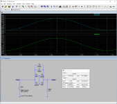
Use 20 pairs of antiparallel diodes in series and simulate for 60 seconds to give the circuit time to settle.
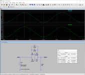
Your timestep is too large. I have simulated it with a smaller timestep, and it works as intended.@knutn: i removed the dc voltage item (V1dc) and put the 5vdc in de V2ac as you mentioned but nothing changed.
See attachment.
That's strange. Abraxalito and I see by inspection that it can never work for DC offsets greater than the sum of two diode forward voltages.
Yes, it's only for testing.Isn't 5VDC on the mains excessive? With normal silicon diodes across the large 'lytics, I'd hazard that it'd only work for less than 1VDC.
What timestep you choose? Even with 1m it didn't work for me.Your timestep is too large. I have simulated it with a smaller timestep, and it works as intended.
Use 20 pairs of antiparallel diodes in series and simulate for 60 seconds to give the circuit time to settle.
Actually, this is a mistake. It can't work in real life at 5 V DC, because the reverse voltage across the electrolytic capacitors gets too large.
I simulate it with 1V and that works, maybe you're right that it only works at max forward voltage of the diodes.That's strange. Abraxalito and I see by inspection that it can never work for DC offsets greater than the sum of two diode forward voltages.

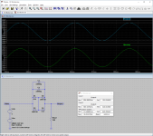
It works. The maximum voltage drop for the capacitors is two diodes in series. So it's not a problem with 5 V. But one can not use 1N4148 diodes in real life. I have also simulated with 1N4001 diodes and a timestep of 1/1000 of the time period (Remember 50 Hz is 20 ms period, so time step of 10 ms is far too large).
Rather than put the 'lytics back-to-back, I'd connect them in series (in opposite directions) so neither sees any reverse bias. But of course you'd need to increase the values to compensate.
- Home
- Design & Build
- Software Tools
- LTSpice - DC Blocker