Cairn 4808 amplifier repair help

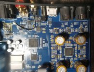
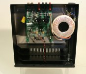
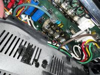
Bought this as not working and has been modified . Someone has had a go at fixing this but thats the only info i have . The mods consist of bigger supply caps changed from 4x 4,700uf to 22,000uf 😱 the rectifier package on the pcb has been removed and replaced by a another one attached to the heatsink
the fuses x4 where moved to the back of the pcb and most of the capacitors have been swapped out for panasonic fc then bypassed with film caps under the pcb .

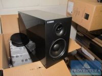
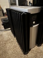
the case alone is worth what i payed for it not to mention the Eichmann Cablepods on the back 🙂. On powering it up after a few seconds the relay for the speaker output clicked in so i connected my stunt speakers and although the source selector and volume control worked on the lcd display nothing from the speakers .

Checked the 2x big transformers all ok 2x 20v. the front display lcd and input selector relays are fed from a small transformer on the front panel pcb .
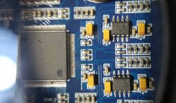
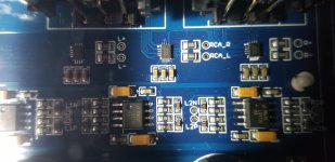
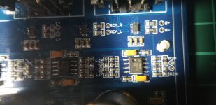
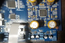
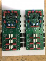
So the big transformers just power the output . Decided to remove the pcb to investigate further see pics . Removed the 4x supply caps and removed the output mosfets on the heatsink which all tested ok . removed the fuse holders and put them back on top of the pcb .

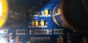
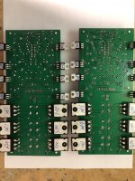
After studying the board i noticed a voltage regulator was missing i traced the tracks to a PGA2311 volume control chip on the back of the pcb after looking at the data sheet of the ic i found out it needs a +/- 5volt supply so i have replaced with new + and - 5v regs .

I have probed most of the components with my component tester on my Hameg hm605 oscilloscope and none where short all looks good .

I am hoping its just the supply to the PGA2311 and thats it 😉. What i would like to know is am i better to replace the main power supply caps with 4,700uf original caps as the 22,000uf wont fit now i have moved the fuse holders back didnt want to leave them under the pcb as it needs to be removed to replace fuses.

Looking at the build quality of the amp i dont think they used 4,700uf to save money ! Whats your thoughts on that ?

here are the pics....

An externally hosted image should be here but it was not working when we last tested it.


An externally hosted image should be here but it was not working when we last tested it.


An externally hosted image should be here but it was not working when we last tested it.


An externally hosted image should be here but it was not working when we last tested it.


An externally hosted image should be here but it was not working when we last tested it.


An externally hosted image should be here but it was not working when we last tested it.

Newbie wants 845 SET Monoblocks

Hello. I recently had my Willsenton R800i 845 burgled from my home along with some digital equipment and some speaker transducers. I have built a Troels Gravesen TL1 which is 95db sensitive and now I have to get another power amplifier(s). I fell absolutely in love with the sound of the 845 and I believe it sounds so good because it has enough power to drive all the speakers I have given it, but it is still a SET and still sounds so sweet.

So, instead of buying another stereo integrated or anything else, I want to build my next amp. I am not sure if building an 845 amp as my first amp build would be appropriate and so I might end up building a solid state class-A or even a higher-lettered class amp just to get things started.

I wanted to ask if there are any designs of 845 monoblocks that I can work towards building? I want point to point wired and as simple as possible with no features other than power amplification. I know relatively little about electrical engineering but can read diagrams, build crossovers and cables, have my own soldering setup and am on the passive preamp-builder level in terms of components. I don't have a lot of testing gear like a good oscilloscope (I have a cheap DIY version), but I can buy more over time.

If you don't know of a design that I can use for 845 monoblocks, maybe you can point me to a simpler design that will (sortof) meet my tube needs?

I can't really spend a ton of money because I am having to replace several components from the burglary. My thoughts are that I could spend up to $1,500 per monoblock. If I do not use 845 tubes on my first build I want to keep it affordable, like $500/monoblock so that my learning doesn't start to consume my entire financial income.

The primary purpose of this amplifier is to power the TL1, a full-range 95db sensitive hornloaded loudspeaker that is already in my home. I don't need a ton of power but want at least enough to run these beasts. I don't know if 300B tubes will put out enough power, but can anyone help me get started on my journey to finding the design that I want to build?

I went from not being able to build speakers to building world-class ones (in terms of design....im not bragging about my build skills) in about 3 months so I think a similar amount of time devoted to the art of amplifier building could yield the results I seek. I have many many hours a day to devote to the task and the only impediment to forward progress is money.

I look forward to hearing from you and happy DIYing!

Newbie confused with mixer and connections

Hi everyone. Nice to be here. I recently purchased a new powered mixer for my gospel music ministry. I’m confused about a couple things. On the front of the mixer is a Jack and it’s labeled” Monitor” above the Jack and “to ext amp” below the Jack. And on the back, one output is marked “ Main Main” and the other is marked “ main monitor”. Ive got 2 speakers for the house, and 2 powered Alto monitors. Please help with the proper hookup! Thanks all!

Digital Preamp

Hi all, I'm needing a product, a preamp of sorts that takes 2 or more Digital inputs and outputs to digital coax spdif. I would like to use it With my Hypex fusion amps. A volume control and remote would be great as well. I could not find this subject anywhere in this forum. Hopefully somebody knows a suitable product. I dislike toslink because of the awful connection quality. Thanks in advance

Amp Needed For Acoustic Waveguide Guitar - Patent Submitted

Hello all - I am looking for an amp to install INSIDE my Acoustic Waveguide Guitar. The patent has been submitted but not granted yet. I do have another granted patent for this product titled Folded Horn Acoustic Guitar (Patent # 10,777,172). Check it out on Google Patents. I posted this a year ago on the Instruments and Amps forum, and have had excellent feedback, but I wrote a new patent based on testing, and changes being made. I am not trying to post the same info again, which focused on the guitar design, construction and audio requirements, but now need some info regarding the electronics. I cut the electronics out of a Roland Acoustic Guitar Amp AC-33, and can fit inside my guitar, but just barely.

I would like to know if anybody is interested in building an amp and controls that are similar to this, but smaller if possible. I would purchase this to go into my DIY project. I have my own 3" full range speakers, 20 watts, 4 ohms, and the Roland is 15 watts per channel, 4 ohms. I am also using a Fishman piezo pickup/preamp to power the amp. The Roland AC-33 is battery powered, so this guitar can be played UNPLUGGED.

It is 20 dB louder (4X) than a standard acoustic guitar, and the internal waveguides (with horns on the end) are five feet long (two of them). This captures 1/4 wavelength of the lowest frequency on a guitar (approx. 85 Hz). The lows are incredible, a great acoustic guitar sound. Add a little gain and reverb, and this thing sounds like an old maple Gibson hollow body electric, maybe because the body is CNC machined from a solid piece of hard maple (6" x 18" x 24" before machining), and the waveguides are covered with 1/2" Baltic Birch. There is an upper chamber above this also, stand acoustic chamber. Maybe some people will add comments from the past thread (hope I am not double dipping). See attached, as Franklin said "our critics are our friends, for they show us our faults". Bring on the comments and thanks! Joe K

Attachments

Double 12 port question

3463BC4E-9B1D-4580-964A-27182A137CC6.png
Hi there.

Will the port arrangements in the photo below function the same?

The view is down from above the box. In each case the port is a slot that spans the entire cabinet vertically (it forms a rectangle by butting against the walls).

I was thinking perhaps the short sections in the second picture need to be half the volume of the long section or similar?

Thanks

Topping D90 help

Accidentally a mic cable with 48V has been plugged into topping d90.
There are some 16 pin muting chips on the output. 1 for each XLR and 1 for rca. The left XLR chip (the one received 48v) has L+ and L- connected now so it is gone.
The audio still doesn't come from neither from R XLR nor from RCA.
So I am wondering how deep can be the damage and I would greatly appreciate some suggestions on how to find the failure.
3 Lme 49720 opamps in the buffer output
and 4 1612 in IV satge

Attachments

  • 20220203_001358.jpg
    20220203_001358.jpg
    402.3 KB · Views: 444
  • 20220203_001321.jpg
    20220203_001321.jpg
    287.8 KB · Views: 443
  • 20220203_001146.jpg
    20220203_001146.jpg
    273.7 KB · Views: 474
  • 20220203_001612.jpg
    20220203_001612.jpg
    595.7 KB · Views: 575
  • 20220203_001624.jpg
    20220203_001624.jpg
    444.9 KB · Views: 649
  • 20220203_001649.jpg
    20220203_001649.jpg
    478.1 KB · Views: 435
  • 20220203_001456.jpg
    20220203_001456.jpg
    219.7 KB · Views: 428

Direction of capacitors outercap

Hi, can you tell me whats the right way to mount a capacitor. The capacitor has a inner and outer foil. The outerfoil is working as a shield to prevent noise entering the innerfoil.

So, I thinking then when using a cap in line with the signalchain as between output on PCB and RCA in a dac or preamp. I think signal from PCB entring the outerfoil on cap then to innercap and to RCA ( outerfoil works as a shield, not letting noise entering innerfoil ).

If turn around the outerfoil is picking up the noise an sending it down the signalpath?

Or am I wring here? The rule say outerfiol pointing the less impedance way to ground.

HELP!! ( :

ML Aerius power supply blowing fuses

Hi all, I'll jump straight in and ask for help. After a bit of fiddling around I found that the fuse had blown and following a few of the threads and advice from an ESL builder and parts supplier (WA in Oz) ran a feed from the working panel to the dud and the panel works. I now have been able to remove the access door to inspect the power supply, armed with a circuit diagram from ML US and confirmation that they do not supply component parts (if I find the problem) and to contact a local supplier for a complete board ($$$)

The board itself and components all look in good condition with no obvious signs of overheating, tracking or loose connections. I have checked out the resistors and diodes on the pcb with a multimeter in situ and they seem ok. Which sort of gets me to the extent of my knowledge. From various conversations I read the transformer(s) are often a problem. There is a small one mounted on the pcb without id and a larger one with 486-071091 486-9230 stamped on it. Can anyone suggest my next move, how do I test them? Is more information required?

A forward thanks to anyone that can help, and apologies to the mods if I've posted in the wrong area. I'm in Australia so comment timing may be a bit disjointed.

QL Hornresp

Hi there,

I've had a good search through the hornresp manual and google searches, but I cannot find any explanation of the 'QL' parameter. This is for a bass reflex subwoofer.

I can see from manipulating it that it affects the size of the lump in the low corner created by the port. I see Hornresp refers to it as 'Quality Factor'.

Roughly, I'm guessing it means losses due to natural factors such as the sound lost to cabinet resonances etc. But how do I adjust the QL parameter to represent what my built enclosure will sound like? Or is it best just to leave it on 7 and see how it comes out?

Thanks

TPA3116 XH-543 board short troubleshooting

I was working on a build, following CyberPit XH-543 Mods
All I've done so far is my own mod, removing the onboard pots (I have 10k pots on the signal input side) and bridging the two pins necessary for it to work.
I was testing it after doing that mod, 600hz sine wave and had audio output, 10.5volts AC across the output leads when my external pots were turned off (they were backwards). I turned it off and flipped around my pots and turned it back on, it was working correctly.
I had set the heat sink ontop of the chip and accidentally knocked the board, I saw a spark on C26, a 1uf cap I believe according to XH-543 diagram, and now I have no output at all.
I replaced it with one of the ceramic 1uf caps (after testing with multimeter) from an older XH-543 board I have. I turned it on and saw voltage, but it quickly started plummeting until it hit 0.
How do I troubleshoot this board and figure out the issue? I already bought a new one, so it's not a matter of it not being worth it. I'm fairly new to electronics and would just like to understand the methodology to try and fix this one.

UnitedSIC UJ3N065080K3S SIC FET Amplifier Design Idea

design idea to use UJ3N065080K3S PowerJFET.

Kokorian shared his SRPP design concept to me. He gave the following information:

"The lower jfet adjusts the quiescent output voltage, the upper, the bias current. The P jfet keeps the voltage of R1 +R2 constant, by this it modulates the upper jfet current inversely to that of the lower. All values are to be considered as demo."

I

Attachments

  • SIC-powerjfet.JPG
    SIC-powerjfet.JPG
    46.3 KB · Views: 398

Assembled Denovo Audio Subwoofer Cabinet for 18" woofer - $100 (North Phoenix) Pickup Only

Local pickup only in the Phoenix, Arizona area.

Denovo Audio MDF 4.0 cu. ft. Subwoofer Cabinet for 18” Subwoofer, excellent condition

https://www.parts-express.com/Denov...r-Dayton-Audio-18-Ultimax-300-7089?quantity=1

Unassembled MSRP: $248 (not including acoustic foam, mounting hardware, cabling or input connectors).

4.0 cubic feet • External dimensions: 23" H x 20" W x 20.75" D • Mounting depth (mounting baffle to brace): 11" • Subwoofer recess: 1/2" • Weight: 62 lbs.

Bolt locations at 440 mm = 17.32" (17.32" = 17 5/16") were installed for a B&C 18 TBX 100 driver, but should fit most common 8 bolt 18" woofer frames.

Included: acoustic foam, (8) machine bolt fastener kit installed, nickel plated binding posts and high quality driver cable.

$100

2023-04-15_124011.png
2023-04-15_124058.png
2023-04-15_124128.png
woofer bolt holes.jpg
  • Like
Reactions: manniraj

Class AB Amp Class A conversion

Hello Friends, I Have a Question
Example: I have an amp

Class AB
2x200w RMS Power
+/-65V Supply Voltage
Input impedance resistance 56K

Well, for this amp to be A Class, if I increase the input impedance resistance from 56k to 100k and make the supply voltage +/-45V, the RMS and Db ratios will decrease, then can we say that it is A Class?

What is the reality of such an event?
  • Like
Reactions: HeyBill

Coupling Capacitor choices

Hello:
I just restored an ST70. It is articulate and detailed. Got rid of the tubby bottom end. I also use a SS rectifier which is a listening preference. The tube rectifier sounded like the amp had a head cold. I'm using KT77 tubes.


So now it is time to choose the dreaded coupling capacitors. two choices stand out. SGO EVO Mundorf or copper Audyn. Also was considering a West Cap NOS. Looking for something that is efficient, doesn't add much to the sound but delivers the detail I worked hard to find in this circuit.


Does anyone have experience with these? I have read a lot but this question requires experience Please be reasonable but what would be your suggestion? Throwing out metalized PP @ .50 cents and at the other end of the spectrum caps that cost more than my car! I have an 80 dollar budget.


Not looking for debate just advice. Thank you all for your help. Im sure your experiences will help bring me insight.

Yamaha BP110 help with Crossover

Hello , im new on this forum .
I am Audio Doctor , i work with audio files , repair damage , remove noise , do Mastering and such .
But i got some listening speakers .
Since my room is small , i got small speakers , couple of them but for this time Yamaha BP NS 110
Very nice speaker, very fast , has nothing on the woofer goes directly to the amp , its a 3-4 inch woofer says 6 ohms measured 3.5Ohms DC , hence its fast .But it doesnt go low , about 60hz with box 50hz. Yet to be measured .
And on the tweeter it has 1uF (microFarad ) Capacitor in series , i trust its not very god one , but i measured the value at 1.24 uF and the tweeter is 6ohms , measured 6ohms .
Of course this is DC .
Now when i enter those values in Crossover calculator , i get 22khz cut off , that is impossible , because i hear the tweeter
So we have bass going directly to the amp , and in parallel with the tweeter that has a capacitor 1.24 uF in series on it .
I have measuring gear , and will ultimately measure it .
But if someone could help me with this calculation , one im doing is obviously wrong .
I opened up the speaker , immediately , since im very good in Electro Acoustics , in fact i have bachelors degree in Electroacoustics .
I saw it has bracing , but is not filled with foam of some kind , so i filled it up .
The reason Foam is put in , is because sound travels slower in harder material , so basically with putting foam in it you get bigger speaker , sound wise .
I also used kind of Rubber metallic sandwich that is labeled Ground Zero and used in cars , so that Car doors and such dont vibrate , its antivibration tool
I added a bit of that , bad thing is that it effecticly makes the box smaller , but i added a foam , so i guess im at equals now , but i have notices much tighter sound .
So it works .
its all good .
But now to the Crossover , there is lots to say about them , but complex big crossovers eat up transients in sound , so i avoid them you may not , its my preference , and use only small 2 way speakers that can go without crossover , with only capacitor on the tweeter to filter out the bass and mids to extent .
Now can someone calculate for me the Crossover frequency
Bass unit says 6ohms but i measured it at 3.5ohms DC ... disconnected from tweeter of course .
So that you have all the info that you need .
Ultimetly i plan to measure them , and maybe add difrent Capacitors a matched pair , and maybe a small coil on Bass driver , i dont want to go big there not to eat up the transients .
I used to make Valve Amplifiers with Transformers on the output , so there i learned how bad it is for transients , mostly higher frequency's but also low in case of Valve amplifiers i didnt get the bass at all , so i use Valve Preamps . That can go without transformers hence has bass .
So if anyone can help me with the Crossover much appreciated .

Attachments

  • Yamaha.jpg
    Yamaha.jpg
    12.7 KB · Views: 236

Why are there only disastrous PCB Versions for TDA7293/TDA7294/LM3886 etc. available?

Why are there only disastrous PCB Versions for TDA7293/TDA7294/LM3886 etc. available?

There are an extremly wide range of PCBs and Kits available for this and similar other monolitic audio amp ICs.
For me unfortunately the position of the copper conductor tracks are absolutely
disadvantageous by all examples, which are to find by Google image search - go to

audio amplifier tda7293 - Google Search
audio amplifier tda7294 - Google Search
lm3886 - Google-Suche

By this high resolution example - go to
F200# Audio Enthusiasts DIY AMP TDA7293 Amplifier Board for sale
you will see, that the positive voltage supply rail and the negative rail goes very close to the signal pads and inverted input pad for NFB. Additional there are only cheap caps for the power supply in use without screw terminals. Consequently a certain standart of sonic quality cannot be exceeded. By all showed images unfortunately this situation I note.
I am almost certain, that nothing of the showed versions from image-search sounds really good (at best like Linn's LK85 in genuine condition - i. e. with original part and wire equipment).

After performed tweacking of Linn's power amp model LK85 (equipped with TDA7294V) I observe an exceptionally enhancement by sound quality due to additional use of caps with screw terminals and change the routing of the wires for the main voltage rails.

According to my requirements four holes would be drilled in the PCB near by the pins 13 and 15 in case of TDA7293/TDA7294 (in opposite of the sensitive area). The cans of the caps must go downward (solder side/bottom side) and the screws for the caps must be screwed from the component/top side.

Then I avoid interchanges between the (very short) supply rails to the sensitive areas and I get the possibility to use top class capacitors in outlines like that from
http://www.audiocap.co.uk/ekmps/shops/audiocap/images/als30a153ke063.gif
or
http://s.eeweb.com/resized/images/r.../2011/02/15/vishaycaps-1297787376_455_332.png
instead low cost high CV versions in "snap in" outline.

Are such printed circuit boards really still not available ??
If yes, is this unbelievable. OTOH - there are too many copies of copies (clones of clones), particularly in far east.

Where is the excellent engineering from early days concerning proper PCB design ??

Attachments

Service manual for Yamaha RX-V585 wanted

Hi all

Im looking for a service manual for a Yamaha RX-V585. I googled for hours but without any success.

We have regular power outages in South Africa and it seems like this is what caused the "power on" to be disabled a safety precaution. Currently the amp is stuck in this "protection loop" and a found some info regarding someone that had the same issue. He resolved it by shorting pins 2 and 3 on the EEPROM. Holding down the suggested combination of buttons to get to the "protection state/protection reset" doesnt do anything. The only response I get is by pressing and holding "Info" and the power button. This takes me to the USB firmware update. Other than that the protection state remains.

Im not 100% sure where it is on this amp and dont want to take any chances without knowing for sure. The closest service manual i could find was for the RX-V577 but unfortunately it didnt help as the is board slightly different. Any help will be greatly appreciated.

Regards

Correct power supply & audio in for JLH1969H

Hi all, I've done a search. I found a similar power supply issue thread from back in 2017. It didn't say at the end what he used and if the supply worked.
So I've just built up hood 1969 amp off eBay, getting back into one of my favourite hobby's, I've got spare time off work.
I didn't realise when ordering the kit, no cables or power leads included.
I've done some looking around and found a few bits that I think would do the trick. Just want to make sure I'm not buying the wrong things.
So audio in has 3 pin holes, ground, left, right. I've looked for a lead to fit this and cannot find anything.
Thinking of wiring up this to the holes as the input.
Screenshot_20230425-195956.png

Now the power supply is the main issue. This will be my first attempt at fitting one, so don't want to blow the amp, or fry myself.
The 2 I've found look to be the correct type. I just need a to find an enclosure to case it in along with the amp .

Any advice would be a big help. Thanks.
IMG_20230425_192529_522.jpg
IMG_20230425_192551_979.jpg
Screenshot_20230425-201357.png
Screenshot_20230425-201326.png

Help finding out transformer specs

Hi there!

I received this ak-450ub and I'd like to reuse the parts. It had a TDA7377 and was advertised as a 200W system, which is way above of what the chip specs says. I noticed that the voltage fed to it was 21v, datasheet says that max is 18.

Regarding the transformer, how many watts/amps can I get from it? I couldn't find an identical one with image search. I'd like to use it with a linear regulator to power a TDA7850.

1682441589768.png


1682441538836.png

FS: Dartzeel NHB-108 Clone, Amplifier boards, 3 output pairs and DC adjust

I have for sale these Dartzeel NHB-108 amplifier boards. I built one for myself with 2 output transistors , I removed one pair and it sounds amazing.
I wanted to build a second one but due to budget cuts I had to cancel the project.
The output transistors MJL3281A and MJL1302A, and drivers are all matched, as you can see from the picture the values are written on the back.
Note that these boards don't have the DC servo circuit. You need to adjust it manually from the pot and is very stable, no need for servo, trust me.
I tried with the servo but didn't like it, it affects the sound a little so I remove it. I found the DC offset very stable within 5 to 10mv
This is he best amplifier I built so far, very musical and also quiet, no noise.
Asking $140USD plus shipping.

Attachments

  • Photo 2023-02-06, 5 53 27 PM.jpg
    Photo 2023-02-06, 5 53 27 PM.jpg
    466.2 KB · Views: 853
  • Photo 2023-02-06, 5 53 55 PM.jpg
    Photo 2023-02-06, 5 53 55 PM.jpg
    484.7 KB · Views: 716

Need Help in Designing 3-Stage Discrete Amplifier

Hello, I am new here, I read some guides here while I was also trying to design my amplifier and thought of making an account and have my design be reviewed here.
So, my audio power amplifier is not really mine, I made it while following along Bob Cordell's book on Audio Power Amp. design. Here it is,
Audio power amplifier.png


It is a 15W amplifier with 8-ohm load. I am having output problems as I cannot seem to meet that 15W requirement. My closed loop gain is 28 and with 570mV input, I should be able to get 15.96Vpk output, enough to reach and go over a bit to the 15W spec requirement but I am getting a lower output voltage. Also, is my +17V -17V supply good or I should go higher? I am somewhat limited to that as I am planning to re-use a 12-0-12V 3A transformer from a previous project. I am also thinking of changing my output transistors (Q12 and Q14) to TIP2955 and TIP3055 as they seem much cheaper, but I do not know how to choose the transistor to be their drivers.
------------------------------------------------------------------------------------------------------------------------------------------------------------------------------------------------------
The design is not far from the circuit from Cordell's, I have my CFP output stage to have a quiescent current of about 100mA, I achieved that by experimenting values on the Vbe Multiplier resistors. The 22pF Miller Cap value, I followed how is it calculated from the book. As for the LTP quiescent current it is at 2mA and the VAS stage is 7mA. I do not have much knowledge on how to do the output network (Zobel) I just followed the typical values mentioned in his book.
------------------------------------------------------------------------------------------------------------------------------------------------------------------------------------------------------
After that, any suggestions? recommendations? or something I should do?
Attached is also the LTSpice Simulation file already included the models I used in which I would also like to thank and credit Cordell.

Attachments

Solid State vintage Integrated Amplifier and Stereo Receiver close to Class A like Musical Fidelity A1

long time ago I start this threads:
https://www.diyaudio.com/community/...ntegrated-and-power-amplifier-devices.146528/
https://www.diyaudio.com/community/...dels-quasi-complementary-power-output.157430/

Now I am looking for an overview of vintage stereo receivers and integrated amplifiers with much more quiescent current through the output stage than the typical class B value between 20-50mA for quasi - and true complementary BjT power devices and 100mA for both only N- and N-/P-channel power MOSFET's.

A good known example is Tim de Paravicini's design for Musical Fidelity (A1, A100 etc.) - go to
https://www.markhennessy.co.uk/mf_a1/technical.htm
The Designer:
http://www.ear-usa.com/tim-de-paravicini
(Hiraga's "Le Classe A" and Pioneer's M22 unfortunately are power amplifiers without attenuation (volume control) and input selector).

Probably there are many more models in this kind.
Thanks for some advice.

Documentary: Why Europe Lost Semiconductors

A new YouTube doc from Asianometry ... seems to be quite comprehensive, but ignores audio devices like Philips TDA and SAA series.

"Lost" is a subjective term. Maybe Europe decided they did not want to go into the semiconductor market -- too many resources required, and too much effort??? Even US, the semiconductor "leader", outsources most of it fab work to Asia. Cheaper labor there.

Login to view embedded media

Nearfield Speaker using RS150P-8A ND25FW-4 Crossover Design

Hello guys,
I am looking for an experienced speaker designer that could have a look at my crossover.
I currently own C-Note's that I built some time ago but unfortunately my woofers have developed voice-coil rub after I turned them too loud on a party.
This inspired me to design a speaker by myself. I like the tweeters which is why I want to keep them and like the idea of having a waveguide for directivity.
So I want to upgrade on the woofers and chose the RS150P.
I looked at other designs using them like the "C-Killa" by Rob Elder which I took inspiration of since my enclosure design, by 1 liter, is just slightly bigger than his.
I adjusted some values for the woofer to make it more fitting for the Paper version. I want to try to keep as many crossover parts of the original C-Note as possible.
Crossover is adjusted for baffle-step. Just trying to check if there is anything entirely wrong with the crossover. The impedance curve looks kinda wonky imo, should I worry about that?

Crossover.png


Appreciate any help I can get. Thanks for your time!

Musical Fidelity Trivista 300 Volume Issue

Hello everyone,

I've got a MF Trivista 300 integrated I just picked up (for a temporary replacement while my other amp is being fixed) and it seems the previous owner wasn't all that truthful about the condition of his amp. Got to love my luck. Anyway, I find myself in a position that I have to try to fix what I have with the much needed help from you lot.

The amplifier seems to play just fine with no distortion or obvious signs when playing at moderate levels of volume. It is when you go past the 11 o'clock mark on the dial that suddenly the right channel will immediately jump to a very high volume and will not adjust up or down unless the knob is just below a very specific point at 11 o'clock on the dial. The left channel will go up an down the entire range linearly despite the right channel being 'stuck'. Below 11 o'clock they work perfectly fine in a linear fashion and at the same volumes .

Again, this is a very specific spot on the dial where it acts almost like an 'on' and 'off' switch on the right channel from being at normal volume and then jumping suddenly.

The dial does not produce noise when moving up or down which leads me to believe it is not just a matter of cleaning the potentiometer, but something in the preamp section (perhaps?). What do you guys think is the issue and how could I fix it? Thank you all in advance!

Tweeter by size - smallest outer diameter

Hello,

I'm looking to find a small tweeter by outer diameter. My current smallest is the Vifa OX20, with a OD 33.4mm. But I need something than 30.4mm

Anyone used any super small tweeters for small spaces?

1/"2 dome is probably too small for me. I'm looking for something larger, up to 3/4". Soft dome hard dome. Beggars can't be choosers.

Please advise.

[FS] Europe: Monolith Magnetics SA-09 OPT (300B)

I don't see myself doing anything with these in the coming time realistically, need to make some room and create some budget for another purchase.
Monolith Magnetics SA-9 Amorphous core 3.3K primary - 4/8/16 secondaries / 80ma for 300B.
Excellent condition, like new. In original carton. Location Utrecht, The Netherlands. Can ship worldwide at cost but probably most sensible within Europe.

€700 for the pair.

Subaru 2024 Crosstrek speaker update

Getting a new ride and I know i will want to trade out the speakers.

First, I need to get the car. But after that, I am curious how the car measures with a mic

I don't know how much room I have for parts.

I think it would be cool to toss in a tiny scanspeak Be dome. The one with a low FS has been on my radar for some time.

phl1670.png
This might work if it fits. I like the idea of a sealed mid for a car door's odd shape.

The front door speaker and the dash tweeter are wired together in a series. So a 16ohm mid would work with the scanspeak if I understand things correctly.

My preference is to not swap out any wires or the stereo. There is a front/rear fade and bass EQ so if I put a bass woofer in back that should help me set a level. The XO is the part I need to design and this is my first passive speaker.

HiFi-2000 Galaxy Enclosure measurements

I'm always bewildered by the incomplete dimensional information for these enclosures. Wherever you look, the information is always missing something. For example, looking at the diyAudio store's dimensional information for the 2U Galaxy ALU 330 mm wide enclosure, the webpage states: internal height= 80mm, external height= 86mm, Top and bottom plates thickness= 2 mm. My calculation suggests that the external height should then be 80 mm+2 mm+ 2mm=84 mm and not 86 mm as stated. Which is it??

Attachments

Weird question about noise in power pentode tubes.

Lately i want to find out if a power pentode can be used as a low (or even normal) noise preamplifier.
I want to be honest so i will say that what i really want to do is use an RF linear power amplifier as a receiver preamplifier in ;order to use it's tuning system for added selectivity.
It doesn't matter if you are in to RF because the same principle should apply to audio frequencies.
If a power pentode has a low noise floor and it is matched to input and output impedance should work as a preamplifier also regardless it's small signal gain.
Thank you in advance
Chris

Flaw of a force canceling 12" or 15" PA sub design?

Hey guys,
I'd like to lay down my preliminary plans for a "force cancelling PA sub" and get your feedback on my implementation this concept.
It is sort of like placing a pair of ported cabinets back-to-back, with a total depth of 24 to 30 inches.

The concept is simple but has a potential problem (and I don't know if it is a problem) so I would love to hear your thoughts.

First, I will list my "wants":
Scalable, so one or more cabinets, depending on the application: outdoors, or indoor venue such as a bar or a club.
A pair of 12" or 15" drivers per cabinet, one on the front and one on the back.
Ports on the front only
Simple to build in multiples
Mobile cabinet and not too big and heavy
Cabinet depth of 24" to 30", stackable for use in multiples
Needed bandwidth of 30-150hz

Why force cancelling? The reason is many venues are built in such a way that the vibrations from subwoofers are transfers to the building structure. It is problem for DJs and vinyl playback as well as causing the entire venue to vibrate. The goal is to minimize this problem to not have to fix it down the road.

What is the potential problem? Well, here is where this concept may hit a dead end. The issue of the front woofer to back woofer offset that is tied on the depth of the subwoofer, 24" to 30" inches. It will cause a delay between woofers from the listener location. There will probably be a NULL in the freq response but where? What kind of irregularities can I expect in the radiation pattern around the sub? What happens when I use multiples, lets say a stack of 3x3 -- now the distance from front to back woofer is greater than that of single box. Will this create a NULL in the front and rear radiation pattern?
Is it a cardioid type of a NULL?

Most certainly there will be a NULL somewhere, tied to the offset of drivers, but where? Will it be audible in a room? Outside?

This sketch is based on above criteria:

IMG_1613.jpeg

thanks!

Question about Morgan Jones Headphone Amp

I began my experience building single ended vacuum tube stereo amps, based on a number of kits, including EL34, KT88, and 300b. I have had great success with each of them resulting in amplifiers that sound fantastic. After about 3 years of bulding several of these amps, I became interested in OTL headphone amps. I have successfully built several of them based on the Morgan Jones design: https://headwizememorial.wordpress.com/2018/03/20/the-morgan-jones-mini-tube-headphone-amplifier/

Specifically I am building the "optimized amp with feedback" (which is the third schematic. For the B+ power supply I use a power supply with a 240vac secondary and full wave rectifier followed by a capacior, resistor, capacitor, resistor and anoter capacitor. The caps are 100uf/450v, the resistors are 1.8k/10W. My B+ voltage matches the spec, around 220v, althought it goes up to around 350v as the tubes are warming up. The filaments are 6.3vac with two 100 ohm resistors in series across the AC out and the center of the resistor is grounded (this is done to eliminate hum). The amp, in my opinion sounds great. I built 6 of them with no issue. For some reason, the seventh one I built has a spark in one one of the output tubes, lasting a fraction of a second and occurs about 3 seconds after turning the amp on. I have tried switching tubes, but the spark occurs no matter what tube I use. Also for some reason, the spark is only on one of the channels - the other output tube never sparks. I have been beating my head against the wall (figuratively of course) to figure out this problem. I measured the voltage of the top plate, top cathode/bottom plate, and bottom cathode (once the amp is warmed up) on both a working version and the defective version and the voltages are all very close to spec. I took the power transformer from the working one and appied it to the defective one and it still had the same problem. I took the power transformer from the defective one and applied it to the working one and it worked fine, so the power supply doesn't appear to be the problem. Once I get past the spart on the defective one, it works fine, but clearly this problem must be fixed as sparking is unacceptable. I am using a circuit board for this amp, that matches the design in the article. https://www.aliexpress.us/item/2251...2e9Bjft&gatewayAdapt=glo2usa&_randl_shipto=US

This vendor also sells a very nice looking case which I use, but I supply my own parts. I decided to build another board and completed it and replaced the defective board with the new one, but the new one also has the same problem. The only difference between the working one and the two defective ones is that I am using an audyn 0.47uf coupling cap in the working one, one of the defective ones uses a solen 0.47uf coupling cap and the other one uses a mundorf 0.47uf cap. I can't imaging that that could be causing the problem.

Any thoughts on how I can diagnose and/or fix this issue would be greatly appreciated. I have been working on this for several weeks and am running out of ideas.

Acoustat help needed

Hi all. New guy here.
I'm having a problem with my set-up and I was wondering if the speakers could be causing it or if I'm the culprit.
The rig:
Acoustat Model 1's 141 Medalion (Not running original sub) Luxman MB3045's and a powered sub running off of RCA's from the second output of a Quad pre-amp.
From there it is fed by the channel out of an Onkyo receiver that I use to power lesser speakers when I don't need to have the full glory of the good stuff.
The problem:
Over a period of time one of the mono blocks develops a crunchy distortion. They were completely referbed and repaired a couple of times and yet the issue persists. I'm not sure that it's the same amp as I've changed where they live and didn't take note of which is which. It's always on the left channel so I'm wondering if the speaker could be causing the issue or if it may be my unconventional setup.
Thought I'd check here before taking the amps back to the repair shop or bothering the folks in the tube amp section.
Any advice would be greatly appreciated.
Cheers.

Crown D-150A some modifications?

I got a Crown D-150A for $40, there are not too many modifications out there, the only thing about to upgrade is the op amps
The original op-amps are the ua739PC

according to this video the tech used

Login to view embedded media

https://www.ebay.com/itm/2838610294...IH1Z77Mr+2n8gej56r15kc3g==|tkp:Bk9SR9SKmrz1YQ
this adapter and the 5532 op amp, however he did not get good result and went back to the originals

Anything else I can use that will yield better results ?

Best Markaudio driver and box (Frugel-Horn XL?) for metal music?

Looking for a single driver build and and interested in working towards a true full range system. Be that speakers and a sub or just a pair of large speakers. I want to use mark audio as they are the most readily available and from what I can tell offer great price to performance. That said Marks product stack is pretty confusing and I'd like advice as to which divers would suit me best (though thinking about supra baffels so I can play around with different drivers though that'll be later down the track). I listen to most kinds of music from metal to opera but mostly metal and at moderate volume levels (my listening comfort level is around 72db). My priorities are clarity, sound stage and to some extent off axis performance. I'd love people to chime in with which drivers and enclosures people would recommend. I've been told by one person that pluvia 11 in the frugal horn XL is my best bet but I've got a list of chores to do before I can have my play time so I've got time to ask around some more.

Looking at Morel PowerSlim6 Integra

https://www.morelhifi.com/product/powerslim-6-integra-carbon/

Very impressed by the shallow depth. Please help me understand how this could possibly be deployed, though.

The woofer had the first break-up at around 1kHz. Looking at the impedance curve, the break-up is aligned with the tweeter's resonant frequency. Is this a coincidence or intentional?

There is a second break-up slightly above 2kHz. How does Morel expect this to be used? On the surface it seems like there are some insurmountable challenges building a crossover for this. The break-ups occurs in the woofer's passband and in the vital 900Hz-2.2kHz region. Or do they have some magic to make these unoffensive?

Or you may just shake your head and tell me, "I'll pass"? This is expensive stuff from Morel and I want to see the point.

Combine two "mono" miniSHARC or SPDIF outputs

Hi folks,

a seemingly wild idea:

to maximise the number of available FIR TAPs I had the idea to run two miniSHARC (or two openDRCs) in parallel, but only use use the left channel in device 1 and only the right channel in device 2.

My question: How can I get the device 1 left output and the device 2 right output combined back into one Stereo SPDIF signal in hardware (without using a PC or mixer!)?

Thanks and Regards,
Winfried

A Modified Open Baffle Loudspeaker Built Around 4 JBL D123 Drivers

This is an overview of building a Modified Open Baffle Loudspeaker Built Around 4 JBL D123 Drivers.

First some design philosophy that will leave most of you as baffled as these speakers! Sometimes I design around enclosures. For instance, a couple of very solid old wooden pyramids come my way. Not sure what they were used for, but I notice how acoustically dead they are and wonder what I can do with that shape. Though a series of iterative tests an improvements using only my skilled listening and woodworking, I come up with an omnidirectional little beast with an 8" downfiring woofer and 4 silk dome tweeters arrayed on each side of the pyramid. Then I add a false bottom with about an inch clearance for the bass to radiate from. I have built several speakers around variously shaped enclosures and most compare well with the better commercial factory built, computer designs in terms of accuracy and convenience.

Other times, I begin with a driver and build the eclosure to bring out its best. This requires a different attitude. Because I am going for charm and beauty, not accuracy or easy placement, etc. For instance, I have built folded horns for 1950s Electro-Voice coax drivers such as the 12TRX. I wanted the finished design to sound like the most lovely 12TRX in Heaven. Not some modernized edgy cleaned up (or watered down) compromise. I have to add that the magic of these drivers is in vocals and re-creating a convincing stereo stage placement. And in being able to play loud with 5 watts of class a valve power. One has to give up on the idea of really deep bass, accurate cymbals, and handing the inner voices in very complex passages. These drivers can't do that. If you try to force them to try, then they will sound worse because what they can do so well will be compromised. So a folded horn design something like the EV Aristicrat cabinet is called for. Not too big. Perfect for vocals, combo jazz, singer songwriters.

The current design, I just finished building the first mockup for was designed around 2 16 Ohm JBL D123 drivers in parallel per cabinet. So we wind up back at 8 Ohms. These drivers are 12" fullrange models. They have an aluminum dust cap that acts as a kind of high frequency radiator. They are less than 4 inches deep. A 3" voice coil. None-the-less, they can deliver very convincing brass and percussion. My best guess is that they start to fade at about 13.5K and are gone at 16K. Bass probably starts to fade at 80 and is gone by 35. BUT, and this is important, the bass is actual notes and the treble is surprisingly clean. It does not screach; it is smooth and fades politely anf gradually. SO the sound is much more fullrange sounding that it probably measures. I usually give them a bit of a boost at about 50 Hz and 15 KHz depending on the room and placement.

I've read that these JBL D123s were Jerry Garcia's favorite drivers. And it makes sense. They are very smooth and inoffensive drivers with just a small plateau in the upper midrange, maybe 700 to 3K, but just a small lift and generally they are very pleasant sounding with just a bit of added "presence". A cloth speaker grill helps even out this plateau. I could have added a supertweeter and/or subwoofer and some electronics to slice up the signal. But that would have wrecked what is best about these charming vintage stoner drivers. And The Dead's "Sugar Magnolia" would not have sounded and better. Nor would Duke Ellington's "Piano in the Background". No one in their right mind would use these drivers for funk, disco, hiphop, or anything else that calls for more than 20 watts. So why go there? Play to their strengths of delicacy, detail, and smooth easy ear massaging.

To do just that, I went with a modified open baffle design. The top speaker is fully open baffle, but offset in a 2" x 2" flat board. No sides of back. About 3 feet off the floor. It even had a 1 inch by 8 inch slit directly above the driver, so it is really a mix of open baffle and no baffle. Now you would think there would be way too much bass cancellation with this design. Not so. The driver is offset in such a way that it still produces significant bass radiating out toward the side walls. Additionally much of its down-back firing energy is reflected back up at the ceiling. So one gets lots of deep bass coming off the back wall and ceiling. Strange but true.

The lower driver is about 8 inches off the floor located in the center of a large upsidedown triangle over 2 feet tall, 3 feet wide at top, and 16 inches at bottom. It has non-parallel sides about a foot deep, but no top or bottom. These sides focus the bass down and compress it into the floor as well as radiating all the frequencies up and out toward the back wall and the ceiling.

The BIG PICTURE is this: rather than bouncing the sound from the rear of the driver around in a box or tube and waiting for some chosen bass frequency to turn 180 degrees so it can reinforce the front wave, what I am doing is bouncing sound back and forth and all around outside of the box. But I am still getting it to turn around 180 degrees. But not just one frequency. Lots of frequencies. So this design is, as we say in Maine, unGodly effeicient. Honestly, 5 clean watts will make your ears bleed. This is because one is getting nearly the full back and front wave of 4 really efficient 12 inch drivers with almost no cancellation. Try to do that trick with a closed box!

And an added benefit is that the stereo imaging is about the best I have ever heard. There is absolutely no hole in the middle effect even with the speakers 8 feet apart and the listener sitting 5 feet in front of them. This is because of all the sound radiating from the ceiling, floor, and back wall. In fact, the effect is stunning. Vocals seem nailed in place between the speakers with none of the wavering and quavering of more boxy designs. And when a sound is located far off to one side or the other the illusion of space is abrupt and starting. I knw this sound a bit odd, but the only way I can think of to get across the feeling is that most nice speakers are like a warm shower, but these are a long luxurious lazy surrounding jet massage in a hot tub. They are that good.

As it is 1:30 AM, I will wrap this up with a few photos. Later I might add some detailed specs on the design. But I do not think those details are the critical thing. Once you get the idea of how to bounce sound around outside the box rather than insice to get the backwave back in phase, well the rest is a snap and probably has a thousand different implementaion details. I have already dreamed up several more ways to accomplish the same thing. I guess the big drawback so far is that most of these design ideas are fairly large. And have placement limitations. But they are worth a little minor inconvenience, for such glorious, smooth encompassing musical pleasure!

jbl_d123_1809127.jpg


340846217_1412077169539677_8930884869975100185_n.jpg


342015664_643503020938996_3822260034758908990_n.jpg


341560615_192098366969647_4694891594596307055_n.jpg


343325139_162516836759834_8060147856367962951_n.jpg


342785833_966336084721986_5606967256428508575_n.jpg


341197298_1402240357285912_6820325928186788117_n.jpg


342025513_6368613223190725_211193454760708740_n.jpg

VU meters from sound card output?

Hi,

I was looking at the VU meters such as this or this.

Can anyone tell me if it's possible to use them with the output from a regular PC sound card? My plan would be to have them mounted on the case so preferably the wiring would be inside the case. Which means I'd need to get output from the soundcard from somewhere inside.

But regardless of that I also can't quite figure out the wiring either. First, I need to split the channels, left and right. Then I need a ground in also?
And for the power supply, it says AC/DC but I'm not sure if it takes DC. The Aliexpress ones mention a transformer that goes from 110 or 220 AC to 12AC.
If they take DC could I just power them from straight from the PSU?

Thank you.

TDA8954TH power supply question - can I double the CT current?

Hi guys, nice to be here.... my first post, so I've got a question for those who may know. I have this amp, which is well known among enthusiasts, and which should be powered by 24V AC CT, so there are three posts for the power wires (24AC - 0 - 24AC), and two diode bridges (for each channel, I guess), one to the left, one to the right.

Now I only have a 5A transformer, 25v and 32v CT. Bigger transformers would set me back a bit too much, but this 5A is pretty cheap.

I was wondering...

1) can I buy another identical transformer and use them both one for each channel? The idea is to rectify the CT current of each with two diodes, and connect them both to each 24v post, with the 0 cables connected together to the central post. That would give me 10A.

2) could I also use 32V? The specs say 24-30v, but the chip can take up to 40v.

Thank you for reading and I hope the question is not too ignorant...

P.S. the caps have already been replaced, if you're wondering: now there are 8 Nichicon Gold 2200uF 63V as opposed to the previous 1mF 50V cheapos, and thermal paste has been added too.

DD Audio M3c Pre-amp (LPF) audio oscillation

Hi All,

Working on a DD Audio M3c amp that came in with a blown output section.

Damage included:
  • Inductor to -Rail +12V Regulator
  • 1ohm resistors to the output MOSFETS
  • TC4452VAT Drivers
  • Output MOSFETS (FDA24N40F)
  • and a 10ohm resistor between REM and the Remote bass controller (R169)
Following repair, had audio oscillation when setting LPF pot, with audio disappearing in certain settings also, POT was broken.
Replaced POT (104C), but have audio oscillations when I set the LPF. If I touch the pot shaft I get a 2000 hz audio output at 20V RMS!

Schematic is a good representation of the pre-amp portion of the amp.

If I switch the amp to slave input, it works as expected.

Any advice on how to track this issue down would be appreciated.

Thanks!

Attachments

Schematics TVA Mentmore M100 M200

Mentmore M100

HI

Ive just been given a a pair of these amps and they work. They were built in 1989 and I think they have never been used. I beleive they are
similar to the TVA10 but with some differences. I have a schematic for the TVA 10 but not for the Mentmore M100.
Does anyone know anything about these amps or where I can get a schematic.

Ps They sound very good with wonderful tight bass.

Thanks

DCB1 parts with Muses volume and relay

I have all the components to build a DCB1 preamp including a muses volume module and power relay. Got in a bit over my head and I’m not able to complete it.

The DCB1 board is partially assembled and I also have a case with silver faceplate if interested.

PM me and I can provide pictures and other info. If you can cover shipping I’m willing to consider this a diy donation. I just don’t want to go to waste.

  • Locked
Burning Amp 2022! October 15th & 16th, Fort Mason San Francisco and Online to the World!

Burning Amp Festival returns as a live event (Covid willing!) and online via Zoom. It will be a two day event with Saturday being a workshop day and Sunday the Main Event with displays of all your builds and our keynote speakers.

Check back here, or at burningampfestival.com for updates.

See you there!

-Tom-

For Sale Shop Test Equipment. 3 Power Supplies, 2 restored Variacs, 1000W 8 Ohm Load Bank, O'scope

Over the next day, I am listing a bunch of electronics test equipment, bare with me and I'll get all the pics uploaded as soon as possible. First I'll list it out, then I'll post pics below.

NO SHIPPING OUT OF US!!!

1.
Load bank for testing stereo amplifiers. It is 8 ohms and 500 watts for EACH channels. The huge gold resistors are all heat sinked and the enclosure has two fans in it for cooling. Background: I bought this several years ago for testing WOPL Phase Linear (500 wpc x 2) amps after gutting them. I bought it from a guy who was helping settle James Bongiorno's (Marantz, Dynaco, SAE, SUMO Electric, Great American Sound Company (GAS), Constellation Audio ) Estate and they were liquidating some equipment and this Load Bank caught my eye since I needed one, we negotiated the price and he shipped it to me. Well, this was James Bongiorno's load bank out of his shop during his engineering projects. I believe he built it for testing some of his famous inventions. It does have some other functions like Input Signal shorting switches for checking Noise etc... I used it for years set up for 8 Ohm 2 channel and it performs excellent. Plug it in to the wall and you have dual Boxer Fans with on off for keeping the monster resistors cool. If you look closely, the enclosure he built to house them looks oddly familiar, kinda like one of his GAS amps. He may have used part of a chassis. I haven't really played with it to see if it operates like the switches are labeled. 4 Ohm - 8 Ohm 16 Ohm and shorting. Heavy Duty built to last, great history $400 plus $30 shipping by fedex.


loadd.jpgloada.jpgloadg.jpgloadf.jpgloadb.jpgloade.jpgloadc.jpg


2. Restored W10MT3W 10 amp General Radio Variac. Powder coated, new meters works perfect. My Go-To Variac This is the model with the Wattmeter. Correct dual scale Wattmeter face. This one will last another 50 years. 1 year warranty. $450 + $25 shipping by Fedex.


W10a.jpgW10b.jpgW10c.jpgW10d.jpgW10e.jpg


3. Variac- Restored W5MT3AW $375 with $25 shipping


SOLD


4. Owon 60MHZ 2 channel Digital Storage color O'scope. PDS6062TB. Very Nice. It is Portable with battery backup, comes with power cord and two X1/X10 probes. It works excellent and you can store settings, along with Auto Measure and many functions. Very easy to operate, excellent condition. Manual available online. 90 day warranty. Compare apples to apples when researching online. The PDS6062T (about $175) and does not come with battery backup whereas the PDS6062TB has the OPTIONAL battery. This one with battery option can sell for more than $300. $250 with $25 shipping.


scopea.jpgscopeb.jpgscopec.jpg


5. Leader 775-5D 75 VDC 5 amp Power Supply #1 Pics coming You can hook up 2 of these in Series Configuration and have +75 VDC and -75 VDC $225 plus $40 shipping

6. Leader 775-5d 75 VCD 5 amp Power Supply #2 Pics coming You can hook up 2 of these in Series Configuration and have +75 VDC and -75 VDC $225 plus $40 shipping

7. HP 6033A 0-20V/0-30A 200W Power Supply Pics coming $225 plus $40 shipping

8.
WaveTek Model 134 Sweep Generator Pics coming $250 plus $40 shipping
  • Like
Reactions: Jcris

Alps & Panasonic pots (what's the dael? :: pics)

I ran into some ALPS and Panasonic motorized-potentiometers... I don't know if they are any good...

any idea appreciated 🙄
pics:

An externally hosted image should be here but it was not working when we last tested it.

both side by side:
An externally hosted image should be here but it was not working when we last tested it.

ALPS (side view):
An externally hosted image should be here but it was not working when we last tested it.

ALPS (top view):
An externally hosted image should be here but it was not working when we last tested it.


Panasonic (side view): (there is no Panasonic printed on them but I'm told they are)
An externally hosted image should be here but it was not working when we last tested it.

Panasonic (top view):
An externally hosted image should be here but it was not working when we last tested it.

Is this related? (Sound, math, ancient ancestors?

What are they talking about? Sound maybe?

Attachments

  • 8A63CC75-7515-4ADD-96DA-FF95CDD5994F.jpeg
    8A63CC75-7515-4ADD-96DA-FF95CDD5994F.jpeg
    56.4 KB · Views: 138
  • 7F2C3FBB-E9D4-4DE0-BCD6-E64C6A71B280.jpeg
    7F2C3FBB-E9D4-4DE0-BCD6-E64C6A71B280.jpeg
    476.3 KB · Views: 142
  • AE921E07-61AB-4D8A-9912-602EE741FDBB.jpeg
    AE921E07-61AB-4D8A-9912-602EE741FDBB.jpeg
    75.7 KB · Views: 141
  • 003F81F9-AECD-4694-BCB5-660DD4E871D8.png
    003F81F9-AECD-4694-BCB5-660DD4E871D8.png
    96.3 KB · Views: 133
  • 28C0CCF1-ECEA-4821-9E65-784FA355EFFB.png
    28C0CCF1-ECEA-4821-9E65-784FA355EFFB.png
    89.9 KB · Views: 149

Passive radiator dampening - Klipsch Quartets

I'm using my Klipsch Quartet (the heritage 8" woofer "Forte" design with a passive radiator on the back) in a very compromised location. Recently moved into a small one room (studio style) guest house to help family and have to put speakers and stereo into an 8 foot wide closet area. No other wall space is available. The speakers front baffles are pulled out in front of the opening, and there are no doors or coverings on the front.

I know it will never sound good, and I do plan on demolishing the closet, but I want to keep using these speakers. For the time being I'm looking for a way to eliminate the passive radiator on the back. I could construct small boxes around the passives with dampening material, but I thought I would ask the group if there are better strategies. The closet material is textured plaster, and I could line the interior of the closet with dampening material. Any thoughts?

How well can the VFET lottery amp handle low impedance?

I obtained this curve from another site, it's for an Infinity RS 3A. The crossover points are 600Hz and 4kHz. Apparently they're known for eating amplifiers. Full understanding of impedance curves apps a little outside my wheelhouse.

I'm going to modify them to allow biamping - one amp for dual woofers under 600Hz, one for over.

My first thought was to use a Threshold s200 for the bass, the VFET for the rest. But others have advised me to flip that - the VFET for the bass, the threshold for the harder to drive mid/high end.

I believe the threshold is 100W/channel and the VFET 10W/channel. 10W may be a strain for any part of the system.

I thought I'd ask the gurus here, since both amps are Pass pedigree and I trust you guys.

Thoughts?
Screenshot_20230422_192824_Samsung Internet.jpgScreenshot_20230422_194950_Acrobat for Samsung.jpgScreenshot_20230422_195237_Chrome.jpg

Super wierd amplifier problem

My amplifier stopped working out of nowhere and i cant figure out the problem. The clip light is always on, the protect light is flashing, and when the protect light has flashed 10 times, the power light turns on for a second, then it all starts over. i cant figure out the problem. i would be very glad if anyone has an idea of what it could be. i checked the obvious things like ground etc. The amp is a swedish amp called basshabit 600.1. Class D amplifier. I have never seen this issue before. Any speculations at all would be very helpful. Thanks

Help debugging a Sonus Faber Musica

Hi all,

I need some help debugging a Sonus Faber Musica amplifier. I have the service manual (attached). I followed the instructions for setting DC offset and all worked fine. When I tried to set the quiescent voltage per the instruction on page 4, the left channel was not a problem and with the right channel no matter how much I turn the pot the voltage measired stays at 0mv.
The amplifier works and both channels play music although the right side of the heatsink where the output mosfets for the right channel are localted does not heat up as much under normal operation. I assume this is due to low bias current on that channel.

Can anyone assist in what could be the problem?

Service manual Musica (1).pdf - Windows Live

Thanks
ronenash.

LP2950-33LPRE3 (3.3vdc TO-92 low-power reg) --how to optimize?

It's here:
https://www.ti.com/product/LP2950
It's the TO-92 3.3v fixed voltage reg.
I'm using it for for various 3.3V low-current DAC projects. Such as the V_DDD pin on dacs.
The datasheet for the LP2950 is bit confusing for fixed-voltage applications. I am assuming, just drop it in. No input or output caps are needed nor is some R between leads -- correct?
Or how would you tweak its use further?

Low frequencies with reasonably sized boxes?

I want to make some full-range speakers which can go reasonably low, lets say F3 in 40smth Hz to avoid the need of subwoofer

The main req:
-Fullrange...
-Low cabinet volume - space is at premium, also smaller cabinets are cheaper to build and have much better WAF. Probably go for MLTL or similar long and tall
-Up to 150EUR/USD per speaker driver, so up to 300USD/pair
-Prefer quality over SPL

Nice to have:
-As much range as possible, my hearing is up to 14kHz, but the more range, the better
-Cheaper than 150USD per speaker driver.
-6 inch+ driver size

I am leaning into Dayton PS 180 or smth MarkAudio, but literally lost which Mark's driver has good combo of price, range, sound quality and recommended box sizes.
Definitelly not into 100+ liters boxes

Which driver and which box to choose?
Please help me with brainstorm. Thank you!

EDIT: another advantage is the lack of some sort correction circuit or a need for heavy EQ

Hifonics BXi 8000D - good waveforms?

I´ve got a Hifonics BXi 8000D here, it breaks way before reaching it´s rated power.

I measured these waveforms at the output section of every bank, there is only one FDA59N30 per bank in at the moment.

Railvoltage reaches +/- 124V

The amplifier builds up heat, as it goes, without any load.

So my question is if these waveforms are fine?

Attachments

  • IRF1 Gate 1µS.png
    IRF1 Gate 1µS.png
    10.4 KB · Views: 103
  • IRF1 Gate 5µS.png
    IRF1 Gate 5µS.png
    11.7 KB · Views: 89
  • IRF1 Mitte ZWK Plus.png
    IRF1 Mitte ZWK Plus.png
    8.1 KB · Views: 103
  • IRF1 Source 1µS.png
    IRF1 Source 1µS.png
    10.3 KB · Views: 82
  • IRF1 Source 5µS.png
    IRF1 Source 5µS.png
    12.9 KB · Views: 92
  • IRF2 Gate Takt (2).png
    IRF2 Gate Takt (2).png
    10.5 KB · Views: 91
  • IRF2 Mitte Rechteck.png
    IRF2 Mitte Rechteck.png
    10.8 KB · Views: 88
  • IRF2 Rechts Minus ZWK.png
    IRF2 Rechts Minus ZWK.png
    8 KB · Views: 84
  • IRF9 Gate 1µS.png
    IRF9 Gate 1µS.png
    9.1 KB · Views: 82
  • IRF9 Gate 5µS.png
    IRF9 Gate 5µS.png
    11.6 KB · Views: 92
  • IRF9 Mitte ZWK Plus.png
    IRF9 Mitte ZWK Plus.png
    8.1 KB · Views: 94
  • IRF9 Source 1µS.png
    IRF9 Source 1µS.png
    9 KB · Views: 85
  • IRF9 Source 5µS.png
    IRF9 Source 5µS.png
    13 KB · Views: 93
  • IRF10 Gate Takt.png
    IRF10 Gate Takt.png
    10.6 KB · Views: 92
  • IRF10 Mitte Rechteck 1µS.png
    IRF10 Mitte Rechteck 1µS.png
    9 KB · Views: 92
  • IRF10 Mitte Rechteck 5µS.png
    IRF10 Mitte Rechteck 5µS.png
    11.4 KB · Views: 97
  • IRF10 Rechts  Minus ZWK.png
    IRF10 Rechts Minus ZWK.png
    8 KB · Views: 95

Modular 3D printed full range line array

Since I got a bit addicted to 3D printing and I yet have to try a line array speaker, I put this on my project list. And I hope it will be ever finished, too🙂 I really like the 3FE22 driver and I tend to use it quite a lot in my other projects. So I imagine a 3D printed enclosure for this driver (or for a pair or quad) that could be easily stacked to form a line array. The 3D printed enclosure can be made light and strong and non resonant with minimum effort. PLA should work for home use and I am at the moment getting some really good quality prints that would not need any surface finish. I imagine this being held together maybe by hidden M4 threaded rods or long screws with buried square M4 nuts.

The basic plan is:

1) order some 3FE22 - check🙂
2) design a 3D printed stackable enclosure and a bottom plate - WIP
3) print many of them
4) enjoy the line array sound

The tested STL models will be of course shared here. This is a long term project, but my 3D printing skills are finally high enough to start the project🙂
  • Like
Reactions: vdljev

Mark Levinson N 33h repair

I recently purchased a pair of ML N 33h mono amps from a friend whose father kept them in storage for several years. I plugged them in for a test yesterday and they seemed to enter standby mode and turn on properly but did not push any power to the speakers. After about 20 seconds one of the amps started to generate a crackling noise from the speaker and emit a puff of smoke. I turned the amps over to discover they were both leaking a dark sludge out of the bottom grill. I took the grill off expecting to see a bloated capacitor but the sludge seemed to be dripping out of some diodes as you can see in the attached pics. The amps are probably overdue for a complete re-cap, has anyone had experience servicing this model?

Attachments

  • A32DDB63-1D89-4CFE-9B10-4753824E13D8.jpeg
    A32DDB63-1D89-4CFE-9B10-4753824E13D8.jpeg
    668.2 KB · Views: 737
  • 24BD878F-4872-407C-9D79-B8FAACD6F301.jpeg
    24BD878F-4872-407C-9D79-B8FAACD6F301.jpeg
    488.5 KB · Views: 524

Great Deal ? 2x ATC SB75-314 SC

Good day !

I have the possibility to get two ATC SB75-314 SC ( 8 Ohm ) in mint condition for a total of 1000€.

Now I'm thinking back and forth if I should buy them, because I'm planning an custom studio speaker project anyway...

What would you guys suggest me ?

ATC SB75-314 SC or something like the Volt RV3143 ?

I would pair them with some ATC SM75-150 I bought today.

Kind Regards
Alex

Waveguide design help (Tymphany XT25BG60-04 1")

I would like to design a waveguide for this tweeter so I can cross it over low with the SB17NRX2C35-4 (https://hificompass.com/en/speakers/measurements/sbacoustics/sb-acoustics-sb17nrx2c35-4)
I am a little worried about the XO so
1. Should I be worried about the XO point in the first place
2. If so would a waveguide be the best fix
3. If so should I design one and how, or are there any good pre made waveguides that would fit this tweeter.

Noise Fighting Strategies for a Phono Preamp? RF/Cell Tower

Greetings Friends. I've been tinkering with the Shure M65 Phono Preamp DIY Kit from ZeroZone and have found it to be an excellent performer, especially for the price. Depending on enclosure and tube selection, I can build one for $200, give or take. Here it is in a Hammond 1458 VE3.
IMG_20211103_092341144.jpg


I like these boxes because they're well ventilated and easy to work on (the end plates are aluminum) but maybe that good ventilation is letting in too much RF.
IMG_20211102_105735595~2.jpg


As you can see see the PT is close to the board and the 12AX7 tubes are in plain sockets. I have replaced the plain output wire with shielded cable since this pic was taken.

At my home this preamp sounds great and has low/non-exist noise. However, at my buddy's place:

Login to view embedded media
He's got cell phone antennas almost directly across the street from his house and this noise is present in his guitar amps as well, but it's much worse with this preamp. I assume that's because of the high gain in the circuit. A new Schitt phono pre is virtually silent in the same system.

So what should I try? Would shielded tube sockets help? I'm not sure they'd fit the box. So far we've tried wrapping the box in copper tape, EMF filter on the power input, nothing. Any ideas?

Thanks!
Projects by fanatics, for fanatics
Get answers and advice for everyone wanting to learn the art of audio.
Join the Community
507,748
Members
7,886,537
Messages

Filter

Forum Statistics

Threads
406,156
Messages
7,886,537
Members
507,748
Latest member
ch5588