ONSEMI NOS transistor for sale KSA1220A-Y

KSC2690A-Y NPN active product
KSA1220A-Y PNP END OF LIFE product.

For sale:
KSA1220AYS ONSEMI PNP - 160V -1,2A 175 MHz hFE 160 - 320
TO126 isolated
Packaging: bulk
ORIGINAL PHOTO.
1 set 50 pcs = 40 USD + Shipping cost 7,75 USD ( registered priority , cardboard box + antistatic bag ) .
If you buy 2 sets or more shipping cost is free.

Regards
Robert

Attachments

  • KSA1220AY nowe SM.jpg
    KSA1220AY nowe SM.jpg
    76.3 KB · Views: 30
  • KSA1220.pdf
    KSA1220.pdf
    76 KB · Views: 18

Beast with 1000 JFETs redux?

Yesterday I listened to a Youtube of 2019 BAF where Linear Audio was presenting and Nelson commented that he wanted to redux The Beast and would appreciate lower cost JFETs that did not require lowest noise figure.

Has there been any discussion about possible configurations of The Beast using parts that can be acquired from Digikey or Mouser?

I have been thinking of possible parts to use and running parts through the curve tracer. More parts on order to also run through the curve tracer.

A possible proof of concept would be a 200mA bias version for a headphone amp.

The JFETs will like have to be SOT23 package. I have an initial favorite for both N and P. I will post measurements when I have all the measurements finished.

My thinking is to cascode the JFETs using the hockey pucks from the F4 Beast. This will allow using higher Idss JFETs and operating the JFETs at ~3V Vds and also operating the JFETs un-degenerated. Most of the heat winds up in the pucks.

The voltage rails can be normal First Watt rails if desired.

Just getting started with possibilities.

Using an audio amp as a regulated 120Vac bench supply?

Anyone here ever use a spare audio amp as a sort of 'bench power supply' for a second amp?

I'm a city dweller and the power line at my place wanders constantly. I would love to have a regulated 120Vac source of power on my bench. I've got a spare Hafler amp sitting around (lol doesn't everybody?) and a couple of filament transformers I can run backwards to step up to 120... hmmmm... I bet it would work...

Coaxial driver for open baffle

After more than 25 year of inactivity and building my first speaker more than 50 years ago, I'm planning to try it again and build an open baffle 3-way system... but I can not decide on the coaxial. Would love to use the B&C 12CXN88 but unfortunately it is way over budget. I have an alternative list but can not decide:

B&C 12CLX64: https://www.bcspeakers.com/en/products/coaxial/12/8/12CLX64
Oberton 12CX: https://www.oberton.com/en/products/ferrite-coaxials/348-12cx.html
Lavoce CSF122.50K: https://lavocespeakers.com/single-product/?id=217
Celestion: FTX1225: https://celestion.com/product/ftx1225/
BMS 12C262: https://bmsspeakers.com/index.php-130.html?id=bms_12c262

For bass I will use two SB Bianco 12OB150's (U-frame).
Coaxial will be on pure open baffle, 18 inch wide.
No DSP or anything complicated just passive XO (I have limited knowledge 😉 ).
Input and comments welcome. Thanks.

Dim Bulb Wattage for Amp that draws 2amps when running normally

I have a power amp I ALWAYS run from a Variac as it is designed for 115v and my wall voltage ranges from 120-125v. I have a Kil-a-watt on the Variac so I can ensure I am delivering 115v. I also know, via kil-a-watt, it draws just under 2amps.

The Amp has a 5amp slow blow fuse.
The Variac has a 5amp fast blow fuse.

In the past couple months I have blown a several fuses in the variac. This has never happened before and now it seems to be a chronic issue.
After first fuse replacement the amp ran fine for 10 or more hours.
After the second fuse replacement the amp ran fine for an hour.
I opened up the amp and checked values and voltages - everything seems fine.
Powered it on and it ran for a few hours and blew the fuse again

Tonight I made a Dim Bulb tester using a 300w incandescent bulb.
I powered everything on and the bulb had a slight glow and amp ran fine.
I then put the Kil-a-watt after the bulb and powered everything on; the Kil-a-watt showed under 100 watt. Turn the Variac to max and still only 100 watts.

I'm assuming I should have gone with a larger bulb but also not entirely sure.
My goal was to run it connected to Dim bulb and when the amp acts up I would see a change in the glow and could investigate.

So ultimately, what size build should I run?

Knackerd Nakamichi BX-300

Dear Hive mind,
I am restoring/reapiring a Nakamichi BX300 and need help.
The cam controller that sets the transport to allow play is not allowing the deck to enter play mode. It keeps scrollling all the time. I need to know how to "register" the cam in the correct position.

While doing this I have broken a wire (Arghhh!!!) and now can not find where it broke off. It is a white wire from the connector that also services the wires for the cam switches. Can anyone tell me where it goes please?!
Pictures attached, I hope they help.
The cam motor no longer works since the wire broke, but it is not the power wire, I tried that.
Thank you

Attachments

  • DSC_2285.jpg
    DSC_2285.jpg
    919.4 KB · Views: 204
  • DSC_2286.jpg
    DSC_2286.jpg
    811.7 KB · Views: 218

Event Opal Amps Puzzle

EVENT OPAL setting bias

Hi everyone, I thought that I'd share this situation and ask for some assistance as I "fine tune/optimize" the amps.

While my Event Opal monitors sound okay, I decided to take some measurements.

I'm the second owner and given that one heat sink operated noticeably warmer then the other, even at idle, I wanted to ensure bias is set correctly/ optimally.
And, I have some reason to believe that the first owner had been messing around inside...

There is no trim pot for offset, only for bias (white vr bias, the black vr is for output level to balance freq response)

The monitors have been discontinued for a few years.

The manufacturer set bias according to crossover distortion ( AP analyzer).
I only have access to an oscilloscope.

* The values across the 0.05 ohm resistors on the left side are suspect.

Are the other values "normal" or indicative of something not quite right?

What is the best/ optimum way to set bias for these amps?

See attached measurements, photos, schematics,etc...

Cheers

SW 🙂

Attachments

  • left amp.jpg
    left amp.jpg
    894.2 KB · Views: 948
  • left drivers.jpg
    left drivers.jpg
    667.8 KB · Views: 869
  • left ground wires .jpg
    left ground wires .jpg
    503.3 KB · Views: 797
  • left input.jpg
    left input.jpg
    758.1 KB · Views: 713
  • left ps.jpg
    left ps.jpg
    961.3 KB · Views: 909
  • datasheet.pdf
    datasheet.pdf
    240 KB · Views: 299
  • opal amplifier measurements.pdf
    opal amplifier measurements.pdf
    50.2 KB · Views: 327
  • low freq amp schematic.jpg
    low freq amp schematic.jpg
    147.9 KB · Views: 928
  • hi freq amp schematic.jpg
    hi freq amp schematic.jpg
    137.2 KB · Views: 916

Display Turntable speed with an Arduino Nano

Some turntables come with a way to adjust the speed, some with a way to see the speed, but most do not have either. This project is for the person who wants an inexpensive but accurate way to see the speed of their platter on a digital readout. The display is five seven segment LED displays, two whole numbers and three decimal places. The Tachometer cost under $50 USD to build and is quick and easy to build. It is on 2 ¾” square PCB so will fit in most any table internally with a window to see the display and the trigger LED.

The project uses an Arduino Nano to perform the timing counts, calculations and run the display. The Arduino Nano’s clock crystal is neither stable enough nor accurate enough to use for the clock, fortunately the Nano can be configured to accept an external clock as the timing base. I used a 10-Megahertz oscillator that is good for +/- 2.5 PPM (Parts per Million), so within 9,999,975 to 10,000,025 Hertz. That’s a 0.00025% error rate, accurate enough for even the most stable tables. The 10-Megahertz clock output is run through a divider chip with does two divide by 10’s, so the clock is 100 kilohertz to the timer counter.

The Arduino has three timers built in but to make the timing accurate you must shut off the other two timers, timer 0 and 2, so there is no processing overhead to mess up the timing. Timers 0 and 2 are 8-bit timers, too small for counting the 100 kilohertz clock, produces too many overflow interrupts. Timer 1 is a 16-bit timer which is adequate to the task. As you can see from the source code the setup() procedure’s first five lines manipulates the processors registers to set the timers up. The processor uses two interrupt service routines for timing, one internal to count the number of times the counter over flows and the clock pulses, and one external interrupt connected to a Hall Effect sensor which is placed under the rim of the turntable platter and a small button magnet is glued to the underside of the rim of the platter. The magnet is small enough and light enough not to affect the platter balance.

The PCB has a 5-volt regulator on it so you can feed the board 7.5 to 12 volts DC. The optimal voltage in is 9 volts DC. While the regulator can handle higher input voltages the heat dissipation may be too much, 12 volts is pushing the thermal limit of the PCB heat sinking capability.

Note: the cost of the tach is using Blue LED displays, we build one with Red LED displays, a lot cheaper, and it still looks good. The hall effect sensor is around $10 but I designed a small ½” square board with a $0.60 hall effect sensor on it so cut the cost to about $1. So, an overall savings of $15 with Red LEDs and the home-made sensor. I will post the gerbers and part number for the Hall Effect sensor in another post.

This post has the PCB gerbers, the schematic, the BOM, a couple pics, and the code.

Operations: when the tach is powered on it runs through the setup of the Arduino and, before it exits, turns on all the LED segments for 5 seconds, this is a test to show you if you have any issues with your soldering. Then the main code runs, loop(), which looks at the number of overflows of the counter, which being 16 bits can only hold 65535 clock cycles before it trips the overflow flag and resets. If the platter isn’t turning the overflow count will keep going up, but once the number of overflows is over five, long enough to see the platter isn’t turning, it shut off the display. As soon as the platter starts turning the overflow number is reset by the triggering of the hall effect sensor and the display comes on. Whatever speed the turntable is spinning the speed will be displayed whether it is 33 1/3, 45, or 78 rpms. My table is a Denon DP80 built into a heavy plinth and typically displays 33.332 to 33.334 which is extremely stable and what Denon was known for. A friend is working with some Pioneer high end tables with a custom platter and heavy plinth and is seeing similar numbers, once the tables warm up. For grins I stuck a magnet to the side of an old, cheap Girard table and it was varying a lot more than I would like to see in an audiophile table.

Attachments

Hello from Andy in SF CA

Hello all. I am a longtime member and viewer of the DIY Audio Forum but have not posted yet. I find the forum to be essential and have completed a few projects now utilizing the expertise from the members here. I have attended a few Burning Amp festivals and encountered some of you there. The web store has also been one of my my main sources of goodies. I find myself in need of assistance now so hoping to jump in on the Iron Pre thread with some questions. I am not an engineer! Projects built to date:

ACA - kit
Starving Student - kit
EAR 834P phono preamp - from PCB w/ homebuilt chassis. The inspiration for this came from Lenco forum and Skunkie on YouTube
Aleph J power amplifier - Ali Express chassis w/ mods by me
Iron Pre SE preamplifier - homebuilt chassis - in progress

My system, which I love, is a mix of yard sale and and DIY - Aleph J amp, Starving Student as a preamp (placeholder for a few years now, time to go!), EAR 834P phono stage, Tascam CD200 to Schiit Modius DAC, Technics SL1700 dd turntable (underrated table!). Nagaoka cartridge, and Altec Bolero 890C speakers.

I look forward to participating. Thank you!!

Hello from Hannover/Germany

Hello

I have the pass 5 Turbo v2 and a problem. After I had the amplifier with an input signal and without a speaker at the output in operation, the right channel failed and outputs only a weak signal. The heatsinks on the right side also got cold. At the output I then measured an offset of more than 1 volt.

What can be the cause of the failure and which components can be damaged or what to do?

Thank you

Torsten

Driver mounting / decoupling

Hi all,

I'm experimenting with methods of de-coupling the woofer in part of a 2-way monitor speaker. Woofer driver being used is the Satori MW16. I've thought of some different methods from research and came up with the following conclusions:

-Mounting the drive unit on rubber well nuts (isolation grommets) similar to the TAD high end speakers (attached below) works well for isolating the baskets and lowering unpredictable magnet movement down to the upper bass frequencies (~200-300hz, depends on specific driver). This is good for a midrange speaker that will be crossed over around that point, however at frequencies below that, when used as a woofer, the magnet exhibits greater movement than if it was rigidly mounted to the enclosure, diminishing the transient response of bass frequencies as this is a loss of energy.

-Rigidly couple the magnet of the speaker to the inner brace of the enclosure and isolate the driver basket from the front baffle. This, in theory, should mean that no part of the resonant basket is touching the enclosure, yet the driver remains steady as its coupled by the magnet directly to the enclosure. There can then be a ring of rubber, foam, etc gasket to ensure air tightness.

-Combine both of these solutions. By combining both solutions, the speaker can still be "bolted" to the baffle using well nuts, so that it is stable, then further mounted directly using the method above.

One small issue arises in my speaker, is that the front baffle is angled back at 7 degrees for time alignment, and the magnet shape and design of the satori speakers are less then ideal for this type of mounting, therefor asking if anyone has some ideas to throw around on possible solutions or experimentation of their own.

Kaden

1744654833880.png

Hello from Northeast, USA

Hello everyone,

I been lurking around diyAudio fairly often in the last few months.

I started my career as an electronics technician back in the early 90's. Went to school, got certified and went out into the world. This was around the same time that PC's starting showing up at home and in the workplace. I quickly found that PC's were the "wave of the future" and my skills were (kinda) transferrable.

Long story short, I made the jump, and went into computer field. However, I never lost my interest in electronics; especially audio. Now that my computer career is winding down (retirement), and the kids are gone, its time to pick it up again.

I still remember some stuff, but I am looking forward to re-learning all the stuff I forgot!

JL HD750/1 output R554 question

Hello,
I am working on repairing a JL HD750/1 that had 2 of the 4 output MOSFET shorted (ordered 4 FDP2552 replacements yesterday). When I removed the heat sink clamp from the output MOSFETS there is a secondary PCB that is perpendicular to the main PCB. That daughter PCB (labeled thermistor board) connects to R554 terminals of the main PCB, and surrounds two of the output MOSFETS and has a few SMD components on it. One of the components near the MOSFET drain flanges has some thermal gap pad covering it, but two of the components (labeled capacitors) did not have any pad covering them.
It looks like the terminals of the capacitors were free to short out to the drain flange of the MOSFET. I can see where the ends of the components left marks on the flange in the attached image.

Am I missing some isolation pad on these two components, or is this normal? If it is normal, what is the function/goal of these two capacitors against the drain flange?


IMG_1507.JPG

Daughter PCB, thermal gap pad in the middle covers one SMD component. The two outer SMD capacitors are not covered, and press against the the drain flange of the MOSFET, effectively shorting the terminals of the capacitor together.


IMG_1504.JPG

Opposite side of the daughter PCB.

mosfets_marks.jpg

Marks on the removed MOSFETS.

Attachments

  • IMG_1506.JPG
    IMG_1506.JPG
    380.4 KB · Views: 72

JL Audio HD750/1 Capacitor Identification

I have an HD750/1 that had been going into protect mode for low impedance. After going over the mainboard, I found an issue with the C2 surface mount capacitor. The amp seems to be running fine after removing this cap, but I would still like to replace it before reinstalling the amp. I was hoping I might get lucky and maybe find someone working on this model amp that could help me with the specs for this capacitor. Its C2 near the bottom-middle of the attached picture.

Attachments

  • JL HD 750-1 mainboard (zoomed in).jpg
    JL HD 750-1 mainboard (zoomed in).jpg
    617.8 KB · Views: 174

ESS Sabre Reference DAC (8-channel)

New DAC chip

http://blog.stereophile.com/ces2008/011008ess/
134 dB SNR and -118 dB THD are impressive, but I find some other things in the white paper more interesting, such as the discussion of dynamic element state space modulation by transients:
http://www.esstech.com/techsupp/sabrewp.pdf
The time domain interpolation for SRC is reminiscent of what Anagram does in their DSP-based solution.
Too bad no mention at all of how they achieve their supposed 100% jitter rejection.
Looks like it should be easy to DIY with because it takes S/PDIF input and doesn't need that much around it on the digital side, and can be used as either voltage or current output due to the medium output impedance.

I am loosing my mind here please help

Ok guys i am in complete loosing my mind here.
I have 2 identical toroidal transformers of my tube pre for b+. They output 230 v ac 120 mA exactly the same for both measured. 4 diodes in4007 in both transformers and now begins the craziness. On the diode's outputs One outputs 315v dc and the other 215v dc. i have change 65467765433567787654478 diodes no luck always the same scenario as above.

I forgot to tell you that the transformer that outputs 315v dc the diodes are normally on the psu circuit and the other transformer that outputs 215 is alone in the air with the diodes only.

I mesure for both transformers only the diodes output.

Hello from Brazil

Hello everyone! I´m from Brazil. I have some technical background in electronics and computer engineering. I don't work with it currently, but this is my hobby at home. I recently fixed a JBL ES250P active subwoofer that I would like to post here, because I used a Chinese amplifier and there was a forum here on diyAudio about this amplifier that I used and it helped me a lot. I would like to share now the experiences I had and the changes I made both to the Chinese power amplifier and also to the original JBL audio and protection circuits to make this JBL subwoofer work again.

beginner's thought: ECC83, ECC82, push pull EL34

Hi all,
absolute beginner's question for a potential first tube project:

Would the design of a push pull EL34 stereo amp with the following characteristics be worthwile ?

-line input into one half of ECC83 as first stage
-then one half of ECC82 as phase splitter
-then EL34 push pull output tubes
-highest quality non-ultralinear output transformers
-negative feedback from transformer secondary to first stage cathode
-? potentiometer adjustable: AC balance, DC balance, bias/bias balance, NFB (adjustables R/C)
-simple design/short pathways, oriented towards Braun CV11or CSV13 EL84 push pull amp (however with ECC82 and EL34)

Any opinions or recommendations ?

thank you so much,

FrankieS

Attachments

  • CV11 Schaltbild.jpg
    CV11 Schaltbild.jpg
    169.7 KB · Views: 258

Hello from the North West, UK

My name is Geoff and I have been interested in music and hifi for more than four decades.
Recently, I refurbished one of my bucket-list speakers, the Gale GS401A, with the help of Dave Smith, from VintageGale, and it gave me an introduction into the hobby of redeveloping and restoring audio equipment. Subsequently, I recapped my Yamaha NS1000, rotated the woofers, and replaced the binding posts, and the improvement was absolutely palpable. As a result, I did the same for my friend and his pair of NS1000M.

I have no technical knowledge, just time, patience, a willingness to learn, and some enthusiasm.

I have now picked up a set of Sony SS-5050 Carbocon and will, no doubt, be seeking some advice.

Direct coupled SE amplifier 6S4S+E810F

Hi guys, I designed an SE amplifier with 6S4S galvanically coupled with a special tube having the high amplification factor and slope in addition to the resistor in the cathode of 6S4S that ensures its negativity I replaced it with a constant current generator with the 6P3S tube set to provide the current of 60mA through the final tube. The results of the measurements after finding the optimal OT impedance are encouraging, very stable operation and at a mono listening the sound is above expectations

Attachments

  • 20241209_113825[1].jpg
    20241209_113825[1].jpg
    231.5 KB · Views: 516
  • 6s4s+3810f+6p3s.png
    6s4s+3810f+6p3s.png
    113.3 KB · Views: 463
  • 20241208_184122[1].jpg
    20241208_184122[1].jpg
    547.6 KB · Views: 460

For Sale ASPEN MAYA 200 AMP + one module

Sell my loved maya 200 plus one new module. I don't use it since i bought my bricasti M25. Insted of taking dust i prefer i give enjoyment to another one.

It made me sold my ex yamaha m5000 and viva audio solista...

Can send in europe. shiping and paypal fees for buyer.

Price 1700 Euros.

Cheers,

Attachments

  • 1744718010190.jpg
    1744718010190.jpg
    196.4 KB · Views: 60
  • 1744718010162.jpg
    1744718010162.jpg
    127.9 KB · Views: 53
  • 1744718010148.jpg
    1744718010148.jpg
    204.9 KB · Views: 58
  • 1744718010134.jpg
    1744718010134.jpg
    269.8 KB · Views: 57

All right nerds, help me shop for a new phono cartridge

So my neighbors have asked me to assist with a new cartridge for their Technics SL-D202 TT. The arm seems quite nice with tight gimbals and an S shape. I think this would hold a fairly serious cartridge and do it justice. Must be moving magnet.

I'm prejudiced toward Ortofons (I own one) and my vote here goes to the 2M Blue at $200 and the stretch buy is the 2M Black LVB250 at $1000. I don't know the Audio-Technicas at all and would love some input there - especially the more esoteric shapes (Micro-Line and such). Please share your opinion, and thank you in advance.

Sony Walkman WM2

I'm attempting repair of a Sony Walkman WM-2 that has been in a drawer for many years. I've replaced the drive belt, freed the seized pinch roller and cleaned the capstan and pinch roller. Everything works but the tape wow is unacceptable.
I don't know what performance was possible originally but I'm sure this audible degree of wow would not have been OK.
Any ideas on what I can look at to fix the issue?
Many thanks

Ian

Some schematic of 300b SET with anode loaded CCS?

Hello there,
So, trying to further develop my Mickey Mouse amp.

Next step would be this, putting a CCS load on the output tubes.

Topology is very simple, 2 amplification stages through a 6sn7 (china amp) and a cathode biased 300b (450V, 70V at cathode, 220uf and 1k at the cathode).

Looked the whole internet for a schematic, went through Bartoli and other websites (he uses curators mainly for driver stage) but couldn't find anything ready?

Would someone be so kind?

Ps. The schematic is the plain vanilla one, many things have been changed/optimized, but the output stage.

Attachments

  • received_256785247223012.jpeg
    received_256785247223012.jpeg
    83.3 KB · Views: 276

A2CMx: AmyAlice DC filter and cap multiplier for SMPS

First of all I have to mention that this thread started following Mark’s idea found in this thread https://www.diyaudio.com/community/...apacitors-smd-assembly-max-3a-max-48v.405099/
I needed clean power for a vfet follower amplifier that was getting its juice from a 90w laptop brick followed by a sk80h buck boost converter. Because there was also low frequency noise beside the high frequency one I decided to add the cap multiplier inspired too by an earlier design from same Mark.
So practically the only thing I did was to play around a bit in my pcb design software to put together the pcbs.
It all started here https://www.diyaudio.com/community/...d-assembly-max-3a-max-48v.405099/post-7505998

And then after that this part followed..

A few users asked by private messaging about the single rail pcb but also about a dual rail or bipolar pcb. At the time I had only the single rail pcb so I drew the bipolar version. I call it bipolar because how it`s designed but it can be use as a dual too.

For the bipolar version I created 2 pcbs. One that has a single ground plane for both rails and another that has the two ground planes separated. Initially I done the single ground pcb and then asking Mark for a suggestion I got the dual ground pcb.
On the dual gnd pcb you have the possibility to connect the gnds at the input or at the output of the filter.
For each pcb I will attach the schematic, bom, a few photos of how it looks and the gerbers.

I was planning to release these gerbers in a week or two after testing my single rail unit(I don`t intend to build and test the dual/bipolar pcbs) but then realized that it will be a bit late for those who want to have something to solder in the holidays period.

The dual pcb can be used as both positive, positive and negative or both negative filters.
The lower half of the pcb is designed for a negative filter but if you reverse the electrolytic caps and instead of the pnp bjts you place the npn ones as on the positive rail you can make the bottom part a positive filter so you will have 2 positive filters on same pcb.
If you need two negative filters on same pcb you will need to reverse all electrolytic caps on the upper half and instead of the npn bjts place pnp ones. Simple as that.

Edit1: all the boms miss the heatsink that is needed on the bd139/bd140 devices. After I build the single version I will edit all the boms with the needed part.
Edit2: after testing the single rail pcb I found that there is no need for a heatsink for the bd139/140 devices so nothing to add to the boms. Same thing is valid for the bipolar version too.

Attachments

Ideas what might be wrong re. Marantz CD-63

I bought a Marantz CD-63 for £35 earlier this week on eBay (well, £45 with shipping). It had one or two things wrong with it to get it for that price, like the drawer mechanism not working (though I can hear the motor going) but my question is regarding the sound and what usually goes wrong (or wears out) on these players. Don't get me wrong, this a cracking player already and I'm rather shocked by quite how good it is - I think it potentially beats most of the Naim CD players I've heard, having more get up and go and just as much resolution (or more ?) - but it seems a bit recessed in the midband (vocals) and seems to be a little less than steady. Also the top end is somewhere near the maximum I'd like, meaning it can go over the top on fierce-ish recordings like Breakfast in America (which I don't think does cymbals very well at all). I'm suspecting a power supply problem - probably reservoir caps getting old. The whole of the music seems to have an envelope around it with all of it moving in level, a bit like someone playing with levels or setting on the amp. I'm not playing it through my normal amplifier as I haven't yet built (or finished designing) its pre-amp so I needed something with a volume control and it's going through a Yamaha AV amp (which can perform surprisingly well). Even through this amp it's obvious that the CD-63 deserves better and, though it is set to NORMAL, I am wondering if some of the DSP trickery might be at least partially responsible for the phaseyness/recess in the mid and the effect of it sounding as though the whole of the music is being processed. In every other respect, though, I'm completely blown away by how good it is and how it rocks along. I don't want to modify it, though I did read @ThorstenL's lengthy piece on TNT yesterday (I actually would have paid a bit more attention to it had I known it was him writing it but I didn't find out until the end). I was kinda expecting to see a TDA1541 inside it but there doesn't appear to be one from the schematics I've had a glance at. With or without, it's still stunningly good and very obviously doesn't have OPA2604s (the world's most boring op amp) weighing it down. Any guidance on what to look for will be most gratefully received.

Adding subwoofer output to Sony AVR

Hey guys I have an older Sony STR DH100 2 channel receiver which uses a DSP chip that's capable of 5.1 or 7.1 surround. Sony designed the PCB to use for several models as theres many places where componants can go that are missing on mine. Ive looked at the datasheet for the DSP chip (BD3474KS2) and there is multiple different outputs including 2 for a subwoofer. One looks to be a mono sub out and the other is a stereo left/right output. Do you think its as easy as tapping off the traces from those pins and Ill have a subwoofer out?

Datasheet for BD3474KS2 look at pages 4&5

Link is to alldatasheet.com website

Design comparison between two speakers

Design comparison between two speakers: ADS L880 and ADS L990.

They are both three-way type. The L880 was launched before the L990 (1983 vs. 1986).

L880
Woofer: 10” cone dia., 2” voice coil, paper cone
Midrange: 2” dome dia., air cooling, woven soft dome
Tweeter: 0.75” dome dia., ferrofluid cooling, woven soft dome
Crossover points: 550 and 5kHz, 12dB/octave all

L990
Woofer: 10” cone dia., 1.5” voice coil, paper cone
Midrange: 1.5” dome dia., ferrofluid cooling, woven soft dome
Tweeter: 0.75” dome dia., ferrofluid cooling, woven soft dome
Crossover points: 700 and 3kHz, 12 pdB/octave all

I own both of them. I can say their sound is completely different. And I used to have a short talk with a retired engineer of ADS. He told me that these speakers received designs in different eras in which ADS transited computer aided system; HP vs. IBM for L880 and L990, respectively.

Anyway, I’d like to ask everyone’s opinions, except sound preferences, which design do you prefer and why?

Attachments

  • 0b6bb3e97b5d3e343eed28de744c1369.jpeg
    0b6bb3e97b5d3e343eed28de744c1369.jpeg
    221.1 KB · Views: 44
  • IMG_0360.jpeg
    IMG_0360.jpeg
    695.4 KB · Views: 41

Half-Nelson Amp

At Burning Amp this year, I brought with me a Zen variant I christened the "Half-Nelson", as the skeleton started out as an early member of the Zen series, with some bows and ribbons added.

The schematic is shown below. The LM317 is configured as a current source to bias both the input P-channel follower and the output P-channel FET. The current source is shunted by an RC network to provide opposite drive on the P-channel output to increase the possible outpout current. Bias was set at about 1A, and the pot is used to adjust the output centering. The amp was auditioned at Burning Amp, and did ok with a pair of Metronome speakers using an 8" hemp driver.

I've recently spun a second board with some improvements. Hopefully Ill have a chance to populate it over the holidays and bring it up, but I thought it would be good tio present the original concept. Pictures of the amp will follow.

Attachments

  • nelson1_sch.gif
    nelson1_sch.gif
    11 KB · Views: 3,817

Bypass cathode capacitor or b+ capacitor

Hi guys

I have another question

In the preamplifier.

i have a cathode JANTZEN AUDIO STANDARD Z-CAP capacitor 22mf 400v with a resistor 680 ohm in parallel that goes from cathode to ground.

Also i have a b+ film capacitor JANTZEN AUDIO STANDARD Z-CAP 400V 47μF which is after a 5w resistor then goes to plate. I think this is the decoupling cap if i am not mistaken.

I have a couple or more JANTZEN AUDIO SUPERIOR Z-CAP Capacitor 1200V 0.22µF film caps

Which cap is more important to bypass with the 0.22mf the cathode cap or the b+ cap?

Also the coupling output film caps are JANTZEN AUDIO SILVER Z-CAP 2.2mf 1200v each channel. I have the same brand model 2 caps 0.1mf. is it good to bypass the 2.2mf too?

A lot of questions i know but you guys here are truly genius in the tube electronics than i am.

Thanks in advance guys.

Capstan Motor: Sony BHF-1600a pinout?

I have a Sony BHF-1600a 12v capstan motor from a 1" tape player. It spins sooo nice and smooth when I turn it manually.

I would lile to get it spinning, and play around at determing if it is suitable for a turntable motor.

Anyone know the 8-pin pinout labels on the original control board? Or could point me where to find it? I assume either one or two pairs of +12V / 0V pins, and some other speed control pins, but not sure where to find out.

I plan to play around with an Arduino to control it once I know the inputs.

If not, I drop the control boards and tackle running it off the bare magnets with that Arduino + a motor control boa
20250407_124813.jpg
rd like I do with my BLDC motors.

Thanks.

Hello from France

Hello there,
I'm really glad to be here.
I've owned my equipment since the early '90s and I'm still very happy with it.
I’ll probably upgrade within the next couple of years.
In the meantime, I’m just keeping it running.

Roksan Xerxes turntable
Oppo BD95 CD player (a newer addition)
AVI S2000MP pre-amplifier
AVI S2000MM monoblock power amps
A pair of RUARK Equinox
  • Like
Reactions: Vix

Help designing an Arduino add-on board

I have a DAC, pre-amp, and headphone/pre-amp which use an Arduino, specifically the LCDuino, to control them. The power/config switch is a capacitive touch style with configurable RGB LEDs. I wanted to build a board to make hooking this up easier, then had the idea to modify the LCDuino firmware to use an extra pin to indicate when mute is enabled. Between the SSR trigger pin and this extra mute pin I can use that to turn the switch's LED on when the device is powered on, and change it's color when mute is enabled.

What I've come up with is a dip switch to configure the colors, and a couple logic gates to determine which transistor/dip switch combo should be active. On my breadboard this is working fine but now I want to turn it into a board I can plug in to the LCDuino. I've built a bunch of things over the years, but never designed anything, so before I go buying parts or having PCBs made I was hoping to get some feedback on what I have so far.

I think the circuit itself is ok, but maybe there's a way to simplify it a bit that I'm overlooking? When the device is powered off the SSR trigger goes low, but the mute pin stays high, so in this scenario I need to make sure the mute indicator also goes off. I can certainly work around that in code which would remove the need for the logic gates, but there's very little memory left and I don't want to add more code than I need to. This is especially true in the event of a firmware update where I could lose some of the currently available free space.

I went SMT because of space constraints on the board and in my pre-amp where there's very little extra space to add this in. I've worked with components of these sizes so soldering them won't be an issue. I also added some jumpers so I don't need to populate all of the components depending on how this is used. If I know what colors I want I don't need a dip switch, and if I don't want the mute function I can use JP1 and skip populating most of the circuit. Not all of the headers will be used either, so some of them will be left off depending on where it's used.

The ICs are the same series used in the DAC this will be going in so I don't see why there'd be any issues with those. The resistors and capacitors all seem like ok versions of the through hole parts I've been using. The diodes I picked are what I'm really not sure about. With my breadboard version I'm using 1N4148 because that's what I had extra of but I'm not sure if I picked a good alternative for the PCB version.

The switch is a Schurter 3-101-412 and each LED control line draws 0.05mA when shorted to ground to turn on it's corresponding LED. These are the parts I've picked out so far:
I've gone through more PCB iterations than I can count. The current version should have the pin headers in all the right locations which is what dictated the rest of the layout. I also need to be mindful of components on the board this is plugging into which is why there's nothing on the back aside from the headers. It's a 4 layer board with the back side facing the LCDuino when plugged into it. It's setup as as follows:

Front: LED control circuit
Inner 1: power
Inner 2: ground
Back: connector passthrough

Here's a quick demo of the breadboard version in action.

Login to view embedded media

Attachments

  • 1743881588132.png
    1743881588132.png
    331 KB · Views: 52
  • 1743884140323.png
    1743884140323.png
    23.4 KB · Views: 51
  • 1743884161391.png
    1743884161391.png
    36.1 KB · Views: 36
  • 1743884181444.png
    1743884181444.png
    34.4 KB · Views: 35
  • 1743885260304.png
    1743885260304.png
    199.9 KB · Views: 35
  • 1743885278738.png
    1743885278738.png
    201.7 KB · Views: 39
  • 1743885323900.png
    1743885323900.png
    1.3 MB · Views: 38
  • 1743885351288.png
    1743885351288.png
    1.2 MB · Views: 52
  • Like
Reactions: HeadShake

InDIYana 2025 dates are set...

"Tweeterectomy", InDIYana 2025 dates are set, and website is updated.
The theme/challenge portion surrounds the DIY build of a 1.5way, something not as commonly seen, called Tweeterectomy.

Dates are May 9/10, 2025 a Friday/Saturday set as usual. Details are at the event website on the front page under the drop down menu at the top here:
https://sites.google.com/site/indiyanaevent/

There has been a lot of discussion about the details for the theme already here:
https://diy.midwestaudio.club/discu...erectomy-but-build-look-alikes-if-you-want/p1

April was just too congested this year with everything else.
If you plan to attend, and are not listed on the attendees list, please PM me at the event website email addy listed on the front page.
If I have included you and you do not plan to attend, please also let me know of this change.

Hope to see you!
Wolf
  • Like
Reactions: stv

All Pass Filter for tweeter time/phase alignment

A few months ago, I inquired about a capacitor/inductor filter I wasnt familiar with, on a post about Dynaudio speakers.

I now understand that this is an All Pass filter used for a time delay/ phase alignment of the tweeter.

On my current build, the tweeter is about 75deg phase shifted from the woofers between 1k-3k Hz. Moving the tweeter back 1cm solves this.
So does one of these All Pass filters with 1uF caps and 0.2mH inductors. It perfectly lines up the phase, and results in a deep null when the tweeter phase is flipped.

Any reason these filters are not more widely used on DIY builds here?

Attachments

  • Screenshot_20240930_113157_Chrome.jpg
    Screenshot_20240930_113157_Chrome.jpg
    276.8 KB · Views: 297
  • Like
Reactions: motokok

Stereophonic Sound from a Single Loudspeaker

Hello !

This thread is dedicated for discussion of methods of generating stereo sound in a small room acoustic space by using a single DIY loudspeaker !

Encouraged by the results achieved in the Stereolith thread I explored the concept of single speaker stereo further:

http://elias.altervista.org/html/SingleSpeakerStereo.html

The general principle I'm using is this:
SingleSpeakerStereo_0x-1x.png


Interesting is the selection of parameter x !
When x = 0, the speaker is bipolar sideways projection (Stereolith).
When x = 1, the speaker is MS stereo.

I think the optimal value is about x = 0.5, which I'm using at the moment.


The Cardboard is back, but now totally different since enhanced with psychoacoustic vector steering !

I've been listening to this for about a week now, and results are very positive ! There is a great potential !

Experimenting recommended ! 🙂


*************

EDIT 2017:
Dropbox has deceived their customers and eliminated public folders. Thus the pictures linked herein are not visible any longer.

Go to http://elias.altervista.org/html/SingleSpeakerStereo.html to see the pictures


- Elias

NAD 216 THX - Make it sound better?

Hi there,
I own a NAD216 amp, it's been playing in my stereo system for almost 13 years now.
about 5 years ago it start making some problems - taking it for service resulted in two things:
1. amp was fixed
2. service guy removed several components / changed several components - making the amp sound way better than stock

three months ago the amp went off again, this time it was due to electrical problem from the AC network.

took it again to service -
this time the service guy (a different one) used the amp original electrical schemes and just went over them and made sure all working properly.

now the situation is simple - i had an improved amp (i do not know exactly by what measuers), i sent it to service and now i got a stock amp again.

i need assistance in reviewing the amp electrical schemes and noting there what places can be "Improved" by manners of:
1. remove / bypass redundant / unnecessary protections
2. remove / bypass circuits that are in no use (bridge channels part / soft clipping)
3. remove filters applied in the amp which are not necessary

i found the schematics of the amp here:
Index of /~jga/nad216thx

link is taken from a thread located here:
http://www.diyaudio.com/forums/solid-state/148986-help-noisy-nad-216-a.html

i could not locate and electrical schemes for any Silverline amps from NAD for comparison, so if any1 has some assistance about that as well, this may also help


would appreciate any kind of help

BR


Ron.

S0-45 Panel Meter

Hi Everyone,

I'm in the process of knocking out holes in a chassis for some small Chinese analog panel meters.
Unfortunately every drawing online seems to be conflicting. I must be getting old but these drawings
make zero sense to me. Does anyone have a physical meter they wouldn't mind measuring for me?
Just need the usual...
  • Hole Size needed to slide the thing in from the front. I won't be rear mounting with the face protruding through the front panel
  • Physical edge to edge dimensions
  • Mounting hole to mounting hole dimension
Thanks so much!

Ron

Big 2-way Speaker guidance

Hello,

I've started sketching on a new speaker project and looking for some initial guidance. This will be the first time I design, design a crossover, etc as I dont plan on following any set design for this project.

The design requirements I've been following:

  • 2x 8" woofers
  • 1 tweeter
  • I want a big box, so around 100-140L (picture below)

I've been looking at these woofers:
HiVi M8N-1B 8" Damped Aluminum/Magnesium Cone Woofer 45 euro (if buying 4)
Maybe the HiVi-M8N-1 version though 🙂
https://www.soundimports.eu/en/hivi-m8n-1b.html
https://doc.soundimports.nl/pdf/brands/HiVi/M8N-B/M8N-B-manual.pdf

or

Dayton Audio DS215-8 8" Designer Series Woofer Speaker - 72 Euro (if buying 4)
https://www.soundimports.eu/en/dayton-audio-ds215-8.html

And I'm leaning towards the HiVi M8N, they look nicer to me and are a bit cheaper.

For tweeter I'm looking at:

SB acoustics SB26STWGC-4 85 Euro
https://www.soundimports.eu/en/sb-acoustics-sb26stwgc-4.html

Looking at the crossover, based on the very little experience of designing this myself, I'd assume it would be somewhere around ~1500Hz. I have bought a calibrated mic, so I will measure and simulate before I actually buy components for crossover.

I don't have a hard budget, but aiming for like 350-400 tops. This current setup would be 350 euro. I was also considering building a 2.5 or 3way, but seeing how it's my first time doing crossovers and things myself maybe its better to limit myself to a 2-way?

But I have a few questions:

  • Does anything stick out as unreasonable?
  • I get the feeling that 100-140L is big for WinISD, but since I have two woofers maybe that is ok? WinISD didn't seem to change that much depending if I selected 1-2 drivers.
  • Comparing the two drivers in WinISD, HiVi seems to perform better with lower freqs despite being 50% cheaper. Does this make sense? How much should I trust WinISD?
  • Should I do some optimizations to make front baffle more narrow? Currently I have it maybe 1-2 cm wider than the woofer element so it has some "breathing room" inside.
  • Any issues with the design of enclosure other than it will be more difficult building than a normal box due to angles?

Picture is of inner dimensions of the enclosure. Will add 15-18mm of material.

1743321754265.png
1743322363359.png


Just pic of how the two different drivers look in WinISD. HiVi 140L, RS225-P around 120L.

1743321967801.png


Thanks 🙂

Hi From southern England

Hi to all,
I have been a lurker here since around Covid, making use of the knowledge so freely shared, as i took my first steps towards extending my lifelong hobby and love for music to encompass experimenting with making my own, and recently, to my surprise, replacing kit with components i made myself, initially with cables, then to a tonearm, and most recently, a rubenoid speaker

As I said above, this journey has been advised, from the outset, by posts from this amazing community, and its way past time that I modestly request to be a more active part of it, and return the favour by sharing my own DIY, as well as continuing to benefit from the wealth of experience it makes available

respectfully
Simon
  • Like
Reactions: kevinkr

Is it possible to cover the whole spectrum, high SPL, low distortion with a 2-way?

I've been on a quest to build my own own reference monitor. In that journey I've come to know the JBL m2. Maybe its highly prized for its flat response but all I see is another 2-way. There are already flat two ways on the market. So not sure what the hype would be around this speaker, beyond having accuracy and spl, making useful for far field as well as near field.
As a full-range solution if a 2 way that took care of sub bass, gets rid of another cross and thats cool. I've found a driver that could be used for the top

FaitalPRO HF146 - 1.4" Compression Driver

A woofer for the bottom can be found. The question is, how is a woofer that is going to be easily responsible from 30hz to ~1000hz going to behave? Lets say we are auditioning rap, edm, or some other deep bass reproduction that causes high woofer excursion, how is the top range of that speaker going to sound? It seems to me a 3 way is almost always better, but I'm not the finally say, the results are, anyone have a strong opinion on this?

RH84 build & quite a few questions...

Hello DIY Peeps,

I am excited to share my first amp build in over 10 years.
It is the standard / original RH84 circuit.

I made the box from salvaged Urban Lumber (city tree that would have ended up in the landfill) and it is European Walnut.
The Aluminum Plates are 4mm thick and were made by Proto Panel. I was happy with PP's pricing and fast service. 1/2 the price of their competitor.

Playing around with aesthetics, I decided to hang the iron under the top plate, and hide all components except the tubes.
Room inside filled up much quicker than I expected.
I ended up having to mount a tag board directly over the heater wires, which I was worried about, but fortunately the amp is dead quiet.

This is my amp at work and replaces a mini watt EL84, which ironically got me interested in building again. Amazing little amp for $200.
The dynamics and extended frequency response (low and high) are greatly improved however I perceive a strange phase character in the sound. Literally like the speakers are connected out of phase, however they are connected in phase and the imaging is still quite good. Not really 3D like a DHT amp but still good. It is subtle but still quite apparent and a BIG distraction and very annoying! I guess you could also describe it like a reverb or delay effect pedal for a guitar.
Is this a function of the feedback in the circuit? Could it be a bad tube? I have swapped the 6bq5's without change in sound but only have one new production ecc81 at the moment.
Not sure if I am hearing the character of the amp that I don't like, or if it could be a build or component problem?
B+ is a little high at 324V with the specified 5U4 and 318V with the tube store 274b replacement (which sounds better).
I am assuming it's ok to run the EL84's a little hot? Or is a pair of 7189's worth the $?
I don't want to waste any more time or money on this amp if it is a characteristic of the feedback in the circuit that I don't care for. But I really have no idea...
I am surprised that so much of the mini watt magic has disappeared in exchange for better frequency response and dynamics.

Also, This amp is a warm up for some future builds so would appreciate any comments, suggestions on rookie mistakes or areas for improvement on basic layout or any other glaring build mistakes.

Next two amp builds will be a 45 and 6CB5A, both IT coupled Thomas Mayer designs.

Thank You for taking the time to read and for your comments!!!
image.jpg
  • Like
Reactions: Bas Horneman

Hello from California! I'm here to learn from you experts, I'm focused on speaker design

I'm focused on speaker design and construction and I'm here to learn from you experts! I've built several pairs but want to simulate on my PC to end up with a better XO. My current project is replacing the woofers in a pair of Infinity RS2000s and re-doing the XO. I found a helpful video as a good starting point and just purchased a pair of Dayton Audio RS180-4 woofers. 4 ohm with what looks like a good match with the RS2k cabinets (from what I can glean of Vance Dickason's book). I'd appreciate any feedback - especially if someone has already been down this road. Thanks, John

For Sale (2) NEW Genuine JBL D16R2425 OEM 16 OHM Diaphragm 2425J Horn Compression Driver -- NH, USA --

$170 shipped USA​

I also have the JBL 2425J drivers themselves, many of them, and horns.

2 of the drivers need these diagraphs.

Attachments

  • 20250414_140841.jpg
    20250414_140841.jpg
    778.7 KB · Views: 26
  • 20250414_140842.jpg
    20250414_140842.jpg
    806.3 KB · Views: 26
  • 20250414_140850.jpg
    20250414_140850.jpg
    598.9 KB · Views: 23
  • 20250414_140855.jpg
    20250414_140855.jpg
    671.3 KB · Views: 25
  • 20250414_140856.jpg
    20250414_140856.jpg
    712.3 KB · Views: 25
  • 20250414_140907.jpg
    20250414_140907.jpg
    646.9 KB · Views: 27
  • 20250412_155154.jpg
    20250412_155154.jpg
    600.6 KB · Views: 22
  • 20250412_155211.jpg
    20250412_155211.jpg
    664.5 KB · Views: 22
  • 20250412_155221.jpg
    20250412_155221.jpg
    774.6 KB · Views: 24
  • 20250412_155909.jpg
    20250412_155909.jpg
    629.7 KB · Views: 26
  • 20250412_160054.jpg
    20250412_160054.jpg
    949.2 KB · Views: 22
  • 20250412_160102.jpg
    20250412_160102.jpg
    719.1 KB · Views: 22
  • 20250412_160636.jpg
    20250412_160636.jpg
    669 KB · Views: 23
  • 20250412_161640.jpg
    20250412_161640.jpg
    679.2 KB · Views: 25
  • 20250412_161641.jpg
    20250412_161641.jpg
    749.2 KB · Views: 24
  • 20250412_161651.jpg
    20250412_161651.jpg
    651 KB · Views: 24
  • 20250412_161704.jpg
    20250412_161704.jpg
    531.9 KB · Views: 28

Improving the Chinese Jung super-regulator

Hi,
I have got a Chinese PCB board and its called a super regulator by Jung, not sure if it is one of W.Jung's designs but it works quite well, I tried it with a NOS DAC chip, not a but result but it sounds very forceful, a bit too much of a good thing I would say.
I have drawn the schematics of it and it would be great if the design can be improved if can to be improved obviously 🙂.
...please have a look at it and add your comments.
best regards
K

Attachments

  • 20230121_113245.jpg
    20230121_113245.jpg
    319.1 KB · Views: 1,147

Zapco AG150 help!

I picked up a Zapco AG150 that someone else started working on. When testing it on a 2.2A current limiting supply it will try to draw the full 2.2A but in pulses. I removed the rectifiers and it only draws .25A with no pulses. The power supply transistors have a sine wave input and output. All of the output and power supply transistors have been replaced and I am not confident that they are correct as I had another amp from the same person with the incorrect fets installed. A schematic or part identification would be great. Any thoughts on the repair would be great also.

Hello everyone

hello. im a long time user, donovas being my old handle, and this is my second account I'm making for the purpose of promoting via social media my audio brand that is in the works. The brand is called Sonocus, sound tree in latin, and the goal of our products are to offer the highest quality circuit design at any price point in a packaging that is highly affordable. In other words, another giant killer hopeful.

I'm comfortable with the outlook of the project though. I have been working on this single design for 3 years and it was already received favorably in Seoul where the sales were my partial income.

the project is a dual mono preamp, now modified into a headphone amp that I'd like to post on kickstarter very soon.

Anyways, thanks for letting me ramble and hello.

mods: could you please change my name to SonocusEric if possible? thank you

Spannmann - a Jazzman-Ripoff under tension

Hey there DIY-Audio-community

I’m a total beginner when it comes to Hifi-Projects but since my current setup is in desperate needs of some upgrades and I’m traditionally on the DIY-approach when it comes to “new” things, I thought about constructing my own speakers… how hard can it be? During my research with a lot of detours, the World Wide Web finally lead me to Charlie’s infamous jazzman design and I’m in quite in awe about the community surrounding the project, that is mainly based on this board. So into the rabbit-hole I went…

In a first instance, I was simply impressed by the aesthetics of this ESL, which is why I got completely lost in the project. After a first attempt to simply copy the design and therefor understand the design-choices made, I had a bit of an idea while researching for appropriate wires...

Since this is a one of a kind and my workshop is quite limited in size, I want to avoid the tensioning-jig that is usually necessary for the elongation of the single-stranded wire, by tensioning the wires within the actual Speaker.

So, in short this is the attempt to have a segmented wire-ESL with tensioned stranded wires.

By putting tension on the wires, one could also avoid a lot of the horizontal segmentation. The wire tensioning would be achieved by simple harp-pegs, that are screwed in the top of the speaker. This of course results in an odd number of wires per electrical segment. In my case 5 instead of 6 in the Jazzman-design, so my active diaphragm width is actually a bit smaller than the Jazzman-design. Nevertheless, I hope to be able to copy as much as possible from the original design, especially when it comes to electronics… Really not my expertise yet 🙁

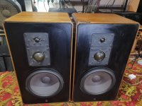
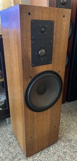
This will be a hybrid design with open-baffle speakers. I do have four Peerless SLS 8 (830667) left, which I hope to be able to use. One idea is to use two dual speakers per speaker, the other idea is to integrate 1 per speaker and build a sub out of the remaining two. But I haven’t checked if the spl would be sufficient for an open-baffle design. Since this is really in the early stages of research, feedback is very welcome!

I’m probably in way over my head with this as a first project but maaaaaaaybe there is a chance for me to actually get these things running 🙂 And even if this is a dead end, it was quite a fun journey so far.

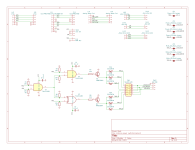
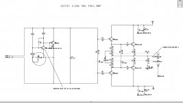
I have some drawings of the project attached.
ESL2.png


Where I am at the moment:

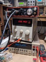
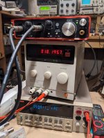
I started a first prototype based on some leftover 22mm wood, some FLRY-A 0,5mm2, 1,55mm OD cables and some harp pegs. I build a quick router jig and milled one vertical segment. constant wire distance as well as looping of the cables is achieved by some 3D-printed parts.

PXL_20250208_084431882.jpg


PXL_20250208_143931406.PORTRAIT.jpg


PXL_20250208_143943760.PORTRAIT.jpg


PXL_20250208_143950064.PORTRAIT.jpg


After having tensioned a first loop, things look promising, after 3 days under tension the wires are still as straight as they can be. I had some problems with the wire snapping at the top in the beginning, which is in my opinion mainly due to friction in the 3D-printed parts and the loops around the nails. I’ll have to redesign this part in order to allow the wire to distribute its tension over the whole length. But I’m optimistic that I’ll achieve this in the next try.

Attachments

Iron Schmitt phase inverter - lowest THD seen

Some recent measurements, show me a 2-3 triodes phase inverter with less than 0.0x% distortion, with more than 50Vrms on both outputs, with no feedback 🙂

Attachments

  • 2Vrms LR both.png
    2Vrms LR both.png
    50.2 KB · Views: 393
  • 20kHz.png
    20kHz.png
    53.2 KB · Views: 689
  • IS 2C51.png
    IS 2C51.png
    9.4 KB · Views: 735
  • PXL_20240107_123632776.jpg
    PXL_20240107_123632776.jpg
    383.8 KB · Views: 693
  • PXL_20240409_193342465.jpg
    PXL_20240409_193342465.jpg
    455.9 KB · Views: 378
  • PXL_20240409_193409626.jpg
    PXL_20240409_193409626.jpg
    437.3 KB · Views: 386

PCBs for Moving Coil RIAA preamplifier

I have one last pair of PCBs (shown in Photo) for the construction of a Moving Coil RIAA preamplifier as was presented in my article for Audioxpress (March 2014).
The price for both PCBs (two PCBs are needed for a stereo preamplifier) is 55 Euros plus shipping.
If you are interested, send me an e-mail at gntanavaras@gmail.com

Attachments

  • PCBs for RIAA preamplifier.jpg
    PCBs for RIAA preamplifier.jpg
    956.4 KB · Views: 2,145

Wire output to RCA sub input

Hello, I have an old 80s model jvc amplifier/ receiver and the only outputs it has on it are group one and two speaker wire outputs. The issue is, i just fixed an old klipsch subwoofer that i found on marketplace and the only input it has is RCA or Sub in. How do i go about connecting these two items together? Would connecting wire that has up to 60w running through it to an RCA input on a sub be harmful or would it even do anything?

Attachments

  • IMG_1983.jpeg
    IMG_1983.jpeg
    50.6 KB · Views: 27
  • IMG_1984.jpeg
    IMG_1984.jpeg
    571.3 KB · Views: 24

TH-4001 or A-290 horn for studio monitors?

Hello everyone.

I've been lurking on these forums for years. Currently in the process of designing no-compromise studio monitor system. It will be a 4-way looking something like this:

20-60Hz - 15" woofer (still deciding on the woofer)
60-600Hz TAD TL-1601b
600Hz - 8,000Hz TAD TD-4001
8,000Hz and up - RAAL ribbon

Looking for the best horn to make the most of the TD-4001 in those frequency ranges. Was recommended the Yuichi A-290, and can also get the TH-4001 clones made. Looking for the most transparent setup, and it will be driven with a high quality Linea Research DSP (gasp) and Benchmark / Bryston amps, so we have a lot of tools at our disposal, such as time alignment, FIR, linear phase EQ, etc.

Are there any other horn designs we should be looking at for this? Anything we may have overlooked?

Your help is much appreciated.

Vandersteen 2W subwoofer crossovers

I have owned a set of 2CeSignatures for several years; six months ago I purchased a Vandersteen Model 2W subwoofer on eBay. (Presumably, these two components should work well together.) There were no crossovers devices with the shipment (my mistake). A high-pass filter must be injected between the signal source (preamp) and the amplifier. The specifications of that filter are subject to a set of variables including the input impedance of the amplifier. At sale, Van supplied an adjustable crossover component (W-X2) that could be used to ear-test and determine the correct crossover device; once determined, the user could purchase a set of permanent filters form a Van distributor; and the W-X2 would no longer be necessary.

Lacking the W-2X, and using an online filter calculator, I built a few simple. cap/resistor filters using 50Hz cut-off, and random capacitance and resistance values (C/R values were set based on what I had sitting around; notice no input impedance is contained in that calculation.) Nothing worked, so I gave up and bought a W-X2 from a long time Van dealer ($140). Following instructions, I set the only adjustable (dip switch) value which was to be one level below the amp impedance; in my case, with a 50K Hz amp, the next lower value was 33Hz. Works fine, sounds good.

Assuming that 33Hz stays as the most pleasing level, I will have to find a dealer that carries a set of 30-40 year old filters marked "33." Why don't I just keep using the W-X2 and forget finding permanent filters? Per a short conversation with Richard Vandersteen, he told me to be sure to get permanent high-pass filters because the components in the W-X2 were crap and sounded like it. But, what would he know?

Anyway, this is a long lead up to this question: could anyone provide a schematic so I could build my own high-pass filters?

Distortion measurements for Audio Research SP-8 line-stage

I've been asking questions about tubes and capacitors and performance, where the answer always seems to involve "Does it meet specifications?". So, I figured I'd better check.

Tests were performed with a Scarlett Solo into a Mac Mini running Room EQ Wizard. Input voltage for all tests was ~1.76V

The high-frequency rolloff appears to be in the interface, as it appears in loopback measurements.

Frequency response
Manual States: +/- 0.25dB, 5Hz-30kHz
Result: 0.23dB total deviation, maximum to minimum (excluding high-frequency rolloff)

Distortion
Manual States: Less than 0.01% at 2V RMS output, 20Hz to 20kHz
Result: 0.007% THD maximum between 20Hz to 20kHz

Intermodulation Distortion
Manual States: Less than 0.002% at 2V RMS output
Result: 0.02% at 2V RMS output*
Note: Measurement was obtained using 7kHz and 13kHz twin-tone

--

I've included slides for the frequency and 2V distortion measurements. I've also included a 5v output static distortion slide for interest, although it is not relevant to any of the measurements discussed.

Thoughts: The frequency and distortion numbers seem to be inline with specifications. The IMD is high, but I don't understand the potential causes or ramifications of this enough to discuss it. For all measurements, I consider both my tools and techniques suspect, although I am making ever effort to be accurate, with the equipment I have. I allowed the amp to warm up for approximately 15 minutes before taking these measurements.

For full specifications: https://www.arcdb.ws/model/SP8

*Note: Slide for this measurement was lost

Attachments

  • SP-8 distortion.jpg
    SP-8 distortion.jpg
    248.9 KB · Views: 105
  • THD @ 5v.jpg
    THD @ 5v.jpg
    195.9 KB · Views: 100
  • Frequency response 1:2 dB scale.jpg
    Frequency response 1:2 dB scale.jpg
    127.4 KB · Views: 108

vFET / SIT data sheets

I know several V-FET / SIT data sheets have been posted over the years across many different threads, but I thought it'd be nice to have them all in one place.

Here's one fresh off the scanner - more to come when I have time to spare. Meanwhile, feel free to attach or link to whatever you have.

(Note to Mods: I hope posting these doesn't violate rule #9 - please delete the thread if you think otherwise. Thanks!)

Edit: I realize my file naming convention is not immediately obvious ==> the attached PDF contains 2SJ18, 2SK60, 2SK63 and 2SK79.

Attachments

Looking at Yuichi A-290 or TAD TH-4001 Clones: Makers

I haven't made a decision as of this time but I am planning on replacing my JBL 2380A horns with clones of either the Yuichi A-290 or TH-4001. The drivers in use are Radian Neo 950 FB / 16. (Recent upgrade from JBL2440)

Athos for either A-290 or TH-4001:

AthosAudio - Passionate about wood and sound

They also sell on eBay and have a good buyers rating. Located in Hungary shipping is a bit pricey, but manageable.

MAKA for Yuichi A-290:

Homepage - MAKA Precision Horns

Located in Holland, likely a bit quicker and a little less expensive to ship.

I've heard of both, have no direct experience with either.

WTB 2200uF 16v United Chemicon Polymer APSG160ELL222MJ + 4700UF 35V United Chemicon EGPD350ELL472MK30H

I'm currently trying my hand at a USSA5 amplifier and need a few more exotic capacitors. Does anyone have at least four of each of these in his drawer and want some space for new parts and some cash?
What I'm looking for:
2200uF 16v United Chemicon Polymer APSG160ELL222MJ or RNL1C222MDS1 and
4700UF 35V United Chemicon EGPD350ELL472MK30H or EKYB350ELL472MM or UKW1V472MHD
-min. four pieces each

And yes, I know that some of these types are still available from some retailers, but ordering a handful of components from them always involves astronomical shipping costs—so I'm asking you first.

Thanks for checking!

Magnet Amplifier (new info)

I read about this a long time ago. Development in amplification didn't jump from vacuum tube then to the transistor, there was something in the middle......the magnetic amplifier.

WWII Germany perfected the device, and I read that one of their V-2 rockets crashed in England and didn't explode. When it was salvaged and analyzed the scientists there pieced together a magnetic amplifier used in its construction.

I have a couple of books on them, and I heard that it could be used to amplify sound. I did a quick search before making this thread and the subject is a little dead.

Just today I found this awesome site:
Homemade Magnetic Audio Amplifier.

http://sparkbangbuzz.com/mag-amp/mag-amp.htm

This is a tantalizing bit from the first site I listed site:
"The mag amp is true amplification without the use of tubes, transistors or IC's but it does require the use of an AC power source. While most ac oscillators require the use of transistors, this amp could conceivably run using an AC power signal from a carbon arc or maybe even a zinc oscillator or similar."

I wonder if the experts here could build on this and make something really well performing.

I hope somebody is interested in this stuff as much as I am, it looks neat.
Projects by fanatics, for fanatics
Get answers and advice for everyone wanting to learn the art of audio.
Join the Community
507,811
Members
7,889,418
Messages

Filter

Forum Statistics

Threads
406,297
Messages
7,889,418
Members
507,811
Latest member
Cystore