Hello there,
So, trying to further develop my Mickey Mouse amp.
Next step would be this, putting a CCS load on the output tubes.
Topology is very simple, 2 amplification stages through a 6sn7 (china amp) and a cathode biased 300b (450V, 70V at cathode, 220uf and 1k at the cathode).
Looked the whole internet for a schematic, went through Bartoli and other websites (he uses curators mainly for driver stage) but couldn't find anything ready?
Would someone be so kind?
Ps. The schematic is the plain vanilla one, many things have been changed/optimized, but the output stage.
Attachments
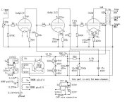

The plate of the output tube will swing from near zero to near TWICE the B+ voltage in normal operation. You can put a CCS on the output tube, but you would need to connect it to a power supply of about twice the voltage that you would use with a transformer in the plate circuit. You would put the CCS where the transformer primary is not and parafeed the transformer with a capacitor in series with the transformer. In this arrangement the other end of the transformer primary is often returned to the cathode of the output tube.
I did this with a 45 tube CCS loaded from a 500 volt supply to use as a driver for an 845 tube. There was no transformer at all. In either case the CCS will be dissipating about the same amount of power as the output tube. That alone probably makes it a non starter for a 300B. It took a good size heat sink (two CCSs) for a pair of 45s that were dissipating about 5 watts each.
I noticed your second post while I was typing mine. You could simply use a parafeed choke and transformer set to accomplish the same result. In either case there is no DC current flowing through the transformer primary, so no gap is needed or wanted.
A 400-0-400V primary, tube rectifier, cap input filter, and 80mA load will give you about 460V B+.
Your electrolytic caps are only 450V.
I am talking about the caps that are after the choke.
An unloaded supply has the same DC voltage on both sides of the choke.
Those indirect heated cathodes warm up slowly, so the B+ after the series resistor can also rise along with all the other caps.
You might want to use 500V caps after the choke.
Do not forget to check the B+ voltage while the output tubes warm up; it might get close to 500V.
- Home
- Amplifiers
- Tubes / Valves
- Some schematic of 300b SET with anode loaded CCS?