New Headphone Day

I’ve never had a set of ”hifi“ headphones. The nicest set I ever had was the $20 in ears I got for my phone because I also needed them to have a mic. I’m not an audiophile, I have never auditioned any headphones, I wouldn’t call myself a critical listener.

After completing @alexcp omicron headphone amp, I decided to get some nice headphones, Grado SR225x. They sound great, pretty comfortable (without glasses) and seem reasonably priced. My music is a lot of classic rock, acoustic guitar and some 80s alternative.
  • Like
Reactions: alexcp

Box dimensions search with room modes

Hi there!

I've been using this to brute-force speaker box dimensions. Wondering if somebody else does this as well. If you play with it, please let me know what you think or what bugs you see.

What it does:
  • Grid search for box dimensions in X, Y and Z.
  • Compute volume and check if it's between the allowed tolerance
  • Compute the modes inside of the box
  • Use least squares to rank, using the distance between modes up to a limit frequency. Trying to distribute the modes rather than doing a global optimization. I found it was better. Many ways to do this.
It usually ranks well measurements with prime numbers or relative primes.

You can try it here: https://zsum.net/box_search/

1707607977809.png


Regards.
  • Like
Reactions: krevilplays and GM

static hiss at 0 volume that diminishes as I increase volume - no input

So, I just recapped, new tubed and adjusted balance and bias. Also did 2 dexoit sessions on the pins and sockets of tubes and all wipers and switches. At the 0 volume there is this white noiseish coming through the speakers and as I turn up the volume and at max (with nothing playing) it actually goes mostly away but is very faint. When music is playing I cannot hear it, just when there is no signal. Inserting shirted RCA plugs has no affect neither does changing to any other inputs or selections on the Stereo, mono, L, R.

It is a beautiful amp, very pleased with how it has turned out so far and would love to determine if this is normal (doubt it) or there are some usual players I can look at.

More cleaning? Maybe check other components along signal path? Ground? Any suggestions, thank you!

Attachments

  • IMG_1197.jpeg
    IMG_1197.jpeg
    474.3 KB · Views: 87

CD Player Laser Diode Current Voltage and Power

Hallo

See data sheet. I have a few questions about Laser Power, current and voltage. Example calculation: If I Calculate Laser current x Laser Voltage = 50mA x 2V = 100mW Where is the Calculation Error? Laser diode has a maximum power P = 5mW. What Voltage and Current is present at the Laser Diode?

So Power loss is around 100mW? Why isn't Power loss listed in the Data sheet?

What does Monitor Current mean in the Data Sheet?

Gruss Chris

Attachments

Hiraga Class A Build Question

Hello audio geeks

I won this incomplete build in an auction. I was going to complete it however wanted to first confirm before firing it up:

  • This build uses high current 24V SMPS, is an SMPS suitable for this build?
  • If the above is the case, I could consider a DIY Audio Store SMPS filter kit to block any conversion noise?
  • Otherwise, a conventional PS is better?
  • Is existing heatsinking likely to be OK, or inadequate? This is class A after all......

Keen for your thoughts. I can use the case for another build if this is likely to be a no-go.

Thanks all!

Attachments

  • IMG_1073.jpg
    IMG_1073.jpg
    541.5 KB · Views: 176
  • IMG_1074.jpg
    IMG_1074.jpg
    466.7 KB · Views: 182
  • IMG_1075.jpg
    IMG_1075.jpg
    375.6 KB · Views: 171

The amplifier does not turn on, the mosFETs get extremely hot. There may also be missing pieces in the solution. Or they may have moved. We can't see.

Amplifier models overheat. When you give power it gives 12 volts. And. It works on red, the green light is not on. We couldn't figure it out. 23 people looked at it before us, the masters looked at it. But we are trying to deal with it somehow. We couldn't get the green light to work and I couldn't get it to work. Can you help us with this? Respects.
20240119_212557.jpg
20240113_194223.jpg
20240119_211546.jpg
20240119_234312.jpg

Tweeter and Cap, Theoretical Speculation

As I start to work out a crossover upgrade for my ER18RNX/27TDFC, I've been considering cap upgrades for the tweeter and this looks interesting.

The speaker is good, the 27TDFC is good (way better than its price point might suggest), so a good cap e.g. alumen Z cap looks appropriate.
But what about a Jantzen Amber Zcap? Results could be spectacular.

But the cost of that cap would buy a better tweeter such as SEAS Crescendo, which Troels likes a whole lot and would appear to be usefully better than the 27TDFC.

So it make me wonder, if spending one way or the other, which mix would be best;
27TFC and Amber Z cap
Crescendo and a more basic cap like Claritycap CMR

All very theoretical but perhaps an interesting poser?

Phase check

Hello everyone. Hope you are all well.

I have something like an integrated amp that I am working on, and I would like to be able to check that I have not accidentally inverted any channels due to haphazard or simply ignorant wiring. What would be the best way to make sure that everything stays + and - from pre-amp inputs to amp outputs?

I don't think a "battery test" at pre-amp inputs will work since I know for sure there are coupling capacitors at pre-amp inputs.

Also, it will be extremely inconvenient for me to procure an oscilloscope, sadly.

Academy Audio VCU Muses volume control plus mini dual supply

Never really got round to using this properly as I went to a balanced source, so in as new condition and working order. The Muses is simply the best volume control available, no question.

Included is a complete mini dual polarity 15V 78xx / 79xx regulated supply module designed for me by the mighty Prasi. The built module requires dual secondaries so I will include a second improved PCB that will accommodate both dual and centre tapped windings. A BOM will be provided should the buyer need to build the second supply.

Also included is a 230V AC, 15 + 15V 2VA Myrra transformer with AMB mounting PCB - a whole solution ready to go. If the buyer wanted fancy low noise regulation, then build the green PCB up with 18V regs and strap some 15V LDOVR regs on the output.

For USA this PCB transformer should work.

The VCU has ben replaced by the VCX, so possibly a collectors item 😉

I highly recommend the VCU has buffers on the input or output depending on your source and end circuit impedance etc. Sjostrom Diamond buffers are superb but XRKAudio has developed some very good ones available in his Etsy shop:
https://www.etsy.com/uk/listing/1619024473/diamond-buffer-by-jhofland?ref=cart

SOLD

IMG_0553.JPG
SOLD

Pink Triangle Anniversary PSU

Hello everyone,

I'm working on a Pink Triangle Anniversary PSU, I can't find schematics or any info on the design on this so its a bit difficult for me to fully understand its workings.

The PSU switches on but it drives the motor into runaway speed. The issue started after the 12V batteries have been replaced with new ones. This is for both 33 and 45 rpm.

My understanding of how the PSU should work is:

Mains supply power to the electronics inside the PSU, the motor is driven from the big 12V (6+6) batteries and the speed control is achieved by the AC tacho attached to the DC motor.
I did check the motor separetly and suppling different DC voltages results in variation in the AC feedback so I belive the motor itself is operating correctly.

I'm able to track the AC feedback signal through the initial quad op-amp, it gets amplified and then it goes through a pair(NPN, PNP) of medium power transistors BD135 and BD136 and then it gets complicated for me as there is a comparator circuit (LM393N) two logic chips (MM74HC00N, MM74HC02N ) and a precision timer/oscillator chip (ZN1034E). All the chips have 5V supply present at Vcc pins. The basis of the NPN transistor seems to be came the signal output of the logic chip MM74HC00N.

I have changed the ZN1034 and the MM74HC00N. The transistor right of MM74HC00N is a BC639 NPN.

The C of printed circuit board goes to the left relay.
I have replaced the precision timer chip however the issue remains, all the trimpots seems to be working fine. PSU is fully recapped.
Is there anyone who can send a schematic of the anniversary psu?

Thank you very much for your help

Unorthodoxy - a Wharfedale W90D odyssey

If I can channel my inner Great Carnac, I’d say the answer to my question would be to unload the W90Ds and just build a proven DIY design. But I’ll don my fire-rated garments and ask anyway…forgive me if this offends anyone.

I’ve had these W90D speakers for several years and have made several attempts to bring them up to par. I’ve seen many comments about how easy and pleasant sounding the Wharfedales of this era are but these have never done much for me. I’ve tried the SX-780, my Denon AVR-3000 and currently a Kenwood Basic M1A in various settings and nary a positive twitch. My hand-me-down A25s (in comparison) sound just like many describe: perfect to listen to all day even without the highs and lows. And yes, the A26 or related alternate designs are on my radar.

I’ve got the original purple egg tweeters, but one had the broken Al lead so I pulled them and dropped in some Visatons. I also replaced all caps with the Dayton PMPC precision series and most recently grafted new L-pads. The crossovers still have the original autoformer and iron core inductor.

My build experience is limited: small bookshelf full rangers with Alpair 10P units. I like these.

Also, I’m working on the LX-Mini (no sub); bought the kit from Madisound and working out the assembly/construction.

But back to the W90D. These are the single cavity design with standard (not Alnico) woofers. It would seem from all the modern “Kate Moss” like designs (tall and skinny), the horizontal side by side layout is out of fashion.

Is there ANY potential to use the W90 cabs/enclosure with updated xo and drivers to make these worthwhile?

Full disclosure, I would exercise every option to be able to revert back to stock - for some reason I can’t adulterate a pair in decent shape. But I’m willing to exercise my CNC router to make the most of it.

I did try to offload these a while back but seems few had interest.

Ok, ready for the flames…..

Z

Are 'bad caps' still a thing?

I'm referring here to the capacitor plague era and premature failures, NOT sound quality.

The reason I ask is because yesterday I went over the 'lytic caps inside the PSU (SMPS) of an an approx. 10 year old Marantz UD7007 with an ESR-meter.
They all measured fine despite the fact that these were mostly no-name brands of Chinese make.
We're talking brands such as ZHN, KSD, Jicon, Lelon and TK (supposedly Japanese brand Toshin Kogyo). Of the latter, many of the fancier looking ones in the analogue board and some in the PSU were rebranded D & M (Denon & Marantz?). Only the Lelon brand was already familiar to me.

All measured fine, including the low-ESR types which would be the first to suffer problems.

Has the time come that we could say Chinese caps deserve a better reputation?

P1030532.JPG

Audison SRx 4

Hello,
I'm trying to remove the pcb from the housing of Audison SRx 4. The top cover (silver) holds the clamps of the transitors, but is very tight fitted to the blue part.. Is there a normal way to remove this..??? ..don't want to use brute force.

Attachments

  • SRx 41.jpg
    SRx 41.jpg
    84.4 KB · Views: 85
  • SRx 42.jpg
    SRx 42.jpg
    92.3 KB · Views: 90
  • SRx 43.jpg
    SRx 43.jpg
    112.8 KB · Views: 77
  • SRx 44.jpg
    SRx 44.jpg
    81.1 KB · Views: 87

Hifonics BXL2000D protection circuit issues

Long story short.
The amplifier powers up normally but the relay doesn't engage, the pin for it at the PS board is tied to q2, q3, q4. These have been swapped before me, all being npn which is odd, doesn't seem right. At least one should be pnp to pull to ground !? It's not the the relay itself, it works, tried it outside of the board. There is a 1n4148 diode between the relay and the PS board, changing this one did not do anything.

Does anyone know what they should be ? Q2, Q3 and Q4 ?

The other issue is the IRS 21844s is in shutdown mode (SD ~ 0.3v). Removing 2SD1302 on the main board, makes the amp play as it should. I've rebuild the DWM3640, was even able to source the MAX transistor...but i still get shutdown mode.

I've checked the voltage +-5v, +12v, +15 everything is fine...
PROT pin on the PS board is sitting at 1v, Not sure if this has to be 15v ?

Attachments

  • 1.jpg
    1.jpg
    923.4 KB · Views: 123
  • 2.jpg
    2.jpg
    482.3 KB · Views: 137
  • 3.jpg
    3.jpg
    614.4 KB · Views: 111

Hifonics Maxximus X4 protect

Working on a Hifonics Maxximus X4 2 channel class D, two boards in one housing. When switching on, it goes directly in protect, with very low inrush current.
When I quick "pulse" the remote of the power supply for about one minute , I got about +/-30V rail voltage. Inrush current about 1A. Power on and protect led is flashing.
Mosfets both boards PS and amplifier are OK.

I sustpect the protection itself, but I'm not familiar with the boards used.. some pics of the boards and PS driverboard. If there are schematics available for this amp or similar ones, that would be a great help for me.

hifonics_maxximus_x4_0.jpghifonics_maxximus_x4_0a.jpghifonics_maxximus_x4_1.jpghifonics_maxximus_x4_2.jpghifonics_maxximus_x4_3.jpghifonics_maxximus_x4_4.jpghifonics_maxximus_x4_5.jpg.

The elusive pin 13 (TEST) on the SAA7220?

Alright, which one of you brave lads has done the unthinkable and hooked pin 13, TEST, on a SAA7220 to VCC? Nowhere in the datasheet is there any mention of the function of this pin, other than it being pulled low internally? What happens when you hook it to VCC? Did anyone try? Or is this, a good 35 years to date, still unchartered territory? Should I venture there, and risk being pulled into a quantum time vortex and be transported back to Philips' Natlab in the mid 1980's?

pin13_saa7220.jpg

DIY full range OB

Hi all,

I'm considering to build a DIY OB using a full range driver together with one or two Peerless SLS 315 (12 inch) drivers per channel. I already own 4 Peerless SLS 12 drivers in total and I'm wondering if these would make a good OB canditate together with a 6 to 8 inch full range driver?

For instance a TangBand W8-2145, or a Lii audio Silver-8 driver. The latter has a rather low Qts by the way, not sure if that would suit a OB, although I've seen this driver in an OB configuration.

Experiences with Sica drivers?

Hi,

While looking for a 10" or 12" driver, I stumbled upon Sica drivers.

They can be had for very decent prices in a UK shop (hotrox) and look very well built with good specs.......but nobody seems to be using them which makes me suspicious right off the bat. no reviews, builds, ... It comes from the Jensen factory.

I was thinking about using 2 12" woofers, only 80GBP (about 100eur) each, in parallel so it' a 4Ohm load and active DSP with my minidsp 2x4HD. It's for a home application, crossed over at 800Hz to a CD.

https://en.toutlehautparleur.com/media/catalog/product/datasheet/sica/Z007831.pdf

It looks decently flat until 1.5 Khz in a ported enclosure of only 45L which would be very convenient, would cross them over at 800Hz to a CD with a 2nd or 3rd order.

Anybody any opinions on these? Would they best an equally cheap SB Audience 12MW200 or other middbass drivers?

Thanks!

Denon PRA-1500 input selector problem fixed

Just in case somebody else has the same problem: I fixed my Denon PRA-1500 input selector instability problem, and here is a short how-to:

Symptoms: after turning on the PRA-1500 the input selector switch (button operated) lost its memory, making it necessary to press the desired selection setting again and again. The problem went away after some time while the preamp was warming up.

Diagnosis: the preamp is built around a Toshiba TC9152P analog function switch. The TC9152P features an 'ALL_OFF' input with positive logic, which is connected in the schematic to a monostable operated by VDD. Any glitch on VDD higher than 0.8V will trigger a pulse on the ALL_OFF input, which causes the TC9152P to go into a 'no select' mode.

Solution: replacement of electrolytic capacitors in the power supply section did not solve the VDD glitch problem. Finally I found that the 18V linear regulator IC14 (NJM78M18FA) produced the glitches. A very expensive and sturdy looking TO220 part, but probaly a bad design. I replaced it with a 2A L78S18CV equivalent from ST Micro. And I did replace the -18V counterpart NJM79M18FA with an ON semi equivalent for good measure.

X-Over with UbuntuStudio, Pipewire and Calf

Since 2015 I run 24/7 a PC with KX-Studio which provides me the following services:
Everything runs in principle flawlessly. And although they say "Never change a running system" I wanted to try something new since KX-Studio is no longer developed. Most new distributions use PIPEWIRE as sound server. As distribution I chose Ubuntu Studio 23.04. Everything should be as easy as possible to set up and use via GUIs without cryptic command lines. For this I wanted to use the really great CALF plugins, especially the 4 band crossover. The sound is output via 4x2 channel HDMI, of which I only use 6 channels. As an amplifier I continue to use an HDMI AV receiver. I have in the meantime instead of the Onkyo TX-SR605 bought an ONKYO TX-SR876. There are used already for under 100 Euro.

And I must say I am inspired by the result. But everything in turn. I concentrate here on the settings for the crossover.
1. Installing Ubuntu Studio 23.04 should be possible for everyone. There are enough instructions
2. I install the following programs or they are already installed:
--- raysession
--- wireplumber
--- qpwgraph
--- calf-plugins
--- mc
--- ssh
--- agordejo
--- synaptic
--- flatpak
--- clementine
with flatpak additionally
--- coppwr
--- Simple Wireplumber GUI
--- Helvum

--- from WEB Universal Media Server

3. set all playback devices to "Pro Audio" in the audio - system settings

alle-wiedergabegeraete-auf-quotpro-audioquot-einstellen-in-den-audio-systemeinstellungen_1224851.png


4. start RaySession, create new session, add Calf Jack Host as applicant

raysession_1224852.png


5. load "X-Over 4 Band" in Calf Host

calf-4-band-x-over_1224855.png


6. open X-Over and define the frequency bands. For the Quadral I choose180 / 3800 and quite steep LR8.

frequenzbaender_1224856.png


7. do the virtual "wiring" in RaySession.
--- In this example Firefox outputs the sound over my USB interface AND over the chain crossover->HDMI->AVReceiver->speakers.

beispiel-quotverkabelungquot_1224870.png


--- Any "cabling" can be realized with different programs (here Firefox, VLC, Clementine). All my outputs are wired to the crossover AND the USB interface (for my headphones).

weitere-verbindungen_1224872.png


8. also a BT connection to my cell phone is possible and works wonderfully.

verbindung-ueber-bt-mit-handy_1224874.png


9. finally save the setup. All settings (including the settings in Calf) are saved and can be loaded again.

speichern_1224876.png


10. in qpwgraph the whole thing looks similar. But I didn't manage to load CALF with it.

qwpgraph_1224877.png


11. here are the views from coppwr. Here you can get a lot of additional information.

coppwr_1224878.png


coppwr_1224879.png


Maybe someone is interested.

BR
Guenter

Attachments

  • beispiel-quotverkabelungquot_1224870.png
    beispiel-quotverkabelungquot_1224870.png
    152.5 KB · Views: 138
  • calf-4-band-x-over_1224855.png
    calf-4-band-x-over_1224855.png
    131.3 KB · Views: 148

Idiosycratic Amplifier Design Performance

I'm very interested in getting the forum expert's technical critique of this IMO slightly unusual high end production amplifier from the late 90's. Design highlights are as follows. High bias (class A likely close to 10 watts), high power bandwidth to 150khz, high input impedance at 150K, doubles power output from 8 to 4 ohms, low 6db feedback, and is absolutely stable with no output filtering network. The amp also has 130,000uf of overall power supply filtering.

Q15 & 16 in the servo circuit is the only issue I find, in that they require tight matching otherwise audible 60hz hum is introduced.

Though it may not measure impressively well with regards to THD and IM distortion, this is one of the most dynamic and musical 100 watt A/B amplifiers I have ever heard. Presenting a big easy sound that is never harsh, while still being wonderfully transparent and detailed. All this in a well built compact (37 pound) all aluminum chassis.

Thoughts?

123.jpg

For Sale NIB Tango NY-15-3.5S Output Transformer Hirata Electric Corp

Spec Sheet.jpgTango Boxes.jpg

Offering a pair of New in the Box single ended audio output transformers. Complete with original documentation and metal “Tango” plates. One transformer was removed, but left in its plastic wrap, for photo. These are the top of the line original Hirata Tango transformers with Permalloy Core. 45% Nickel Primary. Virtually unobtainable now.

Asking $2750. Buyer to pay all shipping costs.


Specs:
Impedance Primary 3.5 K Ohms
Secondary 0-4-8-16 Ohms
Power 15 Watts (30Hz)
Frequency Response 20Hz-45Hz (-2dB, 4v, rp=zp, Ib=90mA)
Primary Inductance Min. 23H (1mW), Max 30H (50Hz, Ib=90A)
Max DC current 200mA Loss 0.41dB (16 Ohms)
Primary DC Resistance 115 Ohms
Dimensions W110mm D110mm H114mm Weight 4.5 kg
Color Hammer Tone Grey

Attachments

  • Plate.jpg
    Plate.jpg
    287.6 KB · Views: 139
  • Tag.jpg
    Tag.jpg
    229.5 KB · Views: 157

Powerful full range speakers?

Looking to build a pair of stereo speakers. I need something with a difference though and don't know where to start with drivers and config, so will present a list of what I need from this speaker

Based on max 6.5" drivers so that I can fit the build on my equipment. A larger driver will increase panel width in excess of the CNC/laser work bed
High fidelity monitor grade
Must be single FR or coax type, not multi driver multiway
Have drivers on the front and back of the box with good presentation at about 2-6m on both firing sides
120wrms @ 8R available per channel

I am in AU, so driver availability is an issue. Should I try a PA driver like the Faitalpros? A very brash PA type sound would not be the sound that I am looking for. Maybe more like these Tannoys but 90 would be a good SPL target

BJT transistor matching requirements for various circuit blocks

Hello,

Just finished sweeping through more than 200 BJTs for my MC/MM phono preamp, measuring Hfe and Is indirectly through Vbe (with base/collector tied) using diode test function of a DVM. A bit of a PITA if you ask me, but you gotta do what you gotta do right? Or do we? Throughout this endeavor I couldn't help but wondering, does any audio manufacturer goes through this trouble ? Still have 200 more of the BC549/BC556 to measure... 😡

Thank god for spreadsheets, I can sort the data set by Hfe then Vbe or inversely in order to get the matches. I also produced statistics from the 2SC2547D/2SA1085D data and right off the bat I can tell you I can't get beta matching for the two polarities out of 50 NPN and 100 PNP for the input transistors. I read here that this is normal for the epitaxial transistors.

Descriptive statistics also put forward the following properties:

1. Hfe is generally higher for NPN than PNP, even if they belong to the same beta group ("D" suffix);
2. Hfe varies much more than Vbe regardless of polarity;
3. Hfe variance is much higher for NPN than PNP (300.2 vs 47.8)
4. Vbe variance is also higher for NPN than PNP (1.75 vs 0.81), but less variable than Hfe like mentioned in point 2;
5. In my sample, PNPs have Hfe range lower than specified in the datasheet... Bad batch, bad luck, fakes ????

That being said, I'm wondering what to aim for in different parts of the circuit (see below), keeping in mind that beta match may be impossible between polarities. I know that:
  • The parallel transistors of the input cascode need to be matched for Is; that is have the same collector current for a given Vbe for equal current sharing between them;
  • Each leg of a long-tailed pair should be matched in beta.
The outstanding points:
  • By which parameter to match the cascode's top transistors?
  • Hfe influences the device's dynamic emitter resistance (re), but when emitter degeneration resistors (Re) are present, Hfe matching is more relaxed. So do I need to place the closest beta matches where the re/Re ratio is highest, e.g. where the degeneration resistor has the least effect on total output impedance?
  • Do the CCS transistors need to be matched from one rail to the other? Matched for which parameter?
  • Do the current buffer transistors (discrete Darlington configuration) need to be matched, and if yes by which parameter, total Darlington combined gain from rail to rail? I feel these positions are less critical since gain will be high anyways...
  • The long-tailed pairs input devices should be matched in beta, but that is for the lowest input transistor since the LTPs are implemented as a cascode. The top transistors are tied by their bases, should they be matched for Is like the input parallel trios?
I know that's a lot of questions, I don't expect all be necessary answered. I am really a newbie in all this and will appreciate any help!
- Joris

1707153139157.png

Group buy: DCT03 DC trap (filter) for toroidal transformers

I have made a bigger DC filter for getting rid of the hum in big toroidal transformers. The pcb has 105 um copper and more than 1 cm wide traces. If the interest is big enough I will go ahead with a group buy. The diode package can handle 12 amps and 68000 uF/16 V caps will fit. This pcb is perfect for those who like it big.

Attachments

  • dct03_built.jpg
    dct03_built.jpg
    144.3 KB · Views: 3,776

Grooveshop DIY

Hello all
Today I am starting on a small home workshop/studio build log. I am semi retired and moved into an old "tiny home" in QLD. I have had a workshop in the shed, but the heat makes it very uncomfortable and a lot of projects waiting in queue. This place has two bedrooms. We use the larger one for home studio as well. I am going to give the room a total makeover and install an electronics and craft workbench in one corner. A music and 3D modelling studio two one side in a recessed area

This is the corner that the workshop will occupy. The condition of this old place is fairly bad, going to need a lot of TLC

IMG_5797.JPEG

Updated Storm Shadow for Pluvia 7.2

Before Christmas, there was talk of a possible updated Storm Shadow for the Pluvia 7.2

I don't like to ask for updates for free work, but I need to decide to move on to something else.

I've really enjoyed my Lance speakers but want to get into a little bigger driver/enclosure and after 5 years, just ready for something different.

I don't think the FF105wk will be enough of an upgrade, more a side grade for going only a little lower, and my budget reaches above the CHN-70 but I'm open to hearing the opinion on the Skyflash as a bigger brother to the Lance.

Side note: I tried some fairly expensive powered 2-way speakers. For my use case, close and low volume, I'm sold on the advantages of full range.

DHT driver for triode wired SE EL84, 6V6 or EL34

Hello All.

I have a question regarding the use of DHTs as driver tubes for triode wired pentodes in a single ended amp. I have had a look online, but have not found anything about this topic. Why is this the case? Are DHTs unsuitable as drivers in this case?

If a DHT is able to properly drive a pentode wired as a triode, wouldn't the goodness of the DHT driver come through if that power tube was properly driven?

I have a reasonably good stash of 01A, 26, 71A, 30, and 31 tubes (and dozens of IDHT 27s), and I'm looking to build a small amp for use with the HF section of my horn two way speakers. The amp would do 500 HZ and up and would not require more that 2 watts of output. I can't find a single schematic that uses a DHT in the driver position, and a triode wired pentode in the power tube position.

Thanks in advance for your input on this.

SG3525 dead time issue?

Using the SG3525 in single-ended mode. Everything seems fine, but the longer the output is on, the more power supply current is demanded, and the IC gets hot pretty quick. The gate driver and IGBT is totally fine, the issue is excessive power supply current drawn by the SG3525.
Is this a dead time issue? I thought this would only be a problem in push pull, and I could set the RD to 0 ohms in single ended operation.

Attachments

Marshall 8040 Valvestate repair

Repairing my daughters amp ready for sale.
It worked several years ago when put away in the loft.

Now:
Power up, either nothing or it powers up.
Example, on the bench, plugged in to measure DC volts at smoothing caps - nothing.
Unplugged while considering what to check next.
Plugged back in to measure transformer AC at board.
Did nothing else, nothing moved, no switch operated. Only plugged in to wall.
Power on plop from speaker, hum, we have power.

This is likely not be the only fault.
Before dismantling I had sound from boost channel but nothing from clean channel.
Boost channel was much quieter than it should be.

I have seen a suggestion to reflow solder joints as allegedly these amps used early lead free solder that is susceptible to failure.

Question, joints look ok to me.
Are there visible signs of failed solder joints or should I go ahead and reflow them all regardless?

KEF coaxial SP1596 tweeter teardown and fix, need 39mm diaphragm!

Sorry for the long thread title but hopefully gets to the point.

I've wanted to try a Kef coax for a while, especially the later 'tangerine' waveguide versions just because they look so nice!

Bought these recently. They are the 8". I really wanted the 5 but these will probably be used naked and not knowing the FS or qts, maybe the 8 will be a better bet for reaching low enough without box loading.

Anyway the chap I bought the (bare) 8" from gave me the tweeters as they were not functioning. This was great as I really like the look of these things and so I've made a start taking them to bits to see what has happened to them and if they can be mended.

So they measure open circuit unsurprisingly. I tried to unscrew the second black piece on the back to no avail so I started at the tangerine end. Cut through some glue and finally it prised off.
IMG20230716104942.jpg

Then it was obvious where in the VC the failure was. The dome would hang from the one remaining wire! Looks like it has burned through .
IMG20230716105046.jpg

Then I picked away at the black piece around the diaphragm and now have a blank sheet for repairing . Been looking for 39mm aluminium domes but not found anything suitable yet. Found these on AliExpress I might take a punt on. Obviously I will have to measure everything but I was planning on a custom XO anyway.

https://a.aliexpress.com/_Ew7pKpp

https://a.aliexpress.com/_EwfbyKF

The wires that run all the way through to connect to the back of the main driver are not part of the VC but extensions of thicker guage enamelled wire that the VC soldered to. It was here that the failure occurred.

IMG20230716120019.jpg

Shall keep the thread updated with progress.

Anyone know of any 39mm aluminium domes?
  • Like
Reactions: Juhazi

Will this 12DC relay work for my situation?

I want to use the 12v trigger outlet on my Denon X3800 AV receiver to turn on/turn off a small AC Infinity brand S6
Aircon fan. The fan has a wall wart AC adapter that plugs into 120v and outputs.43A. The fan uses 5 watts.
Here's the relay.. https://a.co/d/ cBCG37K Can't I splice the "normally open" leads into one of the wires on a 1 ft, 120v extension cable that the wall wart adapter is plugged into and the 12v trigger from the AV receiver into the 12v side of the device so it turns the fan on and off?

My first attempt with a concrete baffle

The mold is made of 3mm PVC foam. I scored it about 2mm deep, folded it into shape and glued it with super glue. The edges are reinforced with foam strips. Without these, the mold would bend outward. I used wire mesh as reinforcement in the critical areas. The threaded sleeves are fixed with screws through the bottom of the mold. Due to their shape, they cannot twist and by the bolted shims they cannot be pulled out of the concrete.

I placed the mold on a board with screws attached vertically in all four corners. By adjusting the screws and using a spirit level, I aligned the mold horizontally.

The inserts for the speaker drivers are made of styrofoam, cut into shape with a DIY hot wire styrofoam cutter.

I brushed the mold and the inserts for the speaker drivers very sparingly with olive oil as a release agent.

The concrete is actually liquid screed. I mixed the screed according to instructions and poured it in one pass. Air bubbles escape by themselves. Curing takes only one day. Result: It works as intended. The screed becomes rock hard, has a very smooth surface and does not shrink.

Attachments

  • 1.jpg
    1.jpg
    87.4 KB · Views: 331
  • 2.jpg
    2.jpg
    90 KB · Views: 323
  • 3.jpg
    3.jpg
    75.5 KB · Views: 315
  • 4.jpg
    4.jpg
    100.4 KB · Views: 351
  • 5.jpg
    5.jpg
    104.3 KB · Views: 357
  • 6.jpg
    6.jpg
    99.8 KB · Views: 352
  • 7.jpg
    7.jpg
    89.2 KB · Views: 357

DC Filter against humming Toroidals - Summary of the most interesting Comments

DC filter - summary of the most interesting comments here on diyaudio - all mentioned post-# from
http://www.diyaudio.com/forums/solid-state/2080-dc-filter.html
unless otherwise stated:

Basic Descriptions
Theory of Operation (very good explanation): post #20+25+200+199+235
and post #32 about
http://www.diyaudio.com/forums/powe...buzzing-toroid-transformers-what-right-4.html
and post #50 about
http://www.diyaudio.com/forums/power-supplies/104626-dc-blocking-filter-mains-5.html
and post #51 about
http://www.diyaudio.com/forums/powe...buzzing-toroid-transformers-what-right-6.html

white paper of Plitron (11. February 2002) post #38#155#157#226#240 (last URL) and post #76 about
http://www.diyaudio.com/forums/powe...buzzing-toroid-transformers-what-right-8.html

Measurements/Experiments
Measurement (oscillogram pics) from EVA 50mV DC, heater in half-power mode (unfortunately deleted) post #57 + comment post #119 and post #21+26 about
http://www.diyaudio.com/forums/solid-state/37942-diy-ps-audio-humbuster-3.html
and post #39 about
http://www.diyaudio.com/forums/powe...buzzing-toroid-transformers-what-right-5.html
DC measurings by post #116 about
http://www.diyaudio.com/forums/power-supplies/104626-dc-blocking-filter-mains-12.html
and post #30 about
http://www.diyaudio.com/forums/power-supplies/104626-dc-blocking-filter-mains-3.html
simulation by post #51 about
http://www.diyaudio.com/forums/power-supplies/104626-dc-blocking-filter-mains-6.html

Current through Capacitor - minimum requirements
Low Voltage capacitors in most cases low current capacitors (EVA) post #73
advice for sufficient current capacity post #18
calculate appropriate numbers for the capacitor value post #134-140 and post #23 about
http://www.diyaudio.com/forums/power-supplies/104626-dc-blocking-filter-mains-3.html

Circuit Topologies
Electrolytic Capacitors: connected in parallel (but anti-phase) vs. serial connection "back to back": post #124+125+132+215+216+227 and post #108+83 about
http://www.diyaudio.com/forums/power-supplies/104626-dc-blocking-filter-mains-11.html
and post 43+46 about
http://www.diyaudio.com/forums/power-supplies/104626-dc-blocking-filter-mains-5.html
Dangerous condition for the caps: post #8 and post#9 about
http://www.diyaudio.com/forums/soli...nt-limiter-their-amplifiers-very-special.html
and post #32 (Bob Cordell) about
http://www.diyaudio.com/forums/powe...id-transformers-what-right-4.html#post2104188
MKP instead polarized cap: post #99 and post #14 about
http://www.diyaudio.com/forums/powe...buzzing-toroid-transformers-what-right-2.html
Advantage of Lars Clausen's single capacitor plus a 4.3 V tranzil post #78 and post #12 about
http://www.diyaudio.com/forums/powe...buzzing-toroid-transformers-what-right-2.html
Advantage of BMW's 850 circuit solution: #159 #202
Advantage of GK's topology (only single capacitor necessary): post #91 about
http://www.diyaudio.com/forums/power-supplies/104626-dc-blocking-filter-mains-10.html
another approach from
Buzzing toroids
go to post #68 about
http://www.diyaudio.com/forums/power-supplies/104626-dc-blocking-filter-mains-7.html
and post #13 about
http://www.diyaudio.com/forums/power-supplies/104626-dc-blocking-filter-mains-2.html
approach from JKoch: post 57 about
http://www.diyaudio.com/forums/powe...buzzing-toroid-transformers-what-right-6.html
new approach without serial dc filter from simon7000: post #73 about
http://www.diyaudio.com/forums/powe...buzzing-toroid-transformers-what-right-8.html

Commercial Solutions
Bryston's solutions: post #56 #141#142#145#148#153 and post #19+24 (Bob Cordell) about
http://www.diyaudio.com/forums/powe...buzzing-toroid-transformers-what-right-2.html
and
http://bryston.com/BrystonSite05/pdfs/SSTAmplifiers/3B-SST-SCH-1C(Oct02).pdf
Mark Levinson's solution (ML-23) by post #1 about
http://www.diyaudio.com/forums/pass-labs/3924-ac-power-connection-schematic-explanation-needed.html
advice to Burmester's solution #88 #91 and post #70 about
http://www.diyaudio.com/forums/powe...buzzing-toroid-transformers-what-right-7.html
PS Audio humbuster post #119 and post #10 about
http://www.diyaudio.com/forums/solid-state/37942-diy-ps-audio-humbuster.html
Overview finished outdoor DC filter: post #227#240

Other effects (like distortion) than superimposed DC
not only superimposed DC but distortion on the mains is the clue (not removable through the DC filter) post #120 and post #43 (Bob Cordell) about
http://www.diyaudio.com/forums/powe...buzzing-toroid-transformers-what-right-5.html
other reasons for buzzing toroidals post #36

Local mains conditions
mention of the situation for the mains in London post #44+251
mains impedance post #64 about
http://www.diyaudio.com/forums/power-supplies/104626-dc-blocking-filter-mains-7.html

Audible sonic differences
post #103 about
http://www.diyaudio.com/forums/power-supplies/104626-dc-blocking-filter-mains-11.html

Ultimatest solution against unwanted buzzing effects without serial connected DC filter
twice of the actually necessary primary voltage: post #3 about
http://www.diyaudio.com/forums/pass-labs/21487-noise-transformer.html
read also in this case post #51 about
http://www.diyaudio.com/forums/powe...buzzing-toroid-transformers-what-right-6.html

Various
only Thermistor (Armeterm NTC) 1-2R N.Pass post #26
only rectifier post #90 about
http://www.diyaudio.com/forums/power-supplies/104626-dc-blocking-filter-mains-9.html
Off-Topic. inrush current limiter circuit post #82#172 and post 66+67 about
http://www.diyaudio.com/forums/powe...buzzing-toroid-transformers-what-right-7.html
Offtopic Cyrus I+II post 29 about
http://www.diyaudio.com/forums/powe...buzzing-toroid-transformers-what-right-3.html

DC Filter Thread Overview
http://www.diyaudio.com/forums/pass-labs/104491-dc-blocker-test-report.html
http://www.diyaudio.com/forums/solid-state/2080-dc-filter.html
http://www.diyaudio.com/forums/powe...t-buzzing-toroid-transformers-what-right.html
http://www.diyaudio.com/forums/power-supplies/104626-dc-blocking-filter-mains.html
http://www.diyaudio.com/forums/solid-state/189009-dc-blocker-diode-cap-orientation.html
http://www.diyaudio.com/forums/pass-labs/21487-noise-transformer.html
Buzzing toroids
Mains DC Blocking help | whathifi.com
Getting rid of transformer hum - Audioholics Home Theater Forums
in German language:
Netzfilter selber bauen: wer macht mit?, Elektronik - HIFI-FORUM
Bryston Endstufe mit Trafobrummen, Frage an die Elektronik-Spezis - Verstärker, Lautsprecher, Zubehör - Analog-Forum
DC-Filter von LC Audio Technology, Elektronik - HIFI-FORUM
Antiparallele Dioden als Gleichspannungsfilter?! - HiFi Heimkino Forum
Gleichstromfilter für 20DM - der Duchbruch - HiFi Heimkino Forum
Stammtisch für HiFi- und Musik-Freunde | Stromversorgung | DC-Offset im Netz: Gleichspannungsfilter
DC-Netzfilter / SymAsym / Projekte / Home - DIY & Hifi
Stammtisch für HiFi- und Musik-Freunde | Stromversorgung | DC-Offset im Netz: Gleichspannungsfilter
and in french language:
ronronnement de transformateur torique - Page 5 - Amplification

White Paper AES/Plitron
http://www.dalitech.com/Resources/Measuring Acoustic Noise Emitted by Power Transformers.pdf
https://web.archive.org/web/20131229140757/http://www.plitron.com/news/low-noise-technology/
https://web.archive.org/web/2013102...ower-transformers-for-solid-state-amplifiers/ (torodials without hum/buzz)
https://www.toruspower.com/narrow-bandwidth-technology-nbt/
http://www.dalitech.com/Resources/Narow Bandwidth Technology.pdf
https://www.diyaudio.com/community/threads/low-noise-toroidal-transformer-vs-normal-toroidal.273392/

Commercial Products
Kempelektroniks (NL) Power DC X-Terminator
KempElektroniks
KempElektroniks
http://www.kempelektroniks.nl/Files...pdf_ps_power_dc_x_terminator_en_plus__eng.pdf
Vibex VR-1 (Spanien)
http://www.vibex.es/es/catalog/products/categories/d-c-filter/granada-platinum
https://web.archive.org/web/20110221094314/http://www.wittmann-hifi.de/hifi/audio/vibex_vf_linie.htm
https://web.archive.org/web/20100127201955/http://www.dienadel.de/Vibex+Reference+Power+Filter.htm
and post #75 about
http://www.diyaudio.com/forums/powe...buzzing-toroid-transformers-what-right-8.html
Horch (D) Line Silencer
http://www.horch-gmbh.de/Produkte/Line Silencer.pdf (Deutschland)
go also to post #61+69 about
http://www.diyaudio.com/forums/powe...buzzing-toroid-transformers-what-right-7.html
OMTEC
http://www.dienadel.de/cosmoshop/artikelpdf/27871_d.pdf (dead not archived)
https://www.kulthifi.de/OMTEC-POWER...etzstromregler-Netzfilter-guter-Zustand-HS249
PS-Audio (USA) Humbuster III
http://www.aspera-audio.com/pdf/manuals/HumbusterIII_-Manual.pdf
Diyaudio-Mitglied "paulmc" (Chief Executive Officer/ CEO = Generaldirektor) bei PS-Audio)
schreibt zum Gleichstromfilter "Humbuster" von PS-Audio unter post #11:
https://www.diyaudio.com/community/threads/diy-ps-audio-humbuster.37942/
Privat „Bucht“ - PS Audio DC-Filter Humbuster III - HiFi Forum dead not archived
TK Audio Gleichspannungsfilter (no longer available)
https://web.archive.org/web/20100123100153/http://www.tk-audio.de/gleichspannungsfilter.html (nicht mehr lieferbar)

Finished DC Filter PCBs (Kits)
https://web.archive.org/web/20111004141449/http://www.lcaudio.com/index.php?page=316 (from Denmark)
Comment from Mr. Nelson Pass by post #2 and #26 about
http://www.diyaudio.com/forums/solid-state/2080-dc-filter.html
DC Filter dead not archived (Erläuterungen zu den Ursachen des Brummens)
https://web.archive.org/web/20100820080631/http://www.jtdaudio.co.uk/softstart1.html (from U.K.)
DEXA Soft Start + DC / RFI Filter dead not archived (from Korea)

DIY DC Filter
DC Filter für 10€
Mains DC and Transformers (Grundlagenartikel)
DC-Blocker - Scintilla-buizenversterkers
Netzfilter selber bauen: wer macht mit?, Elektronik - HIFI-FORUM
and post #73 about
http://www.diyaudio.com/forums/powe...buzzing-toroid-transformers-what-right-8.html

Fender Frontman 212R troubleshooting

Thanks for the add. A friend gave me this amp that does not work, it just crackles when I play. I am a guitarist and dabble in electronics. I attached the schematic. I have +/- 16V after R144 & R145. I plugged the guitar in the poweramp in jack as someone suggested on another thread and nothing happens. The LEDs on the panel work and speakers are good. The resistors look to be soldered OK, no other loose solder joints that I can see. Can someone tell me what I should check next? I'm trying to understand how to check the ICs. This was on another thread: "Check if you have +/- 16V on the IC's pin 8 and 4.". I have 32V across pin 4 and 8 on all ICs. For U7 it looked like I should be getting 16V at pin 1 & 7. I measured across pin 4 & 1 and 4 &7, and got 1.4V and 32V respectively. Am I measuring across the right pins?

Attachments

How close can you mount output tubes?

I tried a search and didn't get anything useful, so I'm asking the question here. How close can you mount output tubes? Expressed in either centre to centre or preferably edge of glass to next edge of glass.

I particularly want to know for EL84s, where I have 4mm between them glass-to-glass and 4 in a row.

But feel free to include any tubes you have information for on the thread to make it more generally useful.

Yoko F-92 Revival

Hi everybody 😊

I've got a Yoko F-92 CD Player that didn't work at all (made in Korea).

I cleaned everything in the transport mechanism, oiled & greased tracks and gears.
Changed both rubber bands for motors with new ones.
Also gently cleaned head with isopropyl alcohol.

Now it can read instantly all cds (takes 2~3 sec) displaying total tracks, time remaining etc.

But when I push play button it seems that try to focus while disc spins but finally it doesn't play..

It is a matter of adjustment or something with the lens you believe?

I would like to make it play as it has resistor ladder DAC and I'm curious how it sounds 😁

Attachments

  • 20240206_132253.jpg
    20240206_132253.jpg
    130.5 KB · Views: 114
  • 20240206_132213.jpg
    20240206_132213.jpg
    114.9 KB · Views: 96

Eliminate crackles from Sansui AU 4900, which ones how to?

One more thread from the AU 4900 and they go....Over the years, this amplifier becomes noisy, generating random crackles. It can work well for a few hours or many days, and at some point begin to generate violent bangs, crackles. It can happen on only one channel, and then appear (or not) on the other.
We usually find the advice on the web to replace the TR 2SA798, pointed out as the only and unequivocal culprit. We will see that it is not so.
It is a differential pair, two TRs in a single package, 5 pins, which is why in the Sansuí manual it is called IC (integrated circuit). These are on the power board, it is the first input TR.
These TRs are impossible to get new, so there are two solutions, build it using two KSA992FB transistors, (the most recommended by the repair community) joined with heat shrink and thermal paste, or use the dual BCM856DS TR, for the latter a adapter for easy assembly. Given the availability here, I chose the BC557B, purchasing 40 units and selecting two pairs with the most similar HFE. I have seen tutorials from repairers who have bought these very damaged amplifiers, only to remove the 2SA798, but it is no guarantee for what has already been said. Of course, I don't believe that the entire Sansui AU4900 production with these TRs failed, but it seems that the failure rate was quite high, they were even used as well.
(maybe the same batch) on Pioneer amplifiers, with the same problems. We are talking about audio equipment from the 70s. There are people who never repaired the AU4900 (or also AU3900) and still enjoy it. Many people say that this amp. It has a "tube sound", something very debatable. But it is very complete, it has tones, filters, loudness, attenuator, two speaker systems, headphone output and also a practical microphone mixer. With good quality speakers, it really sounds great.

Yet another noob

Hi!

I'm a complete beginner at building audio circuits, but I thought it would be fun to design and build a Class D-amplifier. I know, maybe it shouldn't be your first project, but I like a challenge.

Anyway, I went for a self-oscillating design, loosely inspired by a bunch of different designs out there. Pretty simple stuff. I take a ground references signal from an RCA plug, split it up into an inverted and a non-inverted signal, run it through an integrator that's fed back by both sides of an H-bridge, then through a regular comparator and MOSFET driver.

To my great surprise, the thing actually produced sound when I hooked it up to a speaker. However, it has three issues:
1) It takes a couple of seconds, sometimes longer, for it to reach stable oscillation. During that time, it produces awful scratchy noises.
2) The oscillation seems unstable. RV2 can be used to tune the idle oscillation frequency and I have to tune it to a very specific point (happens to be 192kHz) for it to produce a stable signal. Just a 1/16 of a turn on the pot, and it starts hissing and scratching.
3) The output from the MOSFETS has a lot of positive overshoot. Not sure if this affects anything.

Attaching the schematic. And no, I don't expect you to fix my issues, but a pointer in the right direction might be nice!

1706925269201.png

Building a home sub box, help with matching an amp

I had purchased a box of eBay from a fella that actually put it together with the proper internal room I had bought this six inch sub separately as well as the passive speaker it's a car subwoofer that will be working on a home system so it's connected in series it will be coming from a home cinema source, a sub out.
I've seen these amp class D amp boards on eBay and notice that some of you have used them yourselves you can see the ratings of my sub and I currently have a active Cambridge Audio Minx 200 which works great and does have some good lows for the size of it as it sealed but was wanting to get this other box working as I can totally hide it can anybody recommend any class D amps that would be suitable to power the sub I have in picture many things in advance DIY home audio enthusiast for years and look forward to interacting with some of you in the future thanks for any help in advance
1000014709.jpg
1000014711.jpg
1000014710.jpg

Tools for DIY Loudspeaker cabinets

Hi,
I would like to ask you for advice what tools will be most useful for my needs.
I want to build several speakers cabinets. Side walls will have approx. between 2' to 4' in length (more types of speakers). I would like to cut the walls under 45° angle. Will I be able to make up to 4' length cut with miter table saw or I will have to use circular table saw, do the right angle cut and then 'fix' the edges to desired 45° angle with milling cuter/router (I am not sure how precise that would be)?

What kind of saw and (if needed) router, grinder/sander would you recommend me? I want to build several speakers so I would like the tools to be precise but at the same time some reasonably priced hobby level equipment. Thank you for help.

For Sale MONACOR DT105 TWEETERS

One pair of hardly used Monacor DT105 8ohm 30watt soft dome tweeters.

These are 98mm dia and are a direct fit to RTL2/3/3se speakers. (crossover may need tweaking)

There is a tiny mark on one but it is not a dent or tear.

£35 the pair + shipping.

Attachments

  • DT105DOME.jpg
    DT105DOME.jpg
    344.6 KB · Views: 70
  • DT105FRONT.jpg
    DT105FRONT.jpg
    229.7 KB · Views: 59
  • DT105REAR.jpg
    DT105REAR.jpg
    345.9 KB · Views: 63

A couple more BV-60H amp questions.

While I have this amp apart, I wanted to understand a couple things more clearly. One is a possible mod.

1st: What is the purpose of this resistor (R109) and cap (C61) between audio ground and chassis ground? I've seen this before in other audio circuits. Why the components between grounds? I don't plan to alter this. Just curious why. (The input jack is isolated from the chassis.)

2nd: It seems odd that they provided a DC voltage for the filaments of the 1st 12AX7, but AC for other three. Would there be any harm in just running the DC to all four 12AX7 heaters? I'd sub 1N5407's for the 1N4007's to account for the extra current load.

Thanks all.

Attachments

  • Input_ground.png
    Input_ground.png
    36 KB · Views: 85
  • Power supply pre-amp tube filament.png
    Power supply pre-amp tube filament.png
    90.3 KB · Views: 82

Crate BV-60H questions.

(Moved from Tubes section.)

While I have this amp apart, I wanted to understand a couple things more clearly. One is a possible mod.

1st: What is the purpose of this resistor (R109) and cap (C61) between audio ground and chassis ground? I've seen this before in other audio circuits. Why the components between grounds? I don't plan to alter this. Just curious why. (The input jack is isolated from the chassis.)

2nd: It seems odd that they provided a DC voltage for the filaments of the 1st 12AX7, but AC for other three. Would there be any harm in just running the DC to all four 12AX7 heaters? I'd sub 1N5407's for the 1N4007's to account for the extra current load.

Thanks all.

Attachments

  • Input_ground.png
    Input_ground.png
    36 KB · Views: 76
  • Power supply pre-amp tube filament.png
    Power supply pre-amp tube filament.png
    90.3 KB · Views: 70

In-circuit testing questions

Hi I just have some new guy questions as I troubleshoot a solid state amp I have. I have an amp that has a short I believe, it is pulling a high current shown on my Variac as I increase toward 120V. I have it set to where it only pulls about .1 amp and what I am doing from here is just probing around trying to learn and see what some voltages are in various places across capacitors, resistors, diodes and transistors.

My question is, as I probe around, are there any tell tale signs of any issues for example, would 0 voltage drop across a resistor possible mean a shorted resistor? Same for a capacitor? I know this is a vague question but looking for any advice and/or things I can look for in this scenario.

Thank you in advance!

Naim AV2 switching problems and noise where to look ?

I am trying to see if I might be able to solve a problem I have with my AV2 Processor which I only use in multichannel (so as an 8 channel pre-amp)

I am finding there is some digital noise (digital buzzing bee sound) that comes in after 3-4 minutes of play or straight away. When I switch between inputs and then back to multichannel it usually goes, but only to re-occur after a few minutes. It's also having problems locking on to selections as well and you can sometimes find a pause as you hear the relays ticking.

I am very happy with the sound of this processor and have upgraded a fair bit on the analogue power supply over the years.

Be amazing if anyone has any suggestions where to look. Interestingly when I choose a digital input (optical) when it locks on this is noisy the same noise as the erratic digital noise on multichannel but louder. Usually when then choosing direct (2 channel) it goes and then back to multichannel gone but then drifts back. The Noise is on all 8 channels

Any ideas ?

Help me optimize a HROAR18/ Series 6th order

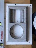
I have already built a base enclosure in my car that is the main constraint.
It's about a 250l enclosure for a custom sundown NSv3 18 that I measured with DATS:

1707475927797.png


Currently the enclosure has a 24cm (10") wide 100cm long round port in it with a 90° bend in it that takes up about 50l of the enclosure and tunes it to about 24-25Hz.
I am not currently able to measure the sub, but I have an old impedance measurement from when it was in an IB setup:
1707476094848.png

I think it looks exactly like the Zv3 18 impedance, just with an Fs of 20Hz instead of 30Hz, so I used the semi-inductance parameters from here:
https://data-bass.com/#/drivers/5bec9a847950b30004de5b9b?_k=goo6c4

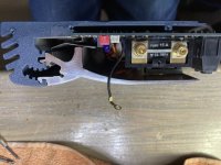
Here is a measurement of the current "trunk wall" enclosure that is sealed off from the trunk:
(This is with a DD715, but it gives an approximation of the cabin gain at the listening position, as there is no moving the enclosure.)
1707476288335.png


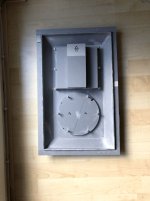
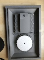
Now I realized I have the room to make a 100-120l front enclosure behind the rear seat:
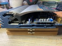
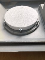
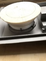
(This is a pic with the NSv3 18")
1707476520268.png

I can build all the way up to those round braces on the sides and then a little more.
The third of the rear seat in front of the port can be felled down separately and I plan on keeping it that way most of the time.


So I came upon the HROAR design, which I thought would be impossible to fit in this space with this massive 18", but I came up with this design:
1707476695283.png
'
This is a drawing of the enclosure with approximated sizes. One square is approx. 10/3cm and the whole enclosure is 40cm tall.
The front chamber has an average depth of 30cm.

Now I still haven't found out if I can model this in Hornresp, because it's not a 6th order, nor an 8th order, nor a tapped horn.
Because I modeled it from the beginning as a tapped horn, but realized the simulated output was at the horn end and not at the front chamber port:
1707477007468.png


But the output was amazing compared to the current design:
1707482446498.png


So what if I just added the front chamber in front of the existing enclosure:
1707477179686.png

It's a lot better, but not as good as the tapped horn...

And one problem with this is still, that at 8kW of power, the 10" port is compressing the output severely, at least based on the port velocity:
1707477303697.png


So I thought, what if I simplify the initial HROAR design and increase the rear chamber volume and shorten the port, somehow, does it just become a series tuned 6th order bandpass?
1707477443365.png

1707477531117.png

And now I have close to the same output as with the tapped horn/ HROAR.

But I'd still have to model it more intricately than what Hornresp is able to do.
I should be able to offset the rear chamber and the "port" between rear line and front chamber and I should be able to model it with an expanding line in the rear, because I can't fit the current rear port any nice way with a constant port area without going into the boot of the sub and without wasting space in the rear. And I wouldn't want to make that many 180° bends as in the initial drawing.

It would have to be a double bass reflex with an additional chamber in front, or an 8th order with the driver between the second and third chamber, not first and second.

Is there any way to come closer with Hornresp or do I have to learn Akabak?

Any help with this or some comments on my design would be appreciated.

LF rollof for bass amp?

Thinking about a bass guitar amp, in particular using a bass reflex cabinet. We all know that the driver becomes more and more unloaded the further you go below the box and port tuning frequency. Seeing the lowest intentional frequency of a bass guitar is 41.2Hz, would it make sense to tune the box at or maybe just a little above this frequency and have a fairly sharp filter to cut everything below this? I imagine the guitar strings being randomly struck while playing would produce subsonic signals that would possibly overload the amplifier and in particular push the speaker unnecessarily seeing it would be nearly unloaded at subsonic.

Would the high pass filter affect the sound much seeing it allows the lowest musical pitch through.
Are bass reflex cabinets considered a good idea for bass guitar or not?

Stereo Guitar Power Amp - Class D?

So I have a few rackmount stereo power amps, a tube guitar head, and a bass amp...

Reality is that for guitar, I'm moving more to modelers and the sort, so am thinking about a small stereo power amplifier than can do maybe like 40wpc at 8ohm, which would still be a lot.

Curious tho, I am always into the Class D chip,s, and have a few boards etc... and wondered... Is that gonna be my best bang for the buck in regards to getting clean watts cheap? I know there are more elaborate ways to go about it, and read that MOSFETs sound better than OpAmps when they overdrive, but believe any FET based amp will be much more expensive and complex, yes?

Any help is appreciated, as I've never given much thought to this before and searches aren't turning up a ton I can go off. Thanks in advance.

Scanspeak 22W/8851T00 bass drivers

Dear diyAudio readers,

I am selling a pair of Scan-speak Revelator 22W/8851T00 bass drivers. They have been used once and only for testing. Overall they are like brand new, minor scratches inside mounting holes because of the screws.

Price is 500eur/pair (retail is around 750eur/pair)

I can ship worldwide, however would prefer Europe.

Attachments

  • bass.jpg
    bass.jpg
    213.5 KB · Views: 116

Scanspeak D2908/714000 beryllium dome tweeter

Dear diyAudio readers,

I am selling a pair of Scan-speak Revelator D2908/714000 beryllium dome tweeters. They have been used once and only for testing. Overall they are like brand new, minor scratches inside mounting holes because of the screws.

Price is 800eur/pair (retail is around 1200eur/pair)

I can ship worldwide, however would prefer Europe.

Attachments

  • tweeters.jpg
    tweeters.jpg
    235.8 KB · Views: 141

2-way OB using BG Neo10 as mid/tweeter

Hi all,
I'm thinking of making a 2-way OB using parts from a very old buy order that never were used:
  • 2x Eminence Deltalite II 2515
  • 4x BG Neo10

The initial plan on the day was to make a 3-way using Raal as tweeter (maybe for sale soon), but my hearing today is almost non existent on >9khz, and that's why I'm thinking of using only the Neo's from around 200/500hz and up.

I would be going active with a MiniDSP, so maybe EQ the rising response is not a problem, but I've read about Neo10 beaming on 5-6Khz and up.

Not pretending the ultimate system, but yes something with very good bass and mids (I'm not a bass head and my music preference is mostly vocal).

Open to read opinions. Thanks!

Looking for the advice on which alps blue velvet potentiometer to replace a linear potentiometer "fader" on both channels of a pioneer Djm 450 mod.

Hello. Long time reader first time asking for help on a thread.. I have some experience. My father was a master electrician and had me practice soldering In my early teens.. I'm 46. I have previously modified a Xone 23C to rotary years ago but it was a kit so I am not sure which alps Potentiometer to choose for both main channels. I have spare PC boards to replace broken faders that just lock in to the main board so that I don't **** the mixer up. I will drill holes in the faceplate where the faders used to be until I can source a new one minus the fader slots.

Pink Triangle Anniversary battery PSU

I have operation problems with PSU battery of my PinkTriangle Anniversary.
In concrete terms, the turntable works regularly when powered by the mains, if the power supply is connected to the batteries the turntable does not work. The good condition of the batteries is obviously beyond question. Probably some passive control component on the battery circuit is malfunctioning, but which does not have the original circuit drawing. The English manufacturer does not have these drawings, and the designer (John Westlake) cannot be reached. I wonder if anyone can give me some useful suggestions.

Thanks
Massimo
Projects by fanatics, for fanatics
Get answers and advice for everyone wanting to learn the art of audio.
Join the Community
507,786
Members
7,888,453
Messages

Filter

Forum Statistics

Threads
406,240
Messages
7,888,453
Members
507,786
Latest member
alexhmao