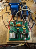
Building Elvee's Circlophone: Documentation, Parts, Accessories, & beginner friendly
Intro
Circlophone is a new topology (a more efficient Class A, dynamic class AA), with a live sound character and an easy build. These are fun!
♦
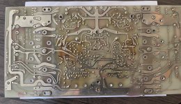
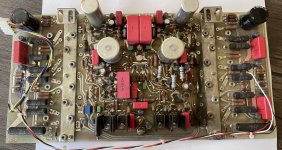
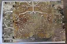
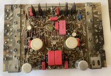
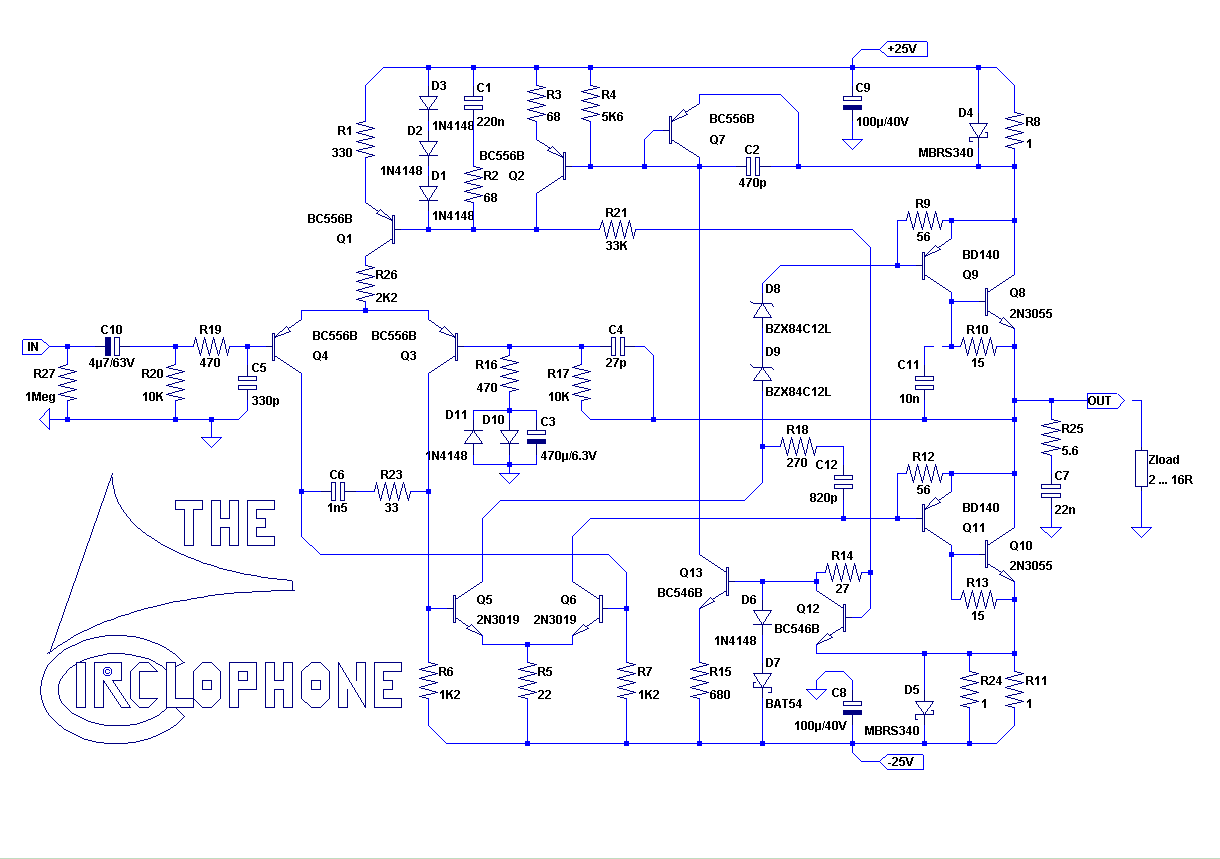
The Original, optimized Circlophone
♦
The Germanium Circlophone
♦
Inverted Jfet Circlophone
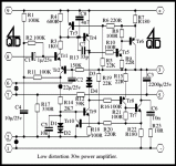
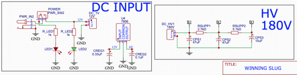
Sample schematic:
Parts options
♦ Q9, Q11 Driver: KSA1220, 2SA1930, 2SA1837, 2SA968, 2SB649, Philips/Harris BD140, and ST's BD140.
♦ Q5, Q6 VAS (cob 4pF~16pF): 2SC5171, 2N3019, 2SC3421, 2N1893,
MosFet; Or if < 5pf like 2SC2911, BF819, add
this cap.
♦ Q12, Q13 Sensor: BC546B on 25+25vdc rails,

With higher voltage use KSC1845, 2SC1845, 2SC2240, 2SC2705 or 2N5551.
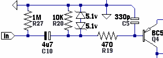
♦ Q4, Q3 Input: A Philips/NXP BC556B (post 7) is on the original, or nicely HFE matched BC556C or BC560C with a multimeter.
♦ Q8, Q10 Output: MJE3055, BD249C, MJ802,
MJL21194, MJW21196, MJ21194, MJ15022, MJ15024, MJ15003 or the
classics.
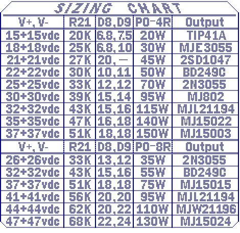
♦ D4, D5: Low voltage drop and high current handling is important, like 5a, 7a (MBR735), 10a (MBR1035) Shottky diodes.
♦ D8, D9:
see convenient sizing chart.
♦ D7: BAT type "Signal Schottky" like a BAT86, BAS86, BAT85 or BAT54, available at Mouser & RS. Or there is an
alternative.
♦ R21: "The value in KΩ ~ = 0.9 times the total AC supply" Or
review Elvee's selection guide. Or,
see convenient sizing chart.
Build specific:
♦ VAS on Piersma's Circlophone CFP build can be Sanyo 2SC2911 or 2SC3955, or similar specs.
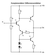
♦ Terrangima's Darlington & MOSFET Circlophone has its own devices listed on the schematic--See post#226.
Notes
♦ Discussion of topology and modifications:
Circlophone discussion thread
♦ Various brands of 2N5551, 2N5401:
Quality Control--check the HFE
♦ Various brands of 2SB649,
Quality Control: Click Here
♦ If using faster output devices,
click here and install C11.
♦ Other parts selection questions?
Here is a link to Elvee's build notes.
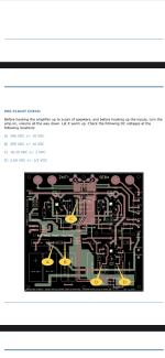
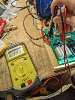
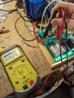
♦ Checking R21,
Elvee said: "Measure the voltage, divide by the resistor value, if it's 1.5mA +/-50%, it's OK"
♦ While you're measuring, it is also easy to check the
idle current.
♦ Elvee's LTSpice
Circlophone simulation file for the original Circophone.
♦ For an example parts list, aka
BOM (Bill of Materials):
Click here.
Accessories
♦ A Jfet buffer isn't mandatory but if you want one for constant input impedance,
click here.
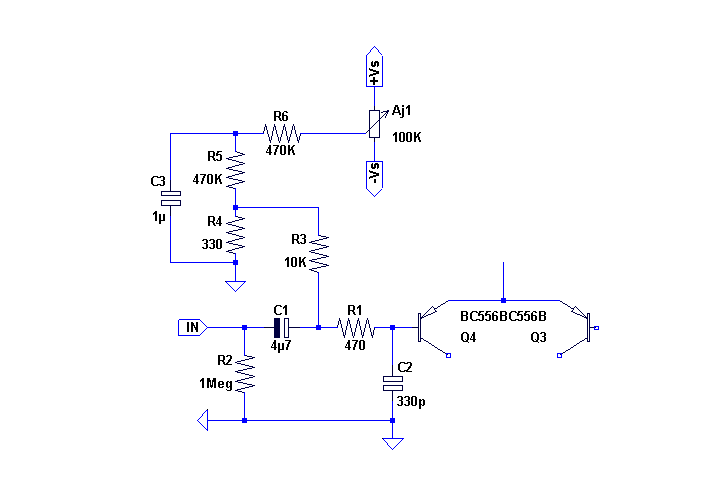
♦ To solve offset bounce versus power issues, Elvee has published an optional
offset trimmer circuit.
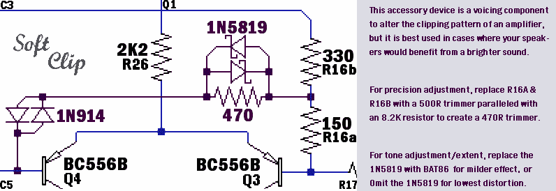
♦ Circlophone has Class A sound but if your sound is too mellow there's compensation in the
LTP soft clipper.
♦ If you have efficient speakers in combination with big gain for big dynamics, you might want
a limiter to stop x-max.
♦ Circlophone has very simple power supply requirements so regulated is unnecessary, but if you wanted regulated
click here.
♦ To block thumps from single rail sources (computer) power up, and block some RF too since it is slightly capacitive,
look at this.
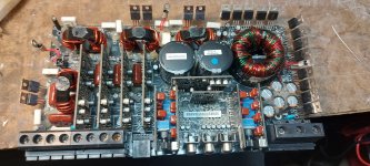
♦ Circlophones go in the house, at work
AND:
Boostor, a companion for a Circlophone on the move, rock the the car, RV and boat too!


![IMG_1759[1].JPG](/community/data/attachments/1215/1215591-5cadacd7f437b82099eca3f21b5845ae.jpg?hash=XK2s1_Q3uC)


