Small Sub Recommendation

I figured rather than driving myself crazy(er) that I would just ask on this one. I'm looking for a small subwoofer driver that I can use in a 3 way design. Would like to get a pair to run it in isobar. I would be matching them with a RAAL 70-20 and a purifi 6.5" driver (still haven't decided which). I'm already aware of a few that may fit the bill from dayton, kartesian, and misco, but I figure I would just ask around to see if there's anything I missed. Any help is appreciated 🙂

For Sale Rotel RKB-D850 8 Channel Amp (Hypex)

8 Hypex UCD modules (50 watts per channel). Rotel did a good job with this amp. The chassis is well ventilated, and there are 2 fans on the back in case it does get too hot. I've never heard them. The chassis is very robust.

Has optional digital inputs, and 12V triggers

$600 plus shipping from NV OBO

Attachments

  • 20240415_191340.jpg
    20240415_191340.jpg
    397.7 KB · Views: 87
  • 20240415_191203.jpg
    20240415_191203.jpg
    220.2 KB · Views: 96

simple software to create a 2 way bookshelf speaker?

Hi there.. any syggestions for box size of a 2 way bookshelf speaker .. I have allready the cross over.. its a kit.. but they dont suggest a "box size" - I have found software to calculate for a SUB that I also want, but I need to find out how big/small that box for the tweeter and midtone has to be... ( I am thinking about cutting from 80Hz and down and let the SUB handle the rest "bass") ....

Single ended output Open DRC-DA8 into balanced input ICE Power 1000ASP

I am assembling an ICE Power 1000ASP power amp (with a 1000A "hanger" board for a second channel) to drive a new pair of subwoofers. I just realized the amps only have balanced inputs, with +/-12.8 volts specified as the input voltage limits. My problem is that I want to drive this amp with my miniDSP Open DRC-DA8, which has only single-ended outputs with a 2 VRMS range. I'm assuming I'll sacrifice a lot of dynamic range, and risk high noise levels, unless I convert the DRC-DA8 to a balanced signal before sending it into the 1000ASP/A.
  1. Is my assumption correct?
  2. If correct, what are the options for making the conversion?
I've seen "active DI boxes" that seem designed for a similar purpose. If they are appropriate, are there characteristics to seek out or avoid? Or, would a pair of DRV134PA line driver chips inside the ICE Power 1000ASP enclosure be sufficient? The ICE power supply provides +/-12 VDC outputs to drive accessories, so the power is already there. I have no experience with those chips but implementation looks straightforward.

Thank you in advance.
Few

QUAD 99

Hi all, I'm after some help from the experts if i may. Ebay special, quad 99 power amp, the amp will not come out of standby. Im going to use as a stand alone amp so i have the selector on the "Input" but the red light stays a constant red.

I have attached some photos of the board, which it appears to me, has had a mod of some sorts. can anyone confirm what the mod is for? and by chance could this be to bypass the selector switch???

Any thoughts gratefully received. Thanks.!

PS thanks for the group!

current equipment: 2x 405's dada mods and re cap, 2 x 306 dada recap 1 x useless 99 😁

Attachments

  • top side board 1.jpg
    top side board 1.jpg
    897.5 KB · Views: 452
  • topside board 2.jpg
    topside board 2.jpg
    991.6 KB · Views: 453
  • underside mod close.jpg
    underside mod close.jpg
    821.6 KB · Views: 359
  • underside mod.jpg
    underside mod.jpg
    701.2 KB · Views: 362

It's remarkable how they can sell these speakers in the US for $299 the pair

JM Vera Fi Scout Revs 400ph.jpg


Here's a ported 2-way designed in the US and assembled in the US from mostly Chinese parts. Sold direct to consumer, the MSRP is $299 the pair. I'd say that they are cutting their profits pretty thin.

I have written a very "Long and Winding Road" review, because my readers like "Long-Form 'Think Pieces'."

At the end of the day, whether the compromises embodied in this speaker will work for you I think can only be resolved by an in-home trial. Fortunately, the maker offers an MBG.

But another way to look at it is, for $299 you get a nice-looking pair of cabinets, and you can either redesign or upgrade the crossover, or throw out all the innards (or sell them) and find nicer drivers to fit the cutouts!

https://trackingangle.com/equipment/vera-fi-audio-llc-vanguard-scout

amb,

john
  • Like
Reactions: Abhishmuk

For Sale Preamp

For sale a working preamp and it even works with universal remote control.With remote you can power on and of,choose input and of clurse volume up and down.But the remote is not included in this sell.I have using universal philips remote.This was a amp first,now the output amp modules are defective,I have take this out and made a nice sounding preamp out of this.The preamp section is the same like in Aaron no1. amplifier from Grrmany and have cost years back about 3500 eu.Look online.I have put some new caps on the modules and on the pcb some new nichicon psu caps and some new resistors.This preamp using one pair of single opamp per(channel) module.So you can try diferent opamps in this modules and tweek the sound colour.The pre will come with opa27 opamps!The preamp will be well packed and shipped.The price is 150 Eu including shipping inside EU!!! or best offer.I dont need this pre so if someone will play with this just make me some offer.The pre have 7 kg of weight.

Attachments

  • 20240603_170839.jpg
    20240603_170839.jpg
    729.4 KB · Views: 314
  • 20240603_170818.jpg
    20240603_170818.jpg
    767.6 KB · Views: 311
  • 20240603_170813.jpg
    20240603_170813.jpg
    565.9 KB · Views: 292
  • 20240603_170806.jpg
    20240603_170806.jpg
    673.8 KB · Views: 275
  • 20240603_170802.jpg
    20240603_170802.jpg
    730.8 KB · Views: 284
  • 20240603_170758.jpg
    20240603_170758.jpg
    812.9 KB · Views: 281

Greetings from Russia

Hello DIY Audio Community!
Mike, 52 y.o, live in Moscow.
I became interested in electronics and sound reproduction during my school years, I love when music plays loud and clear!
I have started with AM radios, then made some mods to cassette desks - the most interesting and successful was a dynamic bias like Dolby HX pro.
Despite the fact that I graduated from university with degree in electronics engineering for a living I work in the field of data networks, telecommunications and IT.
Throug the years I did repairs (amplifiers, SMPSs etc) but have no finished projects, what a shame)
Analog electronics remains my beloved hobby, as my kids have grown up now I have more time for my passion, even received a ham radio license!
For a long time was a quiet reader here, hope I can bring some value to the Comminity - there are many interesting topics.
Cheers!

RJ45 I2S. is there a way to measure if signal output works

Hello

I had to do a cable for I2S with RJ45 from my interface to my Aqua La Voce S3 dac
The signals from my interface are Data-BCK-WCK-MLCK. The Audio gd interface has a hDMI out so it is in balanced mode. I took the signal inside before the HDMI chip which takes unbalanced signal to HDMI balanced. There was 42 ohms in signal paths (Data-BCK-WCK-MLCK) that goes to HDMI chip. Il took them out to unload because I didn't want to feed HDMI chip. It was perhaps un necessary but... As it is, it doesn't work with the Dac.
Can I check with a scope if there is signal coming out of Data-BCK-WCK-MLCK ? MLCK is not used as I don't need it with R2R dac. The connections were checked many times and they are correct.
HL-MLCK- Dale are not used on RJ45.

Attachments

  • DI-20 RJ45 signal out.jpg
    DI-20 RJ45 signal out.jpg
    351.4 KB · Views: 82
  • LA Voce S3 Pinout.jpg
    LA Voce S3 Pinout.jpg
    54.5 KB · Views: 81

Help with class AB power amplifier design

I've been trying to design a Class-AB power amplifier using two Sziklai Pairs in the output stage, using BD140+TIP35 (the PNP pair) and BD139+TIP36 (the NPN pair).

The design is in the image I attached.

It has some a considerable amount of distortion in the whole spectrum, plus clipping when I try to amplify a larger bass signal, a reasonably treble and hard clipping much before the clipping should actually occur.

And the thing is that I think I don't know what I'm doing anymore. In the beginning, I tested the design in MultiSIM and apparently it worked, but in reality it had a ridiculously large RF instability that caused the current drawn by U2 (I used a multimeter in the same place of the one in the design) to increase by 10 fold (from 20 to 200 mA) when I simply connected two wires to the output, the wires being connected to nothing, just because of their capacitance. And when it did this there was a 100 R resistance limiting the total current in my source itself, could be much larger without it (I only removed it after making the circuit stable).

It took me long to figure out how to fix this, then I found this design that used a capacitor from the output to the stage before the output stage (C5).
Connecting a capacitor similarly (also C5 in mine), the instability went away, but I'm not sure if it makes sense in my configuration, even why here I had to keep its value small, otherwise there was much more distortion. With 100 uF there was distortion at low volumes even, with 1 uF it worked a lot better.

But still, no matter how finely I adjust the bias in the rubber diode, there's still noticeable harmonic and non-harmonic distortion, the worst being a hard clipping at larger volumes, in bass in particular.

But it's happening really before it should.

Q7 and Q8 transistors in my diagram should be limiters, activated only when the voltage drop on the 0.15 R resistances were around 1.4 V or so, so a current of 9A or more, which I doubt I'm hitting before this clipping I'm hearing.

Should I test removing them just for a test, or perhaps this is coming from another source?

Any way, I seem to never get a really good quality audio no matter how much I try adjusting the biasing rubber diode, the clipping isn't the only issue.

So I'm asking to check what flaws I have in my circuit that I should address.

Attachments

  • mycircuit.png
    mycircuit.png
    7.7 KB · Views: 315

Adding weight to a cabinet

Reading through some people's builds and recomendations I came across people adding a SIGNIFICANT amount of weight into their enclosures. On the order of 50-100 lbs.
I saw the saying "double the MMS" multiple times like its some sort of rule of thumb.
I have some plate steel sitting around doing nothing. I could add it to the bottom of the cabinet but does that actually make a difference?

Mofo+Hammond 193V+Nichicon ST

For sale a pair of completed Mofo boards plus a pair of Hammond 193V chokes for big mofo(24V supply and 2.5A bias) and Nichicon Super Through 15000uf 50V pair output caps.So all parts that you need by building a verry good mofo amp.All parts verry good condition,used but truly good condition,only the caps have some minor signs of use.Price for all together is 200 euro plus shipping inside EU.The shipping cost will not be low becouse the two chokes have over 10kg of weight.So plese ask first for shipping price.

Lightning damage

Not sure if it's the right forum. I've never dealt with lightning damage, but received a call from a buddy that there was a lightning hit near his house resulting in dead AC unit and some of his precious electronics. His expensive Mcintosh SACD and fairly recent tube amp appear to be dead. Mcintosh tube tuner connected to the same power strip survived , probably because it does not have a ground wire reference. According to him the stuff was turned off but I'm not sure it was turned off by the mains switch or simply on standby.
Maybe he should call his insurance agent first before we pop the hood off the gear? Not sure how those cases are handled.

Two part heat sinks - bad idea?

Typically for Class A amp builds DIYers are using aluminum extruded heat sinks for which the base and the fins are part of a single block of metal.

What if a heatsink is built up using a 6mm -8mm base plate with smaller heat sinks with fins bolted on? Would there be a lot of efficiency loss and concerns on thermal performance?

I have attached pics of a flat bar/ rectangular plate and smaller sized heat-sinks for reference. The heat sinks are 60 mm tall and 179 mm long - if we stack two and attach it to flat rectangular piece, then we can get a heat sink which 120 mm tall and 179 mm long. The pics are for reference purposes only. Ideally the heat-sinks can have a thinner base (4mm - 6mm)to keep cost (and weight) down.

Attachments

  • Aluminum flat bar 02.jpg
    Aluminum flat bar 02.jpg
    14.5 KB · Views: 139
  • Alu heatsink compact.jpg
    Alu heatsink compact.jpg
    76.4 KB · Views: 137

Lowther

I have just gone on the Lowther site:

https://www.lowtherloudspeakers.com/

which is interesting in a couple of ways. They have gone a bit upmarket. The factory made cabinets look much better made, with prices to match. £7000 - £18000 (+drivers!) that I looked at. The response curves look fairly realistic, (like the HF drop off at 9-10k) and confirm, that, without front horn loading, the PM6a 8ohm silver voice coil gives the flattest response.

However the most interesting thing I saw was that with the factory made speakers like the TP2 they recommend adding the “Lowther Super Tweerer”. A definite break with history.
  • Like
Reactions: GM

Amber Stereo 70

I've been away from this site for a while but in searching for Amber 70 threads I see there are a number of questions, however old.

I was a consulting design engineer hired by Keith Rosenfeld who owned the company. We were going to bring out a new line or products, including a super good preamp, along with an upgrade to the Amber 70 and a new product the Amber 200. Unfortunately, our venture group went bankrupt before we had the new product line out and that was the end of the company.

After the downfall, Keith shipped all the excess parts inventory to me, which I still have. If anyone needs schematics, notes, parts, drop me a line, I can send you a PDF at no charge. BTW, the LM391-90 chip is still available although the -100 is not. For the Amber 50 or 70, you can substitute it the -90 without a problem.

If you need something, drop me a private note. I don't repair Amber stuff anymore so if you need something, let me know, and I can ship it to you - along with any helpful hints and answer any questions you may have.

Janszen Electrostats Paired with Dayton RS225 - Crossover Assistance

Hello,
I recently purchased some rare DLK ULMs (electrostats made by Janszen). I believe these were the same units used on the Z-II CF which I owned and sounded wonderful. I contacted Janszen to see if they had any information on the unit and unfortunately, they did not. He did tell me they should play down to around 800hz and have a 2nd order (single L/C) filter ahead of the signal step-up transformer that rolls off below 800 Hz. The capacitor is a 4.7uf but I am unsure of the inductor value.

I have wanted to use the Dayton RS225s for a while. I'm tempted to build two enclosures with two RS225s in each and the electrostats sitting on top, I really believe that has the potential to sound amazing.

•Would the RS225 or RS225P be better?
•For load, would getting (2) 8 ohm and wiring in parallel, along with the Janszen in parallel be the way to go? Or, (2) 4 ohm in series with the Janszen in parallel?
•I do not have much experience designing crossovers. I would think a simple 1st or 2nd order would work. My concern is all the variables...load resistance, desired Q, flattening the x-over hump where the two drivers meet, etc, all come into play and I am unsure how to start.

PXL_20240412_193902341.jpg

For Sale Opera Consonance Calaf boards, tranny, hardware

Here are the guts of 2 stereo Calaf amplifiers.

All of them had exact same problem, bias board failure. Otherwise these are working boards.
You don't really need the over complex bias boards, instead you can place a normal adjustable bias circuit with a few components.

You get:
-3 complete boards, one gutted. 2 boards have also the copper heat spreaders in place.
-3 bias boards, which can be used for reverse engineering the circuit. Otherwise the schematics are available in the internet, except the bias board schematics.
-Power transformer for 2 channels
-1 power supply board for 2 channels
-pre cut insulator pads for 2 channels

Output boards have genuine Toshiba 2SC5200/2SA1943 matched pairs. All together 21 matched pairs. Also you will get 24 PC's 10000uF/80V Nover capacitors.

I'm asking 200€ for the whole pile or reasonable offer. Can be shipped almost anywhere.

Attachments

  • PXL_20240616_121720879.jpg
    PXL_20240616_121720879.jpg
    758.1 KB · Views: 83
  • PXL_20240616_121750808.MP.jpg
    PXL_20240616_121750808.MP.jpg
    575.4 KB · Views: 89
  • PXL_20240616_121954172.jpg
    PXL_20240616_121954172.jpg
    479.9 KB · Views: 85

Plans for the Invader Bins anyone?

Hey guys,

Is there anyone with some decent plans for the Invader-Bins?

I cant find any in the original Speakerplans-Thread from nineleaves (all deleted).

All I found was this plan on 'Plans Systemes'.

But I think its one of the older Plans from nineleaves and also is reworked from Plans Systems (which im not sure if they are correct).
When you read through the Speakerplans-Thread you can read of a lot of fixed and renewed plans from nineleaves that he postet there.

I would love to have the original 'final' plans from nineleaves. Or maby a modded plan from someone who build and succeded? Maby also the Cut-Sheets?

Original Thread : https://forum.speakerplans.com/my-18-horn-invader-bin_topic11659_page1.html
Plans Systemes : https://planssystemes.notion.site/Invader-Bin-9eb124e9ffce423ead38b62d557e2ca3

With all the best,
C.

Attachments

Power supply.

Hi.
I've already built a bench power supply. Built is a stretch. Cobbled.
It gives me 24V 3A with current limiting single rail power. I believe it uses a crowbar to limit current.
I built the Volt and Ammeter using the Intersil chips in Led format. (Also built them in LCD). It has a temp regulated fan on the heat sink.
I built it so long ago. I can post pics if people have the stomach for electric gore.No Printed PCBs here...just hackery !
I'm sure it meets no standards....at all....except electric isolation. I think...hasn't caught fire , even under alot of stress.

Now ,I'd like to build a dual rail power supply. Using the Intersil ICs (Something about building your own meters).

The killer is the transformer. Shipping is quite prohibitive for a decent toridal transformer that can deliver say 1000w at Max 48v.
Though I suspect I can use 2 switch mode supplies in series an use the bond as Common and I'll get my +Vc/0/-Vcc..correct?

But any noise from the switch mode would insert itself into my unit ..correct?

Any recommendations on tried schematics?..the working ones. 😊.

It's been on my list for a while and I'd like too build 3 units of my own. Not because its cheaper, it isnt , but because it's fun.
The 3rd unit ,I will play once again with an Arduino to control it. But bumping this unit up to +/- 60v 10A. .
A finger in the right direction ( the index preferably) would be much appreciated.

Hi from Hamburg, Germany

Hi, I admit - I came here by Google because a member is selling NOS transistors.
I am an electronics engineer from Hamburg and mainly work on industrial electronics and music studio gear.

So my relation to audio is actually not so diy, although I built amplifiers in the past for my own use. But this has become a victim of lack of spare time unfortunately.

I hope to find some interesting exchange on audio circuit related topics here and, yes, maybe NOS components that become harder to find every day - or offer them if I see someone needs what I have.

regards
Stefan

Full Range Triangle

I've asked the question on the multi-way forum, but will post here too. I would be keen to know what FR driver you would suggest for this smallish stand-mounted triangular prism speaker. As I burn in the Alpair 6.2s on my home streamer, I'm becoming increasingly a member of the FR fan club. Speaker dimensions and volume will follow the driver, but volume most likely in the 4-10 litre range. Keen to seek a similar sound to my B&W 607s3s with forward mids and sparkly highs while retaining good bass performance. Can be sealed, ported or even TL (if a TL in a triangle exists!).

Attachments

  • FR Triangle.jpg
    FR Triangle.jpg
    58.6 KB · Views: 107
  • Like
Reactions: NeonDriver

Transmission line speaker? (fullrange driver)

IMG-20230212-WA0013.jpg

IMG-20230212-WA0003.jpg


Hi everyone, I made a pair of this speakers a while ago. I always though that's a transmission line or a "quarterwave" design. But is it really ?
They are made around the Tang band W8-2145 driver, blanda bowl (the large one 28cm) and a PVC pipe (about 210cm long and 6.3cm diameter). All of this sealed in a concrete base which incorporates the connectors. Sorry, I don't have graphs and mesures, but they sound good-ish to my ears.
First I designed this speaker with the 1/4 wavelenght type of enclosure, but now I'm wondering if it is a transmission line or a very long ported design.
Thank you by advance for your reply and feedback.

Building/modifying SV-S1616D 300B amp

I want to start a thread about this kit build process because after some tinkering and adjusting this amplifier sounds much better than stock, in my opinion, and will be far more reliable. So first thing I want to say is that I built this kit exactly to the guide/schematic and then started to make changes. First thing I noticed was how hot the output tubes were running. The schematic suggests running a 300b with 482 volts at the plate with 73ma plate current. In my opinion this will fry any standard 300b pretty quickly. So the first mod I performed was to bring the plate voltage down to 400. Mine was actually running at 495 and 75ma. So to get the voltage down you will need to use the purple b+ tap, not the red, and use a 5u4gb rectifier tube. This will get you to 400v and 60ma which is a more typical operating point for 300b. This is just one of the mods I have done and there are several more to discuss but I’m interested to hear about others experience with this kit before I move on to the other changes. I have attached photos of what my build looks like at this point. So please chime in if you have this kit. Cheers Thomas
0EE9A096-9B69-4B2D-AB2D-F746E79A6A86.jpeg
05F1CDEE-2B36-4FD5-BA15-F5C7A88C2B6C.jpeg

  • Locked
For Sale 3e Audio Amp and Power Supply Stuff for sale TPA3255

Hi Guys - More 3e Audio stuff that I bought and have done nothing with. Just want to move it on to someone who will make the project and appreciate it.

This is my first time and I hope it is OK.
Starting with:

AMP Balanced/unbalanced AUD85.00
PSU AUD75.00

Plus postage to wherever you are.

PayPal (family and friends.

Thanks

Dan

Attachments

  • 3e-audio-amplifier-board-stereo-class-d-balanced-tpa3255-2x-225w-4-ohm.jpg
    3e-audio-amplifier-board-stereo-class-d-balanced-tpa3255-2x-225w-4-ohm.jpg
    106.7 KB · Views: 90

New NXL550 R1.0 500 Watt MOSFET Amplifier Module

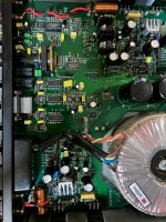
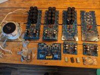
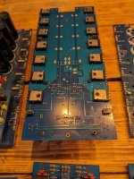
The NXL550 R1.0 amplifier module is a high performance, hi end amplifier module capable of over 500 watts into 4 Ohms and is 2 Ohm and 1 Ohm stable for short periods (60 sec).
Directly driven from an OPA462 High Voltage Op Amp.
It features the option of adding separate regulated input/driver stage supplies for even high performance.

The current power measurements were done on a +-70vdc linear power supply, higher power outputs can be achieved with voltage supplies as high as +-75 volts and with other versions that are capable of handling DC power supplies as high as +-90 volts DC.

The main PCB has an over temperature and over current LED status Flag which also serves as an output clipping indicator.

Specifications:

8 Ohms: 245W
per channel, powered from +-70vdc supply rails

4 Ohms: 425W per channel powered from +-70vdc supply rails

8 Ohms: 300W per channel, powered from +-80vdc supply rails

4 Ohms: 545W per channel powered from +-80vdc supply rails

Frequency Response: 20Hz-20Khz, -0.1db, 3Hz-210KHz, -3dB Input filter limited.

THD: 0.002%, 1khz, @200W into 8 ohms: 0.01% 10khz @200 Watts into 8 Ohms

IMD: 0.002%, @200W RMS into 8 ohms

SNR: -105dB, Unweighted, referenced to full output; -112.6dB A-Weighted

Damping Factor: 800 into 8 ohms, 100Hz

Gain: 22 (27dB) other gain options are available upon request?

Input Impedance: 22k Ohms Unbalanced:
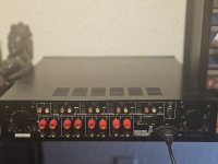
Inputs: RCA Phono

Recommended Linear Voltage Supply +-70 Volts DC
For higher power output +-75vdc can be used.
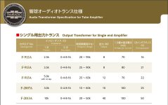
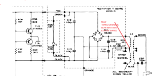
PSU Power Transformer secondary windings 50vac (800VA)
Printed Circuit Board Dimensions 105mm x 72mm
Small form factor PCB

NXL550 R1-1A.jpg


Captured Images Showing the following.

1Khz Sine Wave driving 8 Ohm load
1khz Square Wave response driving 8 Ohm load
10khz Clipping response driving 8 Ohm load
10khz Square Wave response driving 8 Ohm load

1khz SineWave NXL550 R1.0.png


1khz Squarewave NXL550 R1.0.png


10khz Clipping NXL550 R1.0.png


10khz SqrWave NXL550 R1.0.png

Question about Potentiometer / Volume control

Hi, I have a few questions on a simple matter . Most of the amps I've built never used pots for volume control, I used the signal source's volume control ( digital ) for that .
Now using the classic volume control with a pot like this :
Amp-Volume.gif
would this affect the quality of the signal ? or , change the input impedance based on the pot's location ?. Using a buffer before the pot would help ?.

What about this , would this be a better approach ? besides the output being inverted and not being able to have " zero volume ". would this affect the input impedance as well when pot is turned ?.
betterorno.PNG


What is the best approach for this ? Best way to use potentiometer for volume control ?. ( besides using digital volume control ic's )
- Bruno.

SME 3009 S2i phono DIN adapter

Hi-

Here is my SME 3009 s2i phono din socket adapter. It may work with others, but that is the only model I have. It is made to fit this connector https://zavfinousa.com/collections/hi-fi-connectors/products/rb-250-din-socket-replacement. As well as the shield from the RCA connector.

Attachments

  • 20240624_174321.jpg
    20240624_174321.jpg
    300.4 KB · Views: 52
  • 20240624_174335.jpg
    20240624_174335.jpg
    350.9 KB · Views: 58
  • 20240624_174341.jpg
    20240624_174341.jpg
    306.4 KB · Views: 57
  • 20240625_182929.jpg
    20240625_182929.jpg
    449.9 KB · Views: 54
  • 20240625_182938.jpg
    20240625_182938.jpg
    363.6 KB · Views: 57
  • 20240625_185404.jpg
    20240625_185404.jpg
    146.3 KB · Views: 53

Chinese Lab Gruppen clone

Hi All. Om working a Chinese lab clone Model Fp20k. 3 of the channels wont output more than approx half volume. The rail voltages on the output transistors dont cross +40 x -40 Volts dc. I have encountered this problem before but with a distorted sinewave. NEVER WITH A CLEAN SINEWAVE. IT JUST GOES TO APPROX HALF POWER AND STOPS at approx 65AC output. The problem is coming from the power amp board, Not the preamp.
Does anyone have any suggestions?
Thank you.

Analogue Audio Aria 2.0 Pre Phono

Hi my friends .. someone have a service manual or schematic diagram of Analogue Audio Aria 2.0 ??
https://www.tnt-audio.com/ampli/aria_e.html I have saw probably this manual in "hifi engine forum" but the registration is closed 🙁

I have one of this, power led go on and sometimes off to interval, but at the output no signal
Thanky you for your help


IMG_3290.jpg

Dali Opticon 2 MK2 crossover inductor upgrade

Hi everyone,

I have the good Dali Opticon 2 MK2 and would like to upgrade the crossover.
Dali is known for addressing the ferromagnetic hysteresis problem in its drivers through the use of the Soft Magnetic Compound (and Dynaudio and ATC also address the problem to be honest).
Now, in order to fully benefit from the driver hysteresis reduction, I would like to minimize this problem upstream as well.
At the amplifier level I use nCore, so I'm already quite calm because of the post LPF feedback.
In terms of crossover, however, I have some doubts.
Attached is an image of the Opticon 2 MK2 crossover. I don't know much about it, but the biggest inductor I think is related to the woofer, and I also think it's of the ironcore type (and given the price range I can understand).
The small inductor instead, presumably of the tweeter, seems to me to be air core.
Now I kindly ask someone if they can confirm this.
If confirmed, I'd like to know exactly what to measure of the ironcore inductor in order to identify an alternative air core, which keeps the characteristics of the crossover unchanged.
In this sense, with the same inductance, is it possible to find an air core with the same resistance?

Thanks in advance

Attachments

  • DALI-OPTICON-2-MK2-hangfal-keresztváltó_big.jpg
    DALI-OPTICON-2-MK2-hangfal-keresztváltó_big.jpg
    410.8 KB · Views: 681

GZ34 vs 5U4 vs Diodes

Hello! I'm powering a single ended stereo using one power supply. kt88 power tubes with two ecc83 driver tubes (one for each channel)

I currently have an old stock 5U4 rectifier installed and it seemingly runs great (decent plate voltage, bias is good, etc). Below is a screen shot of my current bias/tube dissipation.

Screen Shot 2024-06-23 at 6.06.55 PM.png


My problem, is when I use a modern GZ34 (i wanted a little more voltage out of it) it blows a fuse every time.

Am i exceeding the GZ34 specs? Would a diode set-up make more sense?

TBH I'm getting 330v on the plates, while the schematic is calling for 370v. Any opinions would be appreciated, thank you!

Linkwitz Transform before or after active XO?

I've got these custom made active XOs that are 2 way 24LR with an overall system HP at 15Hz LR4 to protect subsonics. They have 3 different XO points selectable by the dip switches. Currently I intend to try 100, 300 and 500. Or near enough as my resistances got me to. It is SE input, thru the LR24 filters and then buffered into the signal trafos that do SE> balanced. Quite nice things that I hope work well for me.
IMG20240530175704.jpg

I want to try adding a Linkwitz transform to the LF section...see if my amps and woofers can handle it!
I guess I need to put the LT after this LR24 but I wasnt sure about the balanced output of the trafos into an SE LT PCB. I'm sending the LF section of this XO into mono 3255s that accept a B input so would be a shame to lose that.
So can I do the LT on the 'entire' signal before the active XOs when I'm all still in SE? I didn't know about sending a boosted LF signal thru the trafos.
Thanks

System with both active and passive subwoofers

I have a set of MB Quart QM340CX which is separated 3-way speaker system comprising 1” tweeters, 5.25” midranges, 10” woofers, and 3-way passive crossover networks. I also have a pair of 8” KEF KAR 200B subwoofers. I plan to use them with a 5ch amplifier; Soundstream Reference 405. The 405 can be used in 3 channels mode, by bridging ch1 with ch2, and ch3 with ch4. Anyway, the midranges and tweeters will be installed at the front doors and the subwoofers are planned to be installed on the rear parcel. Because the MB Quart subs utilize PASSIVE crossovers while the KEF subs will receive filtered signal from the 405’s built-in ACTIVE crossovers, I wonder if installing those 8” KEF and 10” MB Quart on the same rear parcel, will the sound that is formed by different signal interfere with each other and causes bad sound?

The Denon DCM Series CD Player Repair Thread

Since so many of these inexpensive players seem to have a high rate of failure, I thought it would be a good idea to have a thread dedicated to their repair.

I'll start with the player I'm currently repairing 😉. I bought a DCM-370 from a seller who openly disclosed that the player needed repair. When it arrived, it would play bits and pieces of audio throughout a disc, with a lot of long-distance skipping. After attempting to clean the lens, lubricate the gears, etc., etc., the problem didn't improve. Actually, the more I used it, the less it played until it eventually couldn't even read the TOC.

Knowing that most instances of these problems were solved either by replacing the laser or the sled / spindle motors, I elected to purchase a whole new assembly (pickup, mechanism, everything). When I put it in the player and tried it out, it wouldn't spin the CD. I figured the spindle motor on the new assembly was dead. To confirm it, I took the new laser and put it on the old assembly. Still no spin. I thought this was odd, so I put the old laser on the new assembly, and lo and behold, the disc spun! However, it made the same clicking noises it had when it was on the old assembly and failed to read the TOC.

Any suggestions?

Transformer Leads Gauge Quick Question

Hello, I just received this PT, 225VA, 230V to replace the old 120V unit, maker is Amplimo Holland/UK, they made the old one so it should drop right in (famous last words). Only thing I noticed are the very thin primary leads, solid core and about 22awg, apparently they are the winding run outside about 20cm as flying leads. I've seen this before on tiny units in old radios never on a big transformer, off hand seems a little worrying connecting these to the 230V mains. Every other PT I've used of whatever sort had stranded leads spliced on and buried inside under the tape. From the PT to the switch will be right around 20cm, not very long, so I'm guessing the leads will be fine but thought I'd ask just in case.

My instinct is to splice on 20 or 18awg leads right at the exit of the wind, solder, shrink, fit a bit of vinyl tubing over it all for aesthetics, and off to the races. Thin solid core likes to break too unless handled carefully, not that I intended to handle it much. But, I've also learned to leave well enough alone, don't look for trouble, don't cut wires that don't to be cut, and assume the maker knows more than I do.

Curious what people think, is it 100% safe to connect to the switch and mains as is? Better to splice on thicker stranded wire?

Amplimo Primay Leads copy 2.jpg


Old 120V PT still in place:

2.jpg

Pipe Dreams … 50hz Helmholtz resonator out of PVC pipe. Bass trap or money trap?

Be gentle please
😉
looking for some advice on PVC pipe resonators 
Pipe dreams??????
Trying to get rid of this 50hz hang in the room. Got some PVC pipe and got them to resonate at the frequency I wanted. Three 10ft pipes basically cut in half and a neck added to lower frequency. Added some poly fill to see if it did anything. Do I do 3 more or am I just wasting my money?

https://vimeo.com/894328084/979b8b537f?share=copy

Before and After 80ms-160ms Decay.jpg

Class G type cascode buffer

I just read from the latest tubecad blog that Nelson had in the past a design where a cascode is used to create a very efficient Class A buffer amplifier. Principle is similar to Class G but the higher cascode Mosfets (used for high power) are slightly biased at all time to avoid switching in and out when higher power is needed. Seems like a very interesting concept but I do not notice any discussion on this concept in this forum so far. Is there any reason why this concept never becomes a working project? I am planning to test out this concept and build a 20-25W class A buffer.
https://www.tubecad.com/2024/06/blog0603.htm
  • Like
Reactions: wdecho

Hello from Brisbane Australia

I'm a hobbyist woodworker who enjoys good music Jazz Indie and more. All my woodworking projects so far (mostly furniture we use in our home) helped me learn a new skill. I would like to try my hand at building a really good looking and sounding set of speakers and I am sure this will test my skills and teach me a few new ones. I found some interesting discussions in this forum, so I decided to join in the fun.
  • Like
Reactions: Stanislav

Toroidal Transformer for QUAD 606

I have just bought a replacement Toroidal transformer asked for Secondaries: 2 x 0-80V.
What i actualy got was (80v 0v 80v) which is only one center tapped winding.
The quad power supply circuit shows two independant windings which is why i asked for 2 x 0-80v
windings.
I have attached a screen shot showing the quad power supply with a separate winding for each channel with a virtual earth.
My qustion is will the power supply circuit still work now the transformer windings are actually effectively
connected to give center tapped 80v 0v 80v. see attached screen shots.
Each rectifier will now be connected together at the center tap.

Attachments

  • QUAD 606 SEPARATE SECONDARY.png
    QUAD 606 SEPARATE SECONDARY.png
    68.7 KB · Views: 156
  • QUAD 606 CENTER TAPPED SECONDARY.png
    QUAD 606 CENTER TAPPED SECONDARY.png
    71.7 KB · Views: 180

Muffsy is distorted, Why?

With record on the platter, tube line stage and tube amps warmed up I set the needle down carefully on the record. No hum but rather distorted sounding. After trying different cartridges it was still distorted and my hopes were somewhat let down.

I pulled out a record I knew was in great shape because it had only been played one time in its life still no joy. I played with the gain switches still no help. I pulled out the input opamp a OPA2134 and replaced it with the only thing I had laying around which was a TL082 and fired it up again and it wasn't distorted but it sounded kind of lifeless. I surely shouldn't be overdriving it with a Pickering XV-15 D1200 cartridge which should output 5mv.

What could I have done wrong? Power supply measured correctly at +15.16 & -15.12 voltage on opamp pins 4 & 8 is correct

Any ideas?

Naim Nait 5 Service Manual wanted

Hello all fellow members and friends, I am looking for a service manual or schematics for Naim Nait 5 (not "i" model) amplifier. The problem of this unit is that the signal levels on both channels are not equal. Investigating the signal path, I assumed digital volume control is not working with same way for both channels OR signal level is not equal before this. Unfortunately, it is too difficult to decrypt circuit without schematics.
Thanks anyone who will reply.
Regards,
John

For Sale Amplifier Denon POA T10

p23q0y9i.png

Hello for everyone..
I am selling here my Denon POA amplifier in perfect working conditions and mint appear, selling here
because I do have more equipment of the same kind but can't stay with everything also for invest in
other stuff so looking for a new owner. payment by PP
Price is 440€
Regards

Attachments

  • tyiougua.png
    tyiougua.png
    272.8 KB · Views: 123
  • w0ukcn3k.png
    w0ukcn3k.png
    275.3 KB · Views: 135
  • 7pb8ydd5.png
    7pb8ydd5.png
    304.4 KB · Views: 139
  • vgogmb3u.png
    vgogmb3u.png
    271.9 KB · Views: 149

Vituixcad - getting started, apply baffle step simulation?

I am just learning Vituixcad. I have managed to model my crossover for a relatively simple 2.5 way tower speaker using the Satori 6.5 papyrus midbass and the TW29 silk dome tweeter.

I am using the ideal /infinite baffle traces for now, as I am still building my enclosures.

I see that I can use the Diffraction tool to model the baffle step that my front baffle would cause.

However, I am unclear how to apply / overlay this baffle step back to my response graphs? Is this possible?

60 degree quite compact 3 way Synergy horn

Curiosity and wanting to make something got me into looking at the feasibility of a 60 degree Synergy horn.

This would be purely for Hifi volume listening / Home Theatre use.

Using 2 x 8" LF drivers - Faital 8PR200s (as the SM60F) or Eminence Beta 8As (I know I like the Eminence Kappa 12A sound, but don't know if that counts for anything, but they are cheaper).. or plenty of other 8" drivers.

For MF and HF - instead of going coaxial, how about a 2.5" or 3" (if it would squeeze on), sealed back paper cone driver pair, or even 4 of?

There are plenty of 100Hz to too more than plenty high small drivers.
Peerless do a closed back one that's looks good.
Dayton and others do too.

Then on HF my trusty Vitavox S2 compression drivers.

I know I like the S2 sound - already used them on Tractrix and Le Cléac'h horns and have them currently on the SH50-alikes I made, after trying and not finding the BMS4550s to my taste.

I've been measuring up and jiggling a to scale'ish plan drawing.

Could be done with similar compact 530mm square flare as the SM60F.

I've not finalised the tap and port placings yet, but something like this.

Simple drawing for websites.PNG


What do the Synergy builders reckon?
Method or madness?

What is this called???

I have seen in a YouTube video a few months ago how they reduce the center to center spacing of a subwoofer array by covering each driver with a plate with two oval holes.

This is supposed to turn one driver into two separate point sources.

Is there a technical term for this? I scoured the net for an hour without any result.

I am trying to find out if;

....it really works
.....can it be done to midrange array
drivers too?

I have a pile of wonderful 12cm full range drivers that I want to cross over quite high ( around 6Khz) to a tweeter array.
Projects by fanatics, for fanatics
Get answers and advice for everyone wanting to learn the art of audio.
Join the Community
507,755
Members
7,886,793
Messages

Filter

Forum Statistics

Threads
406,160
Messages
7,886,793
Members
507,755
Latest member
busgroove82