I've been away from this site for a while but in searching for Amber 70 threads I see there are a number of questions, however old.
I was a consulting design engineer hired by Keith Rosenfeld who owned the company. We were going to bring out a new line or products, including a super good preamp, along with an upgrade to the Amber 70 and a new product the Amber 200. Unfortunately, our venture group went bankrupt before we had the new product line out and that was the end of the company.
After the downfall, Keith shipped all the excess parts inventory to me, which I still have. If anyone needs schematics, notes, parts, drop me a line, I can send you a PDF at no charge. BTW, the LM391-90 chip is still available although the -100 is not. For the Amber 50 or 70, you can substitute it the -90 without a problem.
If you need something, drop me a private note. I don't repair Amber stuff anymore so if you need something, let me know, and I can ship it to you - along with any helpful hints and answer any questions you may have.

I happened to own one Stereo 70 with blown outputs and defective lm391n-100. had order ed 391n-100 on online store as well as the 2n5886 and 5884. I want to upgrade it since these one still don't have the zener reg for the chip. it was directly fed from the rails. Do you have the latest version of the schematics?
I do have the schematics and fortunately Amber never changed the reference designators on their circuit boards; as they had several iterations. Consequently, they never had to change their schematics much. Drop me a private note and I will send them to you along with a bias procedure. BTW, a lot of amps went out with 150 mA bias, as they were trying to run Class A over most of the output but it turned out the emitter resistors are a bit too small for that level of current. It is best to keep the bias current around 40 to 50 mA.
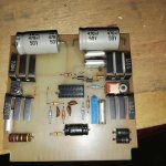
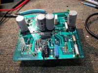
Yes, that is one of the intermediate boards - not the earliest and not the latest. The circuit however did not change. The changes were for manufacturing issues rather than sound quality. The four small silver capacitors should be replaced with newer polypropylene devices of the same value and the same or higher voltage. That black, 47 uFd non polar capacitor should be bypassed with a 5 uFd polypropylene device. All of the semiconductors should be replaced, including the output devices, and adjust the bias for 50 mA. This amplifier should operate again while sounding better than the original.
Yes, that is one of the intermediate boards - not the earliest and not the latest. The circuit however did not change. The changes were for manufacturing issues rather than sound quality. The four small silver capacitors should be replaced with newer polypropylene devices of the same value and the same or higher voltage. That black, 47 uFd non polar capacitor should be bypassed with a 5 uFd polypropylene device. All of the semiconductors should be replaced, including the output devices, and adjust the bias for 50 mA. This amplifier should operate again while sounding better than the original.
Yes I will try replace those caps even the electrolytics. The output transistor will still be the same but i have old MJ802/Mj4502 or 2N3773/2N6609 pairs to try.
Like the attached pic from net is what I have but different color. Grayish.
Attachments
You won't need to replace the electrolytics, unless they are bad. The bipolar one could be replaced with a plastic one but the physical size makes this very impractical. Be very careful when swapping out driver transistors or output devices with other part numbers. It is easy to compromise the stability of the amplifier and there is no point in burning something up while trying to save a couple of dollars.
I had secured the original output trannies but the drivers I can't find here. I may try TIP41/42 instead or any TO-220 pair with close specs with the original.
By The way main issue was the supply rail. Our mains is at 220v or less. Since the trafo is designed for 240v primary so the secondary drops at almost 29vac and get raw dc at 38v far from 43V. So the zener for the chip supply is 39v, it will not work so i might lower it down to 34v instead. This might cause in decrease in power output.
Another option is, I will provide another small trafo just for the chip supply or make a doubler on the existing supply then regulate it (But it's too high). Anyway there is still enough space on the chassis.
I have a series 70 in very good state but am considering changing the ps caps for 2 reasons . Age , normal maintenance and am considering going with double 22k uf per side. This would be an experiment in sound. I like the sound very much but the bass doesn't go as low as i would like . The bass is quite full but not as low as my other amps . Other than that the sound is very nicely balanced.
My Amber 70 was purchased new in Summit NJ in 1980/1 when I was at Bell Labs. It's been a champ, but now the right channel fuse is blowing. I can start replacing suspect parts (LM319 is a good candidate?), but further advice would sure help. I don't seem to have the level of privilege needed to privately message @SpatialKing - how to get in touch? I'm scnorth on gmail.
Hi last time i had conversation with him was thru email (March 2021). PM me i can give you his used last email address. he might help you.My Amber 70 was purchased new in Summit NJ in 1980/1 when I was at Bell Labs. It's been a champ, but now the right channel fuse is blowing. I can start replacing suspect parts (LM319 is a good candidate?), but further advice would sure help. I don't seem to have the level of privilege needed to privately message @SpatialKing - how to get in touch? I'm scnorth on gmail.
Now im in the process of rebuilding my AMBER series 70 with some mod by him. hopefully i can finished it this month. Busted output and missing Chip. Puchased chips and replaced . initial test was dc offset and it was very low. next is putting the output trannies and see if it will work.
This is not proper repair procedure. Replacing parts without evidence just injects more possible bad solder joints.. It's been a champ, but now the right channel fuse is blowing. I can start replacing suspect parts (LM319 is a good candidate?), but further advice would sure help.
First one puts a 60 W incandescent light bulb series the AC input to the amp. Mine is in a grounded steel housing with power cord, NEMA 20a socket, input circuit breaker(mine is 5A), holes to see the bulb light up. Enclosure keeps you or worktable from being burned by flying mains wires. Lamp sockets are for solid 14 or 12 ga wire, and instrument wiring is stranded.
Then replace the fuse, Power up. If lamp stays on, fault is cause . Then you can take voltages to point out where the problem is. Connect the DVM meter black probe to the black speaker return socket on the bad channel with alligator clip lead. Do not use two hands to take voltage measurements, >24 volts from one hand to the other can stop the heart. Wear no jewelry on hands wrists or neck, 1 v at high amps through a ring can burn flesh to charcoal. Wear safety glasses or reading glasses, parts can explode and solder splashes.
On bad channel I'd start by looking at Emitter to .22 ohm resistor on drivers Q1 Q2, versus center (speaker ground) voltage. Taking base voltages too, you can subtract B & E voltages to make sure they are 0.6 and -0.6 .
I disrespect previous advice to leave electrolytic caps alone, and replace the transistors without testing. I find 50 year old transistors to be pretty reliable unless overheated by dirty heat sink or abuse or speaker wire has been shorted. I find rubber sealed electrolytic caps at 50 years to be mostly trash. WIth only 4 or 10 e-caps it is not worth investing in a $120 ESR meter to test them. Besides ESR test is at 6 v and caps can leak a lot worse at 30 or 50 volts than they do at 6 volts.
I disrespect previous poster who replaced MJ240/250 with TIP41c/42c. MJ240/250 are (probably) 30-40 mhz FT parts. I replaced 50 mhz FT 2n5020/22 with TIP41c/42c and sound was dull and lifeless. Bad highs. If one can't find mj240/250 and they are defective, use MJE340/350.
Last edited:
Thank you for the very specific and helpful advice.
I don't have much experience or skills in this area, but I'm very willing to try new things.
Does the 60w bulb protect the amplifier while this work is being done?
The LM391s are socketed, but I agree that randomly changing components is not a good practice and can even create new problems.
I don't see anything leaking or other signs of damage anywhere in the amplifier.
It seems straightforward to replace most of the electrolytic capacitors. Except, I notice a lot of .1mfd "ITWT" (ITW?) capacitors, in rectangular packages with surface-mount leads on the side. I don't see identical replacements on the interweb. Maybe any .1 mfd film capacitor with the same specs would be ok.
After years of technical and scientific writing, including writing hundreds of reviews, it seems more productive to refer to submissions (or postings, or other contributions) and not to authors, except when intentionally dropping the boom. For example, "I strongly disagree with the idea of replacing..." or "It would not be a good idea" or "The performance of the amplifier will significantly deteriorate if..." and stay away from criticizing authors directly, even if it is implicit. This sometimes encourages a response that is also more factual and objective.
0.1 uf capacitor will probably be film. If no plus on one end, surely. Film capacitors last forever unless run hot for thousands of hours. I would take voltages before changing any part, to see where the fault lies. You can get the dim bulb device parts at the hardware store, no $10 freight required. Except the case, that has to be an old appliance or tool box or cash box from garbage or a flea market. If no holes for viewing lamp, drill a couple. If taking measurements you may also take B E C readings on the exterior transistors, the output transistors. Then mark on the schematic and post if you have .jpg editing software. Your rail voltages may be bad due to leaky rail cap. Both rails will be low & symmetrical with the light bulb lit if the fault is elsewhere. Nothing further should be damaged if powered up through 60 w lamp, but wear safety glasses anyway.
When changing e-caps mark plus on board before removal. If you put them in backwards, they vent the water out. New ones have a minus in balls pointed at the other end. I buy >3000 hour service life caps now from newark or digikey, so I don't have to do this again in my lifetime. I had to replace store shelf e-caps in my ST70 four times for cause. You won't be able to buy long life axial lead caps, just buy radial lead ones and bend the leads to fit, or splice on more wire if necessary. If wire is spliced, glue cap down with rubber cement or silicon caulk.
I believe previous posts or other threads indicate LM391 is no longer available, or has a different pinout. If find IC1 output hard stuck to one rail, will discuss modification later.


- Home
- Amplifiers
- Solid State
- Amber Stereo 70