Help ID Wu Gang Preamp please!

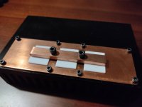
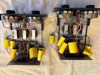
An old audiophile friend of mine, who is somewhat extreme in audio occultism lol loves to pot everything. Anyway let's not get into that(!).

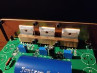
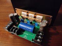
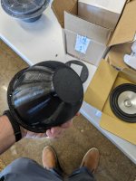
I'm in the process of soaking this preamp he gave me in a chemical bath for a week or so. Just because I wanted it clean and ready for future projects.

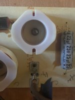
The only way of reversing this potting solution mess is chemical baths followed by tiny holes drilled into the potted layer then a final soak in super glue remover for 78 hours.
Sadly some damage is inevitable, the odd snapped resistor or diode here and there.


20240701_225359.jpg


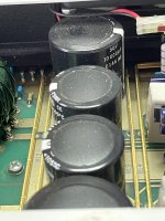
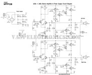
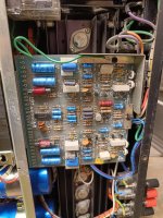
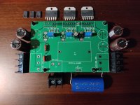
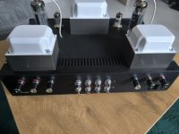
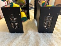
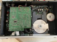
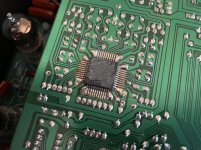
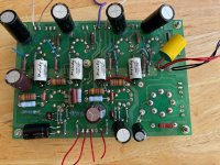
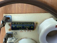
My question is does anyone recognise this board? It has a Chinese phone number and "designed by Wu Gang" on the board. I want to find photos of the original board online so I can get a better idea of the component list (board scratches sigh...).

20240701_225408.jpg


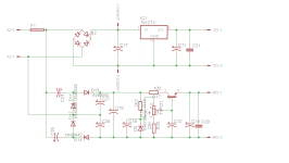
A schematic would be amazing however just some products photos would suffice.

20240701_225421.jpg


I know this one is a real longshot but I would be extremely grateful for any help with this preamp.

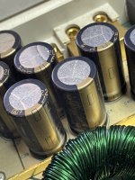
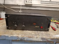
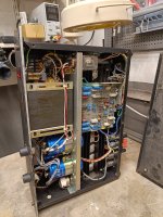
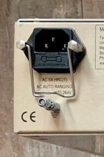
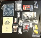
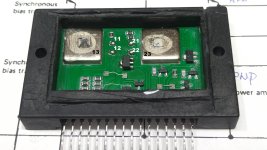
There's some Muse caps here, it came pre-built from eBay (eBay I think), and with a blue potted/cased tranny on a small power supply board with single fuse holder.

20240701_225445.jpg

Designing a solid state tube?

Schitt Audio has a preamp that is intriguing the FREYA+. It uses 4 6SN7 tubes. But here's the kicker... you can optionally purchase 4 "solid state" tubes. What are these? Well I assume they would have to be solid state circuits, in a bottle, with an octal base, that simulates the transfer function, curves, mu, rp, etc of a 6SN7 tube? So the circuit still thinks a tube is in the socket. Is this cool or what? Has anyone seen this concept used before with anything other than the old silicon rectifier substitute's?

Does anyone have a schematic of what solid state circuit might be fitted into an octal bottle to precisely impersonate a 6SN7? I'd really be interested in such a circuit that can be a plug in replacement of a tube, for study and interest.

https://www.schiit.com/products/freya-n
  • Like
Reactions: gerrittube

WTB RCA MI-9449 Cones & Original Binding Posts for RCA Driver circa aprox. 1940~1950

Hey there everybody,

Curious who ended up with the stock of RCA MI-9449 cones that auctioned a few years back? They were selling in lots of 60 cones at 4.5k, I'm not that loaded so I just watched 'um sell... I need a pair - but if I can afford it would like to buy 4 or 5 pair and have a lifetime-ish supply. Idk what's a good offer, you tell me:

1000004613.jpg


I'd also like to find a pair of this style of binding post, for restoring an RCA woofer which is missing them:

1000004297.jpg

1000004299.jpg

1000004300.jpg


I would also like to identify any other manufacturers that used this piece of hardware, so if you recognize them & their cleanly-machined square slots, and would like to share the knowledge of the other possible sources (I.E. I'd like to part them out of a cheaper driver), I'd greatly appreciate that information... I could try to info-trade, I sourced a replacement basket from a cheaper driver as the donor...

Please excuse the cat hair visible in all three photos. The culprit:

1000000924.jpg


Cat hair yes, but mouse poo, no. Everything in life is a balance of positives and negatives...
  • Like
Reactions: OtisCampbell

DC 12V and 48V from a single 12V AC transformer winding

I am trying to make a power supply for a microphone preamp.
I have a transformer with a 12V AC winding and I would like to obtain 48V for phantom power and something around 12V to power relays, LEDs and a vu meter buffer.

The first approach I tried uses a voltage multiplier which produces effectively the desired 48V, and a bog standard 7812 section for the other rail.
The two circuits work well independently, but not if they are connected together to the same transformer winding.
It looks like the diodes in the multiplier and the ones in the bridge rectifier are interacting between each other creating some undesired current paths.

I have tried another circuit borrowed from a JLM power supply and in this case the two sections work well together (I guess it's because C1 and C2 provide isolation between the two rectifier sections) however despite the schematic claiming you can get 48V from a 15V AC transformer winding, my transformer which in fact outputs 14.5V AC (it's rated at 1A so the voltage is increased with no load) can only produce max 36V DC on the output.

I am looking for any suggestions on how to modify any of these two versions to meet my requirements, or by all means if you have an alternative circuit to suggest for this application.

Attachments

Comparing P3A Schematics

So after my TDA7294 amp finally getting done with all the mods and options. I am now moving onto my P3A design. Full credit to Rod for his contribution to the DIY community.
So I purchased a few PCBs that are available to me in my country. Some are better than others. But all work.

My problem now is do I follow the values provided with these PCBs. Or do I follow the original design.
So far I have listed out the key areas of difference. I have then started to try each change one by one and see what sounds better and measures better.
But this is taking way too much time. Ideally I would like to just create a Simulation model. And keep changing values and seeing the results. Being new to Spice I can create the modell. But where I get lost is what parameters or commands would I need to monitor in the simulator.
If a spice expert could give me a starting point or list off commands to give spice.

I am attaching both schematics. The OG Rod vs the one I got with my local PCB.
In particular I'm curious about the value difference.
(When I first built this I kept blowing transistors. Then I had a lot of distortion).
All these problems were caused by fake components. The BD139 BD140 and main drivers were fake. One batch just failed. The other had a lot of distortion. No matter how bad the PCB is with the right components. This design just works.
The key areas where there is a huge difference in recommended values.
1. R3 / R39 = 470 ohms on Rods R6/R7=560 Ohms (I used 505.12 Ohms).
2. C2/C4 220uf/47uf on Rods C3/C5 100uf/100uf
3. R11/R12 = 220ohms on Rods R11/R12 100 ohms.
4. BC547 vs BC546 the implications. And I landed up using 2n2222 why because it sounded the best of all the ones I had on hand. Maybe psychological. lol.

There are a few other differences between the two schematics But I want to get to grips and understanding these 3 to start with.
If nobody responds. My backup plan is to just try both options measure noise and power output and just pick the one that sounds better to me. Im just curious were these values changed because they proved to work better or for some other reason.

Attachments

  • p3a-f1.gif
    p3a-f1.gif
    9.6 KB · Views: 771
  • 100 + 100w Amplifier Circuit Diagram-1.jpg
    100 + 100w Amplifier Circuit Diagram-1.jpg
    87.8 KB · Views: 1,884

HH MOSFET M900 DC offset 267mV when pot twisted to max?

i have set the bias on both Channels to 600mv
and set dc offset on Channel 1 to 0 mv

problem when offset stays at 267 mv when the trim pot is turned to maximum on Channel 2 ?

Attachments

  • IMG20240330165956.jpg
    IMG20240330165956.jpg
    561.7 KB · Views: 207
  • IMG20240330165821.jpg
    IMG20240330165821.jpg
    530 KB · Views: 191
  • IMG20240330170002.jpg
    IMG20240330170002.jpg
    637.8 KB · Views: 206
  • hh-electronic_m900.pdf
    hh-electronic_m900.pdf
    900.3 KB · Views: 194

Totally agreed with Mr Ohashi

Mr Ohashi's Blog July 1, 2024​

Translated by Google translator...

Silent Majority​

July 1, 2024
It has long been said that a ramen shop that 5 out of 10 people think is delicious is a very successful shop. In other words, it is impossible for 10 out of 10 people to think that the ramen is delicious.

I happened to be talking to a colleague today, and he told me that he was very depressed after seeing some nasty comments online. In this day and age, it's said that everyone is a critic, and if you do an ego search on social media, you'll find a lot of nasty, negative comments, but personally, while I accept those opinions, I don't pay much attention to them.

The reason we have been able to continue this work for 26 years is because of the presence of the silent majority (the majority of people who do not like to speak up) who support us, and because of the trust and gratitude we have from our users.

For example, there may be some customers who say "I don't like the taste of this restaurant" at the register before leaving. However, worrying about that and losing your individuality is a bigger loss. You can just look forward, knowing that your restaurant can continue today because there are customers who come to your restaurant without you having to say anything because they "like the taste of this restaurant."

Just as other people's faces are different, the taste of ramen and the sound of audio equipment are also infinitely different. Since they are made by different people, there is no way that the taste (sound) will be the same. Moreover, with audio, multiple devices interact in complex ways to create the final sound, so even if the device you happened to choose doesn't produce the sound you like, we should understand that there are various factors and backgrounds behind this.

For example, a customer came to listen to the headphones today. He brought his beloved Marantz 7 original and McIntosh MC240 in the rain. Both are in very good condition and in perfect condition.
Silent Majority_b0350085_00084542.jpg
Using the 4344 listening room, the demo units SV-310 and SV-8800SE were used for comparison, and by changing the order and combination,
a total of four different sounds were enjoyed.
Silent Majority_b0350085_00084597.jpg
Even with the same combination of vacuum tube preamplifier + multi-electrode tube preamplifier, the sound output is completely different. With the

Marantz + MC240, the mid-bass region is emphasized, giving the sound a full-range sound with a large grain. With classical Tutti, the sound is a little rough, but it is very attractive in terms of density. With the Marantz + SV-8800SE, the high-frequency overtones are added, giving the sound a sense of spaciousness and fine grain, but depending on how you listen, you could even say that the Marantz feel has been diluted. The frequency response of the power amplifier is more than three times different, so the balance of the sound's dominance has changed significantly.

Next, with the SV-310 + MC240, the elasticity and bounciness of the low frequencies add to the dynamism of the music. If you don't mind a somewhat monochrome, sour sound, this may be the best combination for old jazz.

The last combination we listened to was the SV-310 + SV-8800SE, which many people actually use, and the customer said, "This is the best match." To put it in a positive way, you could say that the richness of the SV-310's sound and the flexibility of the SV-8800SE are well blended, but some people may find it too straightforward and uninteresting (sound source).

...As with anything, there are two sides to the same coin. Where there is light, there is always shadow, so it is only natural that evaluations will be completely opposite depending on where you focus and how you feel. Chefs and audio retailers like us do not follow recipes written in a recipe book, but rather believe in our own sensibilities and techniques, so I told them that there is no need to be overly confused by the rare loud minority (a minority that wants to loudly express negative opinions).

It's okay if there are people you don't like... but rather, please take care of the fans of your amplifiers, I felt like I was telling myself that today. We just have to quietly believe in the majority of people (=Silent Majority) who don't like to speak out and continue to make things honestly today... that's all we can do in the end.

For Sale Rare Toshiba JFETs available on eBay. 2SK389V , 2SJ109V , 2SJ109GR, 2SK170BL

I hope im not breaking any rules posting this here. But i wanted to let people know. I know fakes on Ebay are common but my seller feedback will confirm that i have genuine Toshiba parts.


https://www.ebay.com/sch/i.html?item=126478127702&rt=nc&_trksid=p4429486.m145687.l2562&_ssn=jsaarl

Edit: i made a mistake in the post title. 2389V should be 2sk389V. I also have some 2sk146V for sale

Hello from Milwaukee

I used to be an EE, then became a dentist, and as of last year, I'm retired. I used be do a lot of DIY and looking to get back into it.
Current system is older stuff- a TEAC VRDS-20 CD player, Squeezebox Touch, Krell KAV300i amp, SVS 3000 Micro sub, and Kanton Ergo 22 DC speakers.

I recently recapped the Canton speakers, and I'm 95% done with a recap of the Krell amp.

Blog page on the Kantons here: https://drmrehorst.blogspot.com/2024/06/another-recapping-project-canton-ergo.html

There will soon be a blog page on the Krell recap - waiting for a few more parts to come in.

SWTPC Stereo Tiger Repairs

I've been out of pocket for health reasons for a while but all good now. I finally got around to swapping out the resistors that were overheating in my stereo version and swapped out the PS caps with new mallorys.
The amp performs like a champ except for one thing that was also an issue with my universal tiger mono versions back in 1975, a faint 60 cycle buzz that can be heard in between tunes if preamp volume is at a relatively loud volume. Is there any grounding changes that could/should be made to the amp that might help in this respect? It's still got the original no-ground non-polarized cord cap but I'm assuming with the inputs and outputs being grounded to chassis that going to a earth grounded cord to chassis may not be advised?

Interlude Audio: New HiFi Brand doing both commercial and diy type products

Hi, I'm Ron, from Interlude Audio. We've recently launched an analog HAT for raspberry pi and we're about to launch our digital HAT. We plan on making more mainstream commercial products as well, like DACs and smart amplifiers. We like the diy space and are wanting to create for the diy audiophiles out there too.

Let me know if you're interested in our brand. I'll be posting info about our two HATs in the Vendor Bazaar.

For Sale PA150 LM3886 based on jeff rowland, now with all parts..

1703355911891.jpg

PA150 LM3886 pcb with all components to complete now with Jantzen input capacitor for sale:87€
IC's are new and are not applied on the pcb,like main capacitors,power connectors and SMD output resistors
the other components are already assembled, with genuine components,like on the second picture.
Machined Heatsink with the machined copper hardware and ceramic pads can be supplied the cost is 68€,
It is available for purchase in another listing.
DRV134 and gold plated pcb can be supplied if requested cost is 16€
I have also power supply pcb's for who want one model the power supply can be used for powers up to 400watt
and the other for powers up to 800watt, power supply partial assembled as example.
More than one set available
Tracked shipment to European union
Skematics sended together with articles.
If you are interested in this kind of stuff check here:
https://www.ebay.de/usr/dialedinmusic?_trksid=p4429486.m3561.l2559

Attachments

  • 1703355034348.jpg
    1703355034348.jpg
    413 KB · Views: 250
  • 1703354878707.jpg
    1703354878707.jpg
    332.8 KB · Views: 235
  • 1703355118475.jpg
    1703355118475.jpg
    297.1 KB · Views: 216
  • 1703356014818.jpg
    1703356014818.jpg
    312.1 KB · Views: 208
  • 1703356201263.jpg
    1703356201263.jpg
    374.9 KB · Views: 202
  • 1680812128247.jpg
    1680812128247.jpg
    242.5 KB · Views: 200

For Sale Thank you diyAudio! I'm out of DIY … Parts inventory

Hi everyone,

Over the past 10 years I have learned much from DIYAUDIO.com and it's members. You have been great and I truly appreciate your support. Special call out to Frank, Andy, Bela, Alexander and the gentleman of hi-fi, Rod Coleman. Your support has been nothing short of great.

I am changing my life and as such, selling off my remaining DIY audio inventory. Hoping to find good homes for these products. All products come with a 5 day return policy (less shipping).

Here is what I have available. Let me know if you have questions or need photos. Accepting reasonable offers. Prices listed below, with the exception of the Muse Coil products (please email for pricing - banpuku@mac.com)

Thanks, Pat


Muse Coil Transformers and Chokes Minotaur Series (used unless otherwise noted)

2 x power transformer: 0-120-125Vac primary; 550-440-275-165-0-165-275-440-550 @ 50mA (10mA extra headroom). (please email for pricing - banpuku@mac.com)
2 x power transformer: 0-120-125Vac primary; 800-654-580-0-580-654-800 150mA & 130-0-0-130V secondary #2. (please email for pricing - banpuku@mac.com)
2 x L1 choke 30H 25mA 250Vac 23Rdc. (please email for pricing - banpuku@mac.com)
2 x L2 choke 16H 25mA 125Vac 27Rdc. (please email for pricing - banpuku@mac.com)
2 x L1 choke 12H 150mA 400Vac 25Rdc. (please email for pricing - banpuku@mac.com)
2 x L2 choke 7H 150mA 150Vac 23Rdc. (please email for pricing - banpuku@mac.com)
2 x Interstage Transformer 120H 30mA (new). (please email for pricing - banpuku@mac.com)
2 x Muse Coil OPTs: 9.1K - 4/9/16 ohm, OCC + OFC. (please email for pricing - banpuku@mac.com)

Input Transformers
2 x Finemet Input Transformers: SOLD

Slagle Intact Audio filament chokes
2 x 2.5A $90 / pair SOLD
2 x 3.5A. $90 / pair SOLD

Tubes (All NOS unless otherwise noted)
2 x Philips 814. $250 / pair
2 x GM70 graphite plate (100 hours). $200 / pair
1 x Heinz and Kaufman 25T. $75
2 x Eimac 35T. $100 / hapir
8 x 866A. $50 for the lot of 8
2 x EML 20B (200 hours). SOLD
1 x VT-51. $50
3 x Valvo Aa. $150 for all 3

Caps
2 x Duelund Silver/Copper Hybrid PIO 1.0uF. $180 / pair
3 x Russian PIO 50uF. $60 for all 3 SOLD
Many WIMA DC Link. too many to list, email for details
2 x Russian KY-40 0.22uF. $40 / pair
other various

Measurement equipment

Here is some different measurement equipment, only sale in eu cause of weight
Make an offer..

Attachments

  • 20240701_155313.jpg
    20240701_155313.jpg
    322.6 KB · Views: 122
  • 20240701_155338.jpg
    20240701_155338.jpg
    355.9 KB · Views: 125
  • 20240701_155402.jpg
    20240701_155402.jpg
    333.3 KB · Views: 121
  • 20240701_155416.jpg
    20240701_155416.jpg
    379.7 KB · Views: 117
  • 20240701_155426.jpg
    20240701_155426.jpg
    341 KB · Views: 116
  • 20240701_160031.jpg
    20240701_160031.jpg
    303.5 KB · Views: 123
  • 20240701_160105.jpg
    20240701_160105.jpg
    294.5 KB · Views: 123

DC measured through series electrolytic capacitor

This must be a noob question but I will ask anyway:

I have an electrolytical capacitor coupled in series. The + side of the capacitor is connected to 6 Volts of a headphone amplifier circuit output.
With a multimeter I measure the other - side of the capacitor: I measure 6 Volts.

I expected to measure a few mV at most, theoretically 0 Volts. Is this normal behavior due to some voltage leakage and the high impedance of the multimeter?

Almost every capicitor I tried shows this. They cannot all be bad can they?

Looking for guide/kit for building a Bluetooth, 2.1 amplifier with display

I started out with this...

https://www.parts-express.com/2.1-A...ooth-LCD-Backlit-Screen-and-IR-Remote-320-636

And I am retro fitting it into the same cabinets as these... basically I am ripping out the original electronics, and upgraded the main speakers to these, https://www.parts-express.com/FaitalPRO-3FE22-3-Neodymium-Professional-Woofer-4-Ohm-294-1100

1719807285962.png


I got it all working and then started to create a new panel where I will add the display and my own buttons. However, the more I work with the kit, the more I dislike it. The display isn't very good. It's got the string "Music World" hard coded into it, and the bluetooth version is quite low (3.0).

So I started searching for a better solution, and I can't find one. What I am looking for is an amplifier kit with these specs...
  • Stereo channels
  • Subwoofer
  • Decent power (50W a channel into 4 ohm load?)
  • Highest quality bluetooth support
  • 2 AUX in
  • Decent display (i.e. something like https://www.adafruit.com/product/358)
  • Remote control
And I can't seem to find anything. So I started thinking... Could I build one? I have pretty good programing skills and have built many a project using ESP32 chips. I've also got good soldering skills and have a basic understanding of electronics. But I need help to fill in the many gaps I have. Do I use an ESP32 as the master controller? I found this (https://github.com/sle118/squeezelite-esp32) that shows the ESP32 is easily usable as an audio controller. But is this going to be high quality? Is it relatively easy to hook the 8-bit DAC built into the ESP32 to an amplifier circuit and will that be of any decent quality? I don't need thousand dollar HiFi, but I don't want poor quality either.

So looking for advice here... anyone want to work with me on this? I was thinking maybe a community project, open source the code and overall design and build it in a way that people could swap in their own amplifier specs or modify the code in creative ways.

Thoughts?

midrange horn design?

hi,
i just got my hands on four faitalPRO 12fh500 used for 350 euros.
my idea was to build four 15" tapped horns (JBELL SS15) and use my 12fh500 as midrange drivers.

i was wondering, is there any clever design i can do to increase the sensitivity of these? i am running an off grid setup on generators and want it efficient.

my SS15 will have a response curve like this:

1719583965217.png

some guy sent me this curve a couple of years ago that i saved:

1719584274876.png

i think he used four 8" car speakers in back of his car. the box looked something like this: https://en.toutlehautparleur.com/midrange-kit-tlhp-tt-112-with-cabinet-kit-and-speaker.html
i feel like that response curve would be perfect for my SS15 setup. is it something similar i can do with my 12fh500 drivers? 1000hz should be high enough to let compression drivers take over the job, right?

Cap Recommendations? Bryston BP-25

Hi Gents, wondering if anyone has some suggestions on a few nice caps for a Bryston BP-25 pre.

It's a lovely preamp! I've sourced the majority of filter caps etc from digikey, but across the signal path there are these 100uF 40v axial bipolar electrolytics. Stock ones are nice, German made, and wondering what I could use to refresh or even improve upon them while doing the rest of the caps.

They measure out 25mm long / 10mm in diameter.

I've been having a heck of a time..

100uF
40v or higher
Axial
Bipolar
25mm x 10mm dia - There is a little wiggle room on sizing / creative positioning but not huge unfortunately..

I was thinking Mundorf E-CAP RAWs. Any of the pros here have thoughts?

Happy new year!

EAR 869

I am selling a clone of the excellent tube amplifier EAR 869. It is characterized by a precise bass foundation with great dynamics/ tested with Sansui AU 111, with excellent results/. Power tubes are PL509 and ECC85 RFT, PCC88 Tesla. All tubes are unused. The input capacitor is from Mundorf. Power 15W in A class. Pl509 are connected Enhanced Triode Mode. Special connection of power tubes. The durability of PL509 is approx. 10,000 hours. Everything is installed in a chassis from Modushop. The 869 includes an input switch and a remote control. Spare tubes are included in the price/I will deliver later/. The price of the original is 7000 USD


Postage included in the EU price

Price 2100€

Attachments

  • 1.jpg
    1.jpg
    437.9 KB · Views: 216
  • 2.jpg
    2.jpg
    278.7 KB · Views: 190
  • 3.jpg
    3.jpg
    309.4 KB · Views: 178
  • 1.jpg
    1.jpg
    772.2 KB · Views: 196
  • 2.jpg
    2.jpg
    445.1 KB · Views: 221
  • 3.jpg
    3.jpg
    449.9 KB · Views: 178
  • 9.jpg
    9.jpg
    133 KB · Views: 195

I need a DAC: PC>DAC>Krell>KEF

I am using a mini pc. crappy dongle DAC and have KRELL KST-100 amp and Kef 107/2 speakers.. I am looking to get a proper DAC, I have been checking youtube reviews for a while but none quite meet the requirements.

I don't care about Bluetooth, Wifi or ethernet streaming, I2S, HDMI ARC, I just want a DAC that supports MQA out of the PC via USB.

I like warmth, depth, airy sound, 3d sound stage, darkness in back, layers. Besides spending thousands on R2R DACs....I am not going that far. I also use TIDAL so I want MQA support....


I nearly just bought a SMSL D400PRO then watching iiWr reviews cancelled and bought D70 Pro Octo but then realized no MQA support, cancelled that too...he talked about it having large 3d stage, etc... but no MQA.


I was going to spend up to 1200~CAD if on amazon (AFFIRM monthly payments + return policy + free shipping). However if it's 500CAD great too.

From reviews, it seems ES chips are a no no--too digital/artificial and sharp/painful to listen to.

I do listen to jazz, guitar, but I also do listen to EDM/dance electro music. I like classic stage, opera, music too and even some old rock and jazz, soul, blues, whiskey blues, 50s, 60s and 80s pop.

So what do you guys run?

Visaton BG20 8" Full Range Driver Sealed Monitors

Hi all,


I've been wanting to play around with some full range drivers lately. No particular reason other than I have a couple pairs for projects and I have scrap plywood laying around. I like the sound of full range drivers and I love the simplicity of using them for simple applications where I don't have to get into crossovers and can simply integrate with subwoofers and have a full range system. Anyhow, I have a pair of Visaton BG20's (8" full range drivers, typically good from 40hz to 18khz) that are about $40 a piece and was going to do an open baffle with them but then decided I wanted to play with some monitors or bookshelf class cabinets. I toyed between bass reflex, tapered horn and sealed and ultimately I opted to go sealed and limit them to a small enclosure volume as they would be integrated with a sub so I didn't need to push extension. Cabinet shape, I went with an almost cube and I found that with 0.5 ft^3 they would roll off after about 80~100hz which was about my goal for simple integration with subs, F3 was closer to 82hz if I recall when I modeled. I measured later to see what it was.

Applications: Stereo listening, heights, atmos.

I'm currently listening to them in a stereo field on a simple setup with a sub integrated and just listening to my typical music. My first impressions are positive. I had no expectations for these but ultimately I find them to present vocals naturally and dialog in general quite nicely. They do exhibit some beaming in terms of dispersion, expected of an 8 inch driver like this, however from just listening and moving along angles I found it to be pleasing and acceptable to listen to up to 15 degrees off central axis in total, or 30 degrees total dispersion centered on axis and still felt like it was a good listen and the treble didn't die off. After 15 degrees it definitely falls off rapidly, so not good for wide dispersion needs, but totally good for applications that have the seating within 30 degrees of central axis, at least, to my ear. I may measure later to see what it's doing. But it wasn't mission critical.

Long term I think I will be using these for height channels and/or atmos channels. They don't need a lot of range. They're not mission critical for output and are really just for ambient effect. They came out to about 12lbs each, so they're not too heavy and can mount on the walls easily with some metal mounts that articulate. But I will do that later. For now, I'm just listening to them in a stereo setup with music and a sub.

Finished cabinets with drivers:

Visaton_BG20_Sealed_Final_Stands.jpg


Visaton_BG20_Sealed_FrequencyResponse_IRGated_NearFieldBass_40to20k.jpg


Cutting, Assembly and Finish:

Some 3/4th inch thick birch veneer plywood (4x4 feet scrap)
Wen track saw with track

20231120_144559.jpg


20231120_150413.jpg


20231120_151211.jpg


20231120_154639.jpg


Assembly is just wood glue (Titebond) and clamps. I had just enough clamps to do both cabinets at the same time. I need more clamps!

20231120_173604.jpg


20231120_174657.jpg


Home made jig and measured with the hand router and an up cutting spiral bit for making the driver holes.

20231121_114540.jpg


20231121_120344.jpg


20231121_125656.jpg


Calked all the insides at all joints.

20231121_131531.jpg


Terminals pushed through some drilled holes.

20231121_123527.jpg


Finishing:

A coat of Minwax Natural

20231121_132816.jpg


20231121_133616.jpg


Next, a coat of satin poly

20231121_172503.jpg


20231121_173309.jpg


Wiring, Gasket, Stuffing, Driver Installation

I made some basic cables with spades and hoop terminals.

20231122_110545.jpg


Hot glued them after installing just to give them another level of "stay put."

20231122_112346.jpg


Same thing on the hoops internally on the terminals, threaded down some washers and nuts and then got glued them to keep from vibrating loose.

20231122_113511.jpg


Very best,

4- vs. 8-Ohm woofers for this design

I’m planning for a new project of 2.5 ways triple woofers floor-standing loudspeakers. I wonder whether I should use 4 or 8 Ohms driver for mid & woofers.

IMG_8633.jpeg


There’re two options I could figure out:

I) Using 8 Ohms drivers
Speaker A will be 8 Ohms
Speaker B will be 4 Ohms, formed by two 8 Ohms connected together in parallel

II) Using 4 Ohms drivers
Speaker A will be 4 Ohms
Speaker B will be 8 Ohms, formed by two 4 Ohms connected together in series

Transformers and frequency response extremes?

Help me understand something about the output transformers in our tube amplifiers please. The response of most output transformers seem to look like this in general, with some degree of rolloff at both frequency extremes, especially below about 40Hz.

1703719864435.png


So how do we get anything resembling truly flat frequency response when the transformer sags at both extremes like this? Is the answer that negative feedback in the amplifier corrects the tansformers' frequency rolloffs at the extremes?

Another question: the inductance of a transformer controls the low frequency roll off, correct? I found this formula:

L = Z / ( 2π × f)
where Z is source impedance and f is the -3dB frequency

example: L = 6000 Ohm primary impedance/(2π × 40 Hz) = 24 Henrys is the required inductance for response to be down 3dB at 40Hz

Did I get that correct? If so, and we start looking at a situation like -1dB at 20Hz, we end up with huge values.

How do we calculate the -1dB point instead of the -3dB point? I am mathematically challenged and always have been. 😉

And as if that were not enough, let's throw in any differences for single-ended vs. push-pull transformer response and roll off calculations.

Sometimes I think it's a miracle that any of these amplifiers make sound at all! 😵
  • Like
Reactions: anchorman

Altec 604-8H

I think these deserved their own thread. I want to share with our community.
Tested, and in good condition. Flaws are minor.
XO's have been recapped before I got them, meaning these are not NOS obviously.
Local pick up only. These babies should not be shipped.
Please come to North Surrey to listen before considering buying.
$1,500 CAD for the pair. Or $1,100 USD.
BTW, bring beer. I will have sandwiches. I also have a shipload of other things you might like.

Attachments

  • IMG_0575.jpeg
    IMG_0575.jpeg
    439.1 KB · Views: 112
  • IMG_0576.jpeg
    IMG_0576.jpeg
    259.6 KB · Views: 93
  • IMG_0577.jpeg
    IMG_0577.jpeg
    238.5 KB · Views: 102
  • IMG_0578.jpeg
    IMG_0578.jpeg
    358.8 KB · Views: 102
  • IMG_0579.jpeg
    IMG_0579.jpeg
    192.9 KB · Views: 99

Tannoy Autograph Cabinet?

Hello!
I recently helping my friend to seek a cabinet for Tannoy Autograph.

Whether the attached drawings are good for building such a cabinet?

Please inform if any mistake from the drawings before submitting to the cabinet maker 😁

Thanks 😊

Attachments

  • autograph7-1.png
    autograph7-1.png
    317.2 KB · Views: 112
  • autograph6-1.png
    autograph6-1.png
    361.7 KB · Views: 98
  • autograph5small-1.png
    autograph5small-1.png
    59.8 KB · Views: 99
  • autograph4small-1.png
    autograph4small-1.png
    62.7 KB · Views: 106
  • autograph3small-1.png
    autograph3small-1.png
    79.6 KB · Views: 103
  • autograph2small-1.png
    autograph2small-1.png
    89.5 KB · Views: 106
  • autograph1small-1.png
    autograph1small-1.png
    43.9 KB · Views: 91

Weller WP35 Soldering Iron

Found this in my old basement workshop and thought I would see if someone here might like to own one of these. The Weller WP35 is described as... "Weller® Professional Soldering, 3-wire Cord, 35W, 120V" No separate power source, just plug it in and go. It has a good sized "screwdriver" style tip in very good condition. I cleaned the oxidation from the tip and heater bore with a wire brush, allowed it to warm up and did some soldering, works great! How about $SOLD plus another $10 for shipping in the US. I will include both stands shown in the pictures and you can use whatever you want. A good choice for maybe someone just starting out that wants good quality but not quite ready to spend big bucks on a fancy pants soldering station. Thanks for looking.

Attachments

  • IMG_0353.jpeg
    IMG_0353.jpeg
    367.6 KB · Views: 81
  • IMG_0354 (1).jpeg
    IMG_0354 (1).jpeg
    435 KB · Views: 70
  • IMG_0355 (1).jpeg
    IMG_0355 (1).jpeg
    571.3 KB · Views: 74

Speaker replacement

I've got a pair of Automatic Radio bookshelf speakers that I recently modded with a Foster tweeter from a pair of Zenith Allegro speakers.

The problem is the doped cloth surrounds. The dope has hardened and nothing I have tried within reason will remove it and only softens the dope up for a few months.

Driver.jpg


The box before swapping tweeters. This is a photo of the 4 ohm version, but the ones I modded were the 8 ohm version. Same cabinet same size drivers just different ohms.

Speaker.jpg


If it is not possible to remove the dope without destroying the speaker I will need an 8 ohm speaker that is exactly 5" in diameter with a bolt circle diameter of 4 3/4" that can handle at least 20 watts and can be rear mounted on a baffle. So far in a casual search, most 5" speakers I've found are larger than 5" or have a bolt circle diameter of greater than 4 3/4". Response should be from about 70Hz to around 3.5kHz. I can get a more exact number tomorrow.

What sort of reasonably priced speakers under $50 are available?

I am looking at a set of Klipsch speakers, however I most likely will not be able to get those until later this year or possibly next year and need something in the mean time.

Can anyone here modify my Marantz HD DAC1 headphone amp?

Hello, I have two Marantz HD DAC1 headphone amps.
so I thought to mod the one.

the headphone part has distortion and is a shame I was thinking to go to waste since it has a super nice alps motorized pot and nice components.

Is anyone skilled enough to mod the headphone part for me and make the headphone amplifier sound clear without distortion?

the schematics are readily available online

https://www.manualslib.com/manual/2859921/Marantz-Hd-Dac1.html

thanks in advance

I FINALLY made it here! Just sayin' HI.

I am a longtime Electronic Technician. Been doing it since the 1960's. Winding down now....My line of thinking is kinda basic. I find that quite a few audiophiles think I am way off base when it comes to speaker wires. I guess that is about as controversial as I get. All my life I have bought, refurbished and resold. I still do the same, but at a slower pace. Just saying HI.
  • Like
Reactions: Captain B

Hi from Northern Italy

Hi everybody.

My name is Sergio.

I'm a teaching/performing musician, but since I was a kid I've always been fascinated by all things electronic, especially those that were in any way related to music.
Back then, I was thinking about becoming an electronic engineer, but them ny passion for music had the upper hand.
Anyway, In all these years the passion for electronics never left me, so today, at 59 I'm still building devices such as preamps, filters, tone shapers etc. that I eventually use in my live gigs.

I understand that for most of you maybe it's the other way round, and music is just a hobby aside your main day job... for me it just happened this way, and actually I've never regretted my choice for a single moment! 😎

Best wishes to all of you!

New Member

Hi. I'm a life-long tinkerer and ham-radio licensee. I got my first license (US Technician) age 12.

One of my first electrical projects was at about age ten. I found an old pinball machine in the dump. I hooked one of it's electro-mechanical score displays to a rotary dial phone to make a rudimentary adding machine. I also nearly got expelled for hooking a car-radio vibrator to an oil furnace ignition transformer and wiring it to the striker plate of the junior-high science lab, giving the instructor quite a jolt when he tried to get in the room.

I started a stereo service business right out of high school, and worked as a technician for a decade or so, and then was promoted to Design Engineer.

Still mess around with AF-to-RF and digital.

de N7JDB/VA7JHI

Dual 604 anti-resonator (counterweight) problem

I have a Dual 604 where the felt pat has fallen off inside the anti-resonator.

There are plenty of pictures available on line of what broken units look like. Even a few pics of best guesses about how to put it together. These pics and posts show more than one idea about how this is held together.

Does anyone have a lead on how this should look before it falls apart. First hand knowledge or a pic of the actual item.

Thanks in advance.

JBL PT waveguide #6815 (VTX F15/F12)

I have a pair JBL 2451 with Truextent diaphragms and the small 12 inch PT Waveguide from VTX (down left on the picture).

Does anyone know the «perfect» crossover frequency and size of the mid/woofer related to off the axis respons in the crossover area?

I hope i could use it around 1000-1200 Hz?


IMG_1367.jpeg


https://www.audioheritage.org/vbull...rade-from-2332&p=371066&viewfull=1#post371066

output repair MMATS D3000.1

I'm working on an MMATS D3000.1 amplifier with the green driver board. It's confusing me as I can't get it to work, but the green board does not have the HIP4080 installed (I thought they removed it in the previous repair attempt). Apparently without the HIP4080 it oscillates, but it has a big noise and a loud POP when turning on and off. The integrated TLC2274 gets very hot, I suppose it will have some problem. I asked in another thread, replacing the IRFB4710 since it was discontinued, with the IRF3710Z, but of course, without having the HIP4080 installed, will the 3710z still be a good replacement for the IRFB4710? What reference are the integrated ones scraped from the green plate installed as a driver?

Musical Fidelity FCD, A journey

Define "Niche"

Bought recently on ebay a Musical Fidelity FCD

No matter your view on MF as a brand and their trajectory from Wembley to Austria this is IMHO one of, if not the most beautiful players ever made. (should be, the stroke of genius was to get actual designers involved apparently)

Some pics of the inside are attached (outside once cleaned!)

This is a TEAC CD-P3500 with a fancy box and a tube output stage (x-10d?) I find it interesting to compare reviews of the two, and lose all faith in 90's hi-fi rags... the evidence is there "MAIN PCB 9155118101" - hats off Mr Michaelson, well played sir!

Also grinding the chips but not the board markings? Come on... OK this was before the internet but surely any idiot reviewer would be able to spot the chipset from it's layout? why the effort? - apparently it was enough 😀

Not to be defeated MF both put a shield above the board and used security torx before you got in :-D I'm laughing because it's not hard to listen to is the truth. I don't know, there maybe something in the; 'huge (valve) input impedence makes op-amps work better', claim...

however, this is presented here as a project:

Plan is to rip the still beating heart out of this and replace it with something "not bitstream" - preferred route is the trusty PMD100 to either TDA1541a or one of the BB (PCM170x?) offerings. Want to avoid CD stuff though

The first thing is to find a donor with separate play/pause buttons and ideally the same dumb display (so no Sony grid) If that's not possible I'll take digital from the SM5840 and go from there...

Accepted already is that I'll be making a new display board the cd-p3500 is super simple

What to do? Oh What to do? 🙂

Attachments

  • FCD.jpg
    FCD.jpg
    612.5 KB · Views: 295
  • not phillips.jpg
    not phillips.jpg
    282.5 KB · Views: 235

Mmats d3500.1 questions for repair

Hi guys. Working on a mmats d3500.1 and the unit goes into protect immediately. I have tested all of the output gets and the power supply fets.they all seem ok. Only thing I found was a tlc2274c OP amp that's toasted.i think its u1 but there is a via on the silk screen. Any ways any one knows what it controls. I don't think it's a fet driver. Any help would be appreciated.

vBias vs Thermal Hystresis

For all the years I have repaired solid state amplifiers, I have just set bias and left it alone. I have never given much thought to the quiescent bias conditions before, during or after Hot laps so to speak. So Now I am trying to understand what is acceptable Bias behavior.
new amplifier BJT outputs mounted on a very large heatsink and fan cooled. Bias set for 100ma per device (20mv across .2ohm emitter resistors) run the amp at 1/3rd power into a 4 ohm load for 15 minutes. the heatsinks get hot, but not so hot you can't hold your hand on them. turn off the input signal. the bias immediately drops down to about 160ma per device and slowly starts to drop as the heatsinks cool. eventually getting back down to 100ma after 10-15 minutes etc.
.
Is That acceptable behavior? or should the bias immediately, or quickly, drop down the the 100ma bias setting? What is an acceptable/normal Bias hysteresis after a hot event? what should I be seeing?
.
the amp seems to be stable otherwise. power on from cold takes about 10-15 minutes for the bias to come up to 100ma and stabilize. and is repeatable. will idle for hours on end just fine. and seems to be ok after a hot run, let it sit and it settles back down, idles ok, no signs of thermal runaway.
.
I have just never considered what happens after running an amp hard, never thought that the bias would climb with heatsink temps etc. just has never been something I have thought through. I consulted all my books, Self, Cordell, Duncan, etc etc etc and I see mentions of the Thermal hysteresis, but nothing that talks about what normal is.

Onkyo M-5030 burnt channel rebuild

Hello all.

This Onkyo M-5030 amplifier has almost fully separated channels (only speaker protection circutry is connecting them) and has a history of burning down one channel...

I worked on it first in 2020 when it had burnt the channel output transistors the second time in a short period (according to the owner).
The previous technician had replaced the output transistors with ones salvaged from another amplifier and also some of the ceramic capacitors.

But both output transistors in one leg of the channel shorted again.

OK, I replaced the whole set with "pulled originals" from eBay, checked other components and the amplifier started up again.

It worked (not in frequent use) ok for ca two years but about half a year ago it was "dead" again - power transitors again.
Some resistors had visual signs of overheating.
I also unsoldered and measured all surrounding components and more than one resistor open.

Long story short - I started to power the amplifier up carefully proceeding step by step.
The VAS stage on regulated power (with output transistors unpowered) acted OK - no oscillation, no excess currents.

Time to connect the power transistors - I placed 100R 10W resitors in B+ an B- rails (to the power stage) and everything was OK.

Why not use a variac or DBT?
The VAS stage gets itself powered via regulatros which do not work with lower mains voltage (Onkyo dropped that complexity in later models and did not use it earlier if my memory serves me correct):
M-5030_schematics_02_power_reg.jpg


So far so good.
But when I replaced the rail resistors with 10R ones then "magic smoke" was let out.
To my surprise the output transistors measure (in disconnected from board state) ok with a DMM (in diode mode) but at least one 0,33R ceramic resistor in their collector lines is cracked.

Now the next step is to check all components again but after that all advice is welcome how to proceed with poering the amplifier without burning it again.
So guys, walk with me ...

Preamp heating up

Hello,
I have a question that may be considered as a general one or it may go to more details and become a special case.

My preamp becomes unusually hot after even a short use. Being a preamp, it does not need to work hard with those power transistors generating enough juice to feed the speakers. Why do they turn into hot coals in my case? Should I try to replace the transistors that sit on the radiators?
Another concern is the very sensitive VR adjustments of EQ Amp midpoint. Very hard to set it to a stable required rating. Can that be a possible cause for the output transistors to heat up? There are three points of adjustments for this preamp.
Where should I look further to try to fix the overheating problem?

The preamp is a Yamaha C-50.

Attachments

  • C-50.png
    C-50.png
    57.4 KB · Views: 113

3d Printed Mid Enclosure - Should I stuff it?

These are the mid woofer enclosures I was talking about in my other thread. They mount to the inside of the front baffle behind the mid.
You think I should stuff this with some wadding or just leave them the way they are?

I added the STEP file for the enclosure if anyone wants to use it. You can scale it up or down for whatever size driver you are using. Anyone with a 3d printer you know can print it out for you and scale inside of their slicing program

Attachments

  • PXL_20240607_192951981 (1).jpg
    PXL_20240607_192951981 (1).jpg
    515.2 KB · Views: 208
  • PXL_20240607_192956739 (1).jpg
    PXL_20240607_192956739 (1).jpg
    380.9 KB · Views: 201
  • PXL_20240607_192958952 (1).jpg
    PXL_20240607_192958952 (1).jpg
    399.1 KB · Views: 197
  • Mid Enclosure V2.step
    Mid Enclosure V2.step
    368.6 KB · Views: 63

Hello from Rochester

Hi all, I'm venturing into separates for the first time after building a discrete RIAA stage. I recently picked up an SGA Unity line stage which appears to have been built by Steve Giunta from Corey Greenberg's design in Stereophile, and a Hafler 9180 to drive a pair of Hansen-Zylberberg speakers I rrefurbished the insides of. Right now the Hafler is having an issue with DC on the right channel during startup that caused oscillation I'm working through.

Turbosound Inspire iP500 question

I have a pair of Turbosound Inspire iP500 powered speakers which have the same problem.

One failed maybe a year ago by not powering up and upon opening the amp module an electrolytic cap in a potted area of the board was domed on top. Given I don't see a way to remove the potting without damaging the board, I haven't fixed it.

The other one failed in the same way and likely could be the same cap.

Is it possible to wire these up to use an external amplifier with either a passive or active crossover or does the stock amp do some sort of processing that would make the speaker sound bad doing it that way?

For Sale Glassware / Broskie 12B4 CCDA Line Stage Kit with Primo Parts

I have an original John Broskie 12B4 Constant Current Draw Amplifier kit that I bought eons ago, but never got around to starting. It's now unobtanium.

Broskie's kits feature top quality parts, from the PCB to Nichicon and Panasonic electrolytic caps; WIMA metal films, etc. I also bought premium 600V RTI 1 MFD caps (those cost me $23!). Includes the 4 tubes, mounting hardware, etc. etc. Selling for under cost.

$159 + shipping

Attachments

  • 12B4 CCDA Kit.jpeg
    12B4 CCDA Kit.jpeg
    773.1 KB · Views: 168
  • Like
Reactions: G600

Hello from Norway!

Hi!
Long time lurker, first time poster.
Not quite sure where or how to start, but been into diy audio for a couple of years now. Been tinkering with mechanics and electric/electronics for most of my life doing small repairs and troubleshooting like resoldering loose connections and stuff like that. Recent years making some amplifiers. Started with the DoZ (don’t really care for the name) Found the schematics and soldered it up on a perf-board, and powered by a Meanwell smps.
Since made some ACAmini’s and 2022fe’s, H2’s and currently working on a F5m. Tested and working on enclosure. More projects in the queue.

Have learned tons from you guys and looking forward to learning a lot more.
Consider myself a complete noob, but know enough to know that it is MUCH I don’t know.

Lars.
  • Like
Reactions: xa488

The Boominator - another stab at the ultimate party machine

First a picture of the finished beast on the scales (it weighs 26 kilos with batteries).

An externally hosted image should be here but it was not working when we last tested it.


Then a couple from the testing where you see both sides:

An externally hosted image should be here but it was not working when we last tested it.


An externally hosted image should be here but it was not working when we last tested it.


An externally hosted image should be here but it was not working when we last tested it.


The design parameters for this was to make the optimum comprimize between several things. These being:

- best possible sound quality
- loudest possible output
- longest possible battery life
- lowest weight possible
- smallest volume possible
- lowest cost possible
- simplest possible construction

Since I wanted low weight and high output I very early settled on a design with 4 10" pro woofers mounted magnet to magnet inside the cabinet to give added sensitivity and free structural strength which meant I could use thinner plywood than would normally be used for baffles. I also quickly settled on 7 layer 12 mm filmed birch plywood, both because we have a lot of it at work and because it very very rigid.

I used 4 P.Audio HP10W woofers becuase they're cheap, sounds great, and not least because they had the perfect depth for magnet to magnet mounting. For top end I used 4 MGR CH-100 piezo tweeter. Again low cost and good sound quality was the primary factors. It's not really filtered, it's got a 0.22 mH coil to flatten the peak of the woofers and filter above that point. The piezos only has 3 Watts 150 Ohm carbon resistors in series. With a 150 Ohms resistor, they sound great as long as the voltage across them is not too high.

The cabinet is built as two separate bass reflex cabinet with a battery and electronics compartment in the middle. The holes on the front are cooling and cable access, while the handles on the sides double as reflex ports.

It's designed to be used outdoors, so I chose a Qbox of 1.1 tuned at 82 Hz (my little nod towards 41Hz.com 😉 ). Trying to go belong 100 Hz in free-field is nonsense if you keep the other design parameters in mind. It's better to have a good middle bass performance to compensate for the lack of real sub-bass.

It's loud! The sensivity is about 98 db/watt because of the double woofers and the magnet to magnet construction. With the amp giving about 50 Watts total peak power output, it should be around 113db total in peaks.

The choice of amplifier was pretty obvious. I had to be a Tripath based amp because of the low cost, good sound, and long battery life. The choice fell on the excellent amp6basic kit from www.41hz.com. Here shown with and without cooling plates. (I made two beasts at the same time, one for me, and one for a friend of mine.)

An externally hosted image should be here but it was not working when we last tested it.


An externally hosted image should be here but it was not working when we last tested it.


The optimize battery life I installed 4 8 Volts 250 mA solar cells from siliconsolar.com, 2 in series on either side. The battery life solely on battery is around 50 hours at maximum music power. And with reasonably sunny weather, they can probably last several months at fairly normal power levels. That remains to be tested.

An externally hosted image should be here but it was not working when we last tested it.


I also added a switch mode recharger from batteryspace.com, and a standard car USB power supply. The batteries are 2 standard 12 Volts 7 Ah SLA paralleled and stacked on top eachother.

Here's a few more pictures from when I put them together.

An externally hosted image should be here but it was not working when we last tested it.


An externally hosted image should be here but it was not working when we last tested it.


Cheers! 😀

Wurth inductor, real or fake?

Hi,
I am building a few TPA3255 amps and unfortunately, in the few months that it took me to draft all the PCBs etc, the inductors i have chosen and the alternatives that i know of have gone out of stock in the suppliers available to me :-/ I am too slow i guess...
Anyways, i took the chance and ordered 3 of them to Aliexpress. Overall i dont have a bad experience with Aliexpress, and i believe one can get genuine parts there, but well, not having any known legit example at hand, i have no idea if what i received has any chance to be legit.
The part in question is Wurth Elektronik 7443631000 10uH 16A power inductor. See pictures below. The markings and date codes seem possible, the only thing i am missing is a dot indicating the beginning of the winding but i am not sure if this is always there.
Some details that i think could help are:
the black enclosure has a shine to it, it is not matt, most specially the sides
on top and bottom, the rim of the enclosure is a little higher than the inner surface, i hope i captured it well in the picture below
there is a very visible mark where the joint of the top and bottom is.

Anyone has any of these or similar from Wurth or even a good picture that can help me to validate these? thanks a lot!

1719499795770.png


1719499858391.png
  • Like
Reactions: analog_sa

Building a theatre 2-way system with matching ceiling speakers

SB17NAC35 with SB26ADC build - Please help

I built my speakers from a kit 20 years ago and am a relative newbie to diy speakers. A little knowledge is a dangerous thing so I’m here to ask you for some advice.
I’m a theatre buff and looking to “refresh” my 20 year old speakers with a new tweeter, woofers and crossover. Currently, I have the Vifa d25ag tweeter and two P17WJ 6.5 inch woofers in very pretty 50 litre ported enclosures. The centre speaker is a different shielded kit that never really matched the L/R’s. The surround, rear and sub are Wharfdale and I’ll keep them for a while.
I was very happy with the Vifa’s but have since ordered the Anthem MRX 1120 and plan to put in 4 new ceiling speakers with enclosures. I was considering the RSL C34E ceiling speakers but they are expensive once imported into Australia. For the same price, I can build my own which has the advantage of using the same tweeters, drivers and effective enclosure volumes to match the main speakers, ensuring the same timbre from each.
I’m after an accurate, low distortion and a flat response curve that will carry audio down to 90 hz where my subwoofer crosses over. The fronts are 50 litres with holes for a 1 inch tweeter, two 6 inch woofers and 2 ports. My plan is to use:

Front speakers:
SB26ADC-C000-4 (recessed 18mm to time align to woofers)
SB17NAC35-8 (2 drivers run in parallel from a single crossover to appear as 4 ohms and increase power handling and sensitivity)
50 litres, 2 ports, 2000 hz / 2nd-order Linkwitz-Riley crossover

Ceiling speakers (in enclosures angled at 45 degrees down directed at my seat):
SB26ADC-C000-4 (recessed 18mm to time align to woofer)
SB17NAC35-4
25 litres, 1 port, 2000 hz / 2nd-order Linkwitz-Riley crossover

Reasoning:
I like the idea of these drivers since they reportedly have low distortion and a flat response curve at a good price and don’t seem to break up as badly as other aluminium drivers. I live in the tropics (hot and very humid) so paper drivers are out of the question.
Ceiling speakers: The sensitivity of the 4 ohm tweeter and 4 ohm woofer are the same so no attenuation is necessary.
Front speakers: These need more power than 60 watts so I’ll use 2 woofers. The 8 ohm version of the woofer has sensitivity about 3.5 db less than the tweeter. By running two 8 ohm woofers in parallel from a single crossover, it will increase sensitivity by 3 db so no other attenuation is necessary. These should sound the same as the ceiling speakers but handle more power.
Enclosure volumes: The SB site gives the main values of SB17NAC35-4 as:
Diameter: 12.26 cm, Fs: 32 hz, Qts: 0.32, Vas: 33 litres – giving an enclosure of 19 litres (per driver)
www.audioexcite.com >> SB Acoustics SB17NAC35-4 tested the SB17NAC35-4 as:
Diameter: 12.26 cm, Fs: 37 hz, Qts: 0.42, Vas: 21 litres – giving an enclosure of 26 litres (per driver)


Questions:
Are these drivers the most accurate reproduction across the range at this price and if not, which are significantly better?
Will these give me a big improvement over the 20 year old Vifa’s?
Will this go low enough to seamlessly meet the subwoofer at approx. 90 hz or should I go for a 3 way system?
Are the enclosure volumes okay? I’ll use an online calculator for the ports. I can stuff the speakers with solid blocks to reduce volume if it is too big.
Is a 2000 hz / 2nd-order Linkwitz-Riley crossover the best option?
Is using two 8 ohm drivers in parallel the best option for the mains and will it sound the same as a single 4 ohm in half the enclosure volume?
Is setting the tweeter back 18mm necessary to time align to the woofers (I read that it should be 18mm for a similar combination Yet another 6+1 construction: SB17MFC35-8 + SB26ADC-C000-4 )?
Am I supposed to invert the tweeter connections on the crossover to make sure phase is correct or this accounted for by the 18mm offset?
Any other advice? - Thanks!

Attachments

  • 2008-07-18 023.jpg
    2008-07-18 023.jpg
    340 KB · Views: 219
  • theatre.jpg
    theatre.jpg
    180.5 KB · Views: 234

Updating Philips / ADK 3540 (I think)

Hi - I think I have a pair of Philips kit speakers that someone took the time to put together in what seems to be a decent manner (dovetailed walnut cabinets).
Drivers are AD 10100/W8, AD 5060/Sq8 and AD 0160/T8. The kit seems to be an ADK 3540 but I've seen a close match that is referred to as a Philips System 20. I'm not 100% sure which it might be (if either) as I can't exactly match the cabinet dimensions (close though).

I plan to move the inductors so that they aren't lined up in parallel, but am wondering what's the best replacements for these caps? The speakers sound pretty good as is but I'd like to see if there is room for improvement. I read that the high end on these can sound scratchy and that is currently not the case at least to my tinnitus addled ears.

One other thing - the AD10100 had foam dust caps (now mostly dust with a couple of small foam pieces) - from the bits I estimate a 70mm cap with a weight of about about 3 grams - assuming that sounds about right would you replace with cloth or felt?

Thanks for any advice.

Attachments

  • IMG_0348.JPG
    IMG_0348.JPG
    400.2 KB · Views: 73
  • IMG_0369.JPG
    IMG_0369.JPG
    459.6 KB · Views: 85
Projects by fanatics, for fanatics
Get answers and advice for everyone wanting to learn the art of audio.
Join the Community
507,798
Members
7,888,851
Messages

Filter

Forum Statistics

Threads
406,261
Messages
7,888,851
Members
507,798
Latest member
Mrookster