So after my TDA7294 amp finally getting done with all the mods and options. I am now moving onto my P3A design. Full credit to Rod for his contribution to the DIY community.
So I purchased a few PCBs that are available to me in my country. Some are better than others. But all work.
My problem now is do I follow the values provided with these PCBs. Or do I follow the original design.
So far I have listed out the key areas of difference. I have then started to try each change one by one and see what sounds better and measures better.
But this is taking way too much time. Ideally I would like to just create a Simulation model. And keep changing values and seeing the results. Being new to Spice I can create the modell. But where I get lost is what parameters or commands would I need to monitor in the simulator.
If a spice expert could give me a starting point or list off commands to give spice.
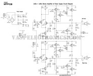
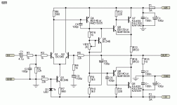
I am attaching both schematics. The OG Rod vs the one I got with my local PCB.
In particular I'm curious about the value difference.
(When I first built this I kept blowing transistors. Then I had a lot of distortion).
All these problems were caused by fake components. The BD139 BD140 and main drivers were fake. One batch just failed. The other had a lot of distortion. No matter how bad the PCB is with the right components. This design just works.
The key areas where there is a huge difference in recommended values.
1. R3 / R39 = 470 ohms on Rods R6/R7=560 Ohms (I used 505.12 Ohms).
2. C2/C4 220uf/47uf on Rods C3/C5 100uf/100uf
3. R11/R12 = 220ohms on Rods R11/R12 100 ohms.
4. BC547 vs BC546 the implications. And I landed up using 2n2222 why because it sounded the best of all the ones I had on hand. Maybe psychological. lol.
There are a few other differences between the two schematics But I want to get to grips and understanding these 3 to start with.
If nobody responds. My backup plan is to just try both options measure noise and power output and just pick the one that sounds better to me. Im just curious were these values changed because they proved to work better or for some other reason.
Attachments
Last edited:
I have that pcb too but not finished yet. Jac is correct. You need HF decoupling caps which is important for stability, otherwise the layout is good. My plan is to use 1uf film +100uf electro (per rail) close to output transistors. On the other hand if you want to use EXOTIC VAS & Driver transistors you need to be cautious using 2SC5200 as outputs because P3A is notorious for instability.
Right now I am testing the CDIL drivers. The toshiba units also worked fine. The unit is stable to absurdly high frequencies.
Im sorry I do not understand C-C-/C+C+
The biggest problem with the vasp board is the absurdly tiny space provided for the Input decoupling cap.
Have a pile full of nice caps to use here but landed up using a 10uf electro because its the only thing that fit.
I want to avoid having parts hanging off the board cause the case will have a see thru top and I want it to look neat and tidy.
The gain seems low to me. And I'm not confident that just changing the feedback resistor is a wise move I would rather increase the gain of each stage by a small amount.
Part of the reason for my low gain issue is because Im not using a pre-amp so rather than add one more board Id like to just increase the gain of each stage.
I love the way my old woodstock 4000 amp works and how he has managed the gain stages.
Would anybody happen to have a schematic for the woodstock amps made in the 80s and 90s out of delhi.
Restoring that amp from the junk yard was a good teacher.
On both rails, near the fuses on Rod's schematics (100n, 100u).Im sorry I do not understand C-C-/C+C+
Because you're using good old BD139/40 as drivers which is my choice too. So good that I end up buying more than 20 pair of ST made 39/40. CDIL is also good & cheap like chips!Right now I am testing the CDIL drivers. The toshiba units also worked fine. The unit is stable to absurdly high frequencies.
Nichicon Muse is a nice choice there! Try it.The biggest problem with the vasp board is the absurdly tiny space provided for the Input decoupling cap.
Have a pile full of nice caps to use here but landed up using a 10uf electro because its the only thing that fit.
I want to avoid having parts hanging off the board cause the case will have a see thru top and I want it to look neat and tidy.
24-27db is a good spot for most power amplifiers.The gain seems low to me. And I'm not confident that just changing the feedback resistor is a wise move I would rather increase the gain of each stage by a small amount.
Use one, no harm in that. OPA134 isn't much noisy.Part of the reason for my low gain issue is because Im not using a pre-amp..
Oh for the C-C-/C+C+ yes I have soldered under the PCB the 100 Nf caps. And also a 10 Nf. Cap.
I learned this trick from my woodstock AMP. He uses these values. He also uses a low ohms resistor after the power caps not sure why but seems to clean up the signal. Maybe this is what people call a snubber resistor. My work on my PSU part hit a wall when I realised my scope cant measure anything under 20mv. I mean the scope shows the same noise at 20mv as when it connected to open air as when its connected to the PSU. Saw a video on how to chk PSU boards down to 1Mv. need to figure that out and use my datsv3 sound card as a sope to measure at these levels.
I have one large huge PSU board with 60,000 uf and all the filter caps. The output from this feeds the P3a and TDA both of which have their own bridge rectifier and 4x 4700 Uf caps. Im not sure if feeding dc to another bridge rectifier and caps will cause any problems if it does I guess Ill just pull the bridge rectifier out bypass it. So far its working fine.
For VAS I have one side on NXP and one side on CDIL. I plan to go all CDIL. Unless I can find something better on my junk yard boards.
I keep trying different parts to see if my friends or my scope can tell the difference.
Today I will be trying some low hfe BC549s which I found in a box from stuff I purchased 25 years ago.
There are 2 companies one all measuere spot on at 200 hfe. And one where they measure from 450-550.
Lets see if it changes the sound.
After this I have some VAS drivers and NPN trans to try from high end audio boards pulled from the junk yard.
I really want to know
The implications of the values.
C2/C4 220uf/47uf vs Rods C3/C5 100uf/100uf
R11/R12 = 220ohms on Rods R11/R12 100 ohms.
Ps: Chat GTP has some interesting things to say on boot strap cap values and their implications.
For the pre-amp and RIAA I plan to use
Arylic BP50 Bluetooth Preamp. It saves me the headache of building a RIAA circuit. And gives me good bluetooth.
On testing exotic caps I have found no difference on the datsv3 between the most basic electors and fancy names.
I will ask around in the local market if anybody has some backdoor muse caps.
Today I plan to build in all the differences so I can compare channels and the impact they have. I have found lower Uf feedback caps tend to have more clarity.
I have one tip on the VASP board. Put the jumpers on the underside or insulate them else when you go to set the bias you will short the jumper and the -Ve rail. And blow all your transistors. Ask how i know lol.
What is the best way to compare changes.
Say I found some good VAS drivers form a high end amp. The specs show i can replace the BD139/140
I replace them on one side.
Now I listen to the music.
Presently the system is limited to asking friends which side sounds better in a blind test and looking at FFT numbers on the scope. There has to be a better way.
What else can I do.
Like how about I put one channel on input and one on output and do a CH1-CH2 to see what I get. Maybe see which side is more true to input signal ?.
What about i put CH1 to Right and CH2 to Left and again do a CH1-CH2 and see
My scope usage has been very limited to testing and trouble shooting an automotive circuit I do. So no idea about audio.
I don’t agree with the way this is described. The P3a is a proven stable design with the parts Rod recommends. But the output stage is more sensitive to parts selection than an EF2 topology. If you use parts other than what Rod recommends, you may need to do some tuning. The drivers in particular are sensitive if modern fast output devices are used.On the other hand if you want to use EXOTIC VAS & Driver transistors you need to be cautious using 2SC5200 as outputs because P3A is notorious for instability.
Ok since I haven't got both spice modells up and running. Or the info on what to test for other than noise. Ill just report the findings I got from making changes.
1. On the caps Rods values worked better.
2. R11/R12 = 220ohms on Rods R11/R12 100 ohms. On this 220 ohms seems to be working better.
But did notice that with Rods values the Bias settings seem to be less stable and noisy. Noticed that I had to have different settings on the trim pot to bias both sides.
So thought hum lets hook up the scope and see what i'm getting across the two resistors.
Everybody talks about setting the bias using a simple meter. Nobody talks about what that signal looks like on the scope.
I found that one of the bias signals had more noise than the other. Need to spend more time observing this.
Stabilizing the Bias tends to trigger my OCD. Yes I know if the heat sink is large enough it will eventually stabilize itself.
But Im seeing noise on this even when the values have stabilized. No matter what I set it to 50mv or 150mv.
Anybody willing to give some inputs on why the bias signal looks stable on one side. And has a lot of noise on the other ?.
In other news I got my first DAC. My friends say they are fed up of listening to my crappy chinese bluetooth module. Im hoping this will help give me a cleaner signal into my amps for testing. In the past I have been using my Samsung Note 9 audio jack with a function generator app. Lets see if this DAC can beat the one on the Note 9. In terms of noise and clarity.
Funny on the TDA board. I just went from the stock 22u to 47u back to 22u wondering if what your saying is specific to this amps design or it applies to all amps. I've spent time on chat gtp trying to grasp the role the cap plays in the bootstrap circuit. And how to pick the optimum value. Need to give it time. Im old. And only a year into this hobby.47u is too low for the bootstrap cap. It will increase low frequency distortion. Use at least 100u, or 220 if you can fit it.
The switch from 1 LED to 2 diode biasing for the Q3 CCS doesn't make sense to me. Without a filtering cap on the midpoint of ground resistor, the PSSR of a LED is superior to 2 diodes. Douglas Self has stats on this in his Power Amplifier design book; -65dB for 2 diodes and -77 dB for LED. If a decoupling cap is used (split R18 into 2 10K resistors and filter the midpoint with a 47uF cap), PSSR increases to -87 dB.
Thanks for that tip one less thing for me to test.
Right now Im still stuck studying the signal between the bias resistors. Why one side is more stable than the other with less noise. Has anybody scoped out their Bias resistors. Or do they just measure voltage and call it a day.
Could not find any info on this subject.
After that I have 3 configurations to try pertaining to the bootstrap and feedback cap values. There seem to be huge variations between the 3.
This is how I learn not trying to reinvent the wheel. If I do land up making a new PCB just about the only thing I would add would be speaker protection. For now I have a separate PCB for startup delay and speaker protection.
- Home
- Amplifiers
- Solid State
- Comparing P3A Schematics