Free Direct Drive Electrostatic Speakers

With a covering, they could have a marginal spouse approval factor. Allegedly they sound great. I have no time to mess with these.

A good friend knows their history and how to properly drive them. He can provide an amp design.

These were the final iteration of the design by a deceased gentleman who was determined to build them out of common building materials. I heard an earlier, smaller version of the speakers (we even displayed them one year at The Capital Audiofest). They are incredibly detailed, but no deep bass.

They are ENORMOUS! 48" wide and 54" tall.

Located in Maryland, near DC, they MUST go. I may be able to help transport them, to a point. I hate the notion of putting them in a dumpster, but they have to go.

Stuart

Attachments

  • 20240723_123806.jpg
    20240723_123806.jpg
    474.8 KB · Views: 106
  • 20240723_123813.jpg
    20240723_123813.jpg
    903.8 KB · Views: 103
  • 20240723_123824.jpg
    20240723_123824.jpg
    333.5 KB · Views: 107

3 way XO help

A few of us have been discussing this 3 way XO in another thread. I am having a lot of trouble with the phase alignment between the woofer and the mid. I will post up what I have so far, all the files, and pertinent information.

The tweeter and woofer measurements were taken at the same y hieght of 675mm and the woofer was taken at its y height of 380mm

If anyone wants to take whack it, feel free to do so. This is my first proper 3 way crossover that has off axis design taken into consideration.

The z offset should be taken care of in the measurements.
The woofer is ported and the port and woofer have already been summated, merged nearfield with the far field, and diffraction applied to the near field.
The same goes for the mid.
The tweeter measurements are raw far field so the diffraction is built in.

I very much appreciate the help. I think it is very helpful to see other's crossover designs compared to mine to see what others do.
Thanks to SONCE, CABIRIO, A4E, and MARKBAKK for all they help they have given me so far.

Attachments

For Sale WO24P-4, KEF R100, SB17CAC35-4, Textronix 2235 100MHz Oscilloscope, Peerless 12" XXLS 830845

Selling some unused components and device from my dipole speaker project.

1. a pair of SB Acoustics WO24P-4
Condition: very good

I buy those for using as lower mid (100-500Hz) in my dipole speaker since 2023. Now I have better driver for this task (26W/4867), so those two must go
status: sold

2. a pair of SB Acoustics SB17CAC35-4
Condition: very good
Status: Sold

3. a pair of Peerless 12" XXLS 830845 subwoofer
Condition: good
Status: Sold

4. KEF R100
Condition: Like new
I use it only as surround speaker, and have plan to build a cardioid speaker with coax driver from this speaker. But after Munich Highend, I decide to design an horn speaker instead, so these speaker need to go to fund for this project.
Status: sold


5. Textronix 2235 100Mhz Analog Oscilloscope with accessories
Condition: Very good. I use it for checking solid state amplifier, but now I have a nice Siglent DSO.
Status: Sold

Attachments

  • 2235.jpg
    2235.jpg
    381.4 KB · Views: 140
  • KEFR100-2.jpg
    KEFR100-2.jpg
    177.9 KB · Views: 130
  • WO24P-3.jpg
    WO24P-3.jpg
    243.2 KB · Views: 95
  • WO24P-2.jpg
    WO24P-2.jpg
    370.9 KB · Views: 96
  • WO24P-1.jpg
    WO24P-1.jpg
    497.6 KB · Views: 102
  • kefr100.jpg
    kefr100.jpg
    317.6 KB · Views: 133

Sub tuning, you favorite house curve

I think something that is not often written about, is how to best tune sub. What I mean is not in room response, but the actual curve of the sub. Or in plain words how the sub rolls of.

With active filtering and Linkwitz Transform and sealed cabinet, we can pretty much do what we like. In reality no, if you don’t have a lot of watts on tap. And boosting to much we might run into digital clipping.

In the extreme we have flat line to 20 hz then gradual roll of from there. I guess with typical corner placement, and only one sub in the chain, that will in room give too big of a hump.

In the other spectrum we could have Qtc of 0.5 with gradual roll off from 100 hz and below.


In your experience what works best. Do you have a preference?

DIY optical cartridge preamp

DS Audio recently decided to open up their optical phono stage details for the world to use in order to help optical cartridges become more widely used and compatible with more preamps, etc., rather than only being compatible with DS Audio phono stages.

My first thought was that this could open up the possibility of a DS Audio cartridge + DIY optical phono preamp 🙂

Some info is published here: https://www.ds-audio-w.biz/wp-content/uploads/2021/03/EQ-infover1.02.pdf

According to this article, DS Audio is open to technical enquiries about their technology, though this may apply to manufacturers only: DS Audio is sharing its optical phono cartridge secrets for free | What Hi-Fi?


Who wants to go first? 😀

For Sale Verum 1 MKII Headphones Zebrano Brown + silver

Hi,

For sale is a brand new pair of Verum 1 MKII Headphones, the Zebrano (Brown + silver) version. Only a few hours of use, only to find out I'm not a planar magnetic type fan. I personally prefer the old driver style such as Senn 650.

Bought them on a wait list at GR Research and got them recently
Verum 1 MKII Headphones

If you're interested, I still have the original box it was shipped in, will just need to find a shipping box to put that one in.

Retail price is Sold but out of stock. I would let them go for Sold + shipping OBO

Thanks
Do

Attachments

  • 2024-06-09 10.51.29.jpg
    2024-06-09 10.51.29.jpg
    250 KB · Views: 126
  • 2024-06-09 10.51.37.jpg
    2024-06-09 10.51.37.jpg
    199.6 KB · Views: 131
  • 2024-06-09 10.51.56.jpg
    2024-06-09 10.51.56.jpg
    250.1 KB · Views: 134
  • 2024-06-09 10.52.07.jpg
    2024-06-09 10.52.07.jpg
    195 KB · Views: 123
  • 2024-06-09 10.52.13.jpg
    2024-06-09 10.52.13.jpg
    202.9 KB · Views: 120
  • 2024-06-09 10.52.32.jpg
    2024-06-09 10.52.32.jpg
    255.8 KB · Views: 123
  • Like
Reactions: poseidonsvoice

For Sale UK - Neurochrome 686 - all boards - fully assembled and working

Neurochrome 686 fully assembled

All working as it should, no power on/off thumps just the quiet clicks from the relays

Case Dimensions in mm (approx)
450 wide v 410 deep x 190 high
Note: the sockets and switch add depth so allowing for cables etc front to rear depth in use is about 490mm

The Amplifier Includes:

2 x Neurochrome Modulus 686 boards
2 x Neurochrome Power supply boards – one for each channel, 88000uf per channel
1 x Neurochrome Intelligent Soft Start
2 x Neurochrome Guardian speaker protection – one for each channel
Green Ground/Earth Socket on rear
XLR inputs
4mm Speaker terminals

1 x Mains Transformer 800 watt with separate windings for each channel.

  • 2 x 400 watts windings @ 25vac
  • One winding for each channel
IMG_20240718_120756.jpgPXL_20240718_110644971.jpgIMG_20240718_120717.jpgIMG_20240718_122422.jpgIMG_20240718_122417.jpgIMG_20240718_122436.jpgIMG_20240718_122432.jpg

£2000 firm

Attachments

  • IMG_20240718_120709.jpg
    IMG_20240718_120709.jpg
    409.1 KB · Views: 111
  • IMG_20240718_122428.jpg
    IMG_20240718_122428.jpg
    503.8 KB · Views: 108

For Sale London UK: 2A3 SE amplifier, premium parts

For sale - my 2a3 SE amplifier with state of the art power supply - big Hammond transformer and choke, GZ34 rectifier, Black Gate bypass caps on the 2a3.

Input section is a 6N1P with teflon coupling caps, Kemet DC Link bypasses and Holco resistors. All premium parts.

Configured right now as just an amplifier but I can add a selector and volume control as needed to make it integrated.

Asking £485 excluding 2a3 valves. REDUCED to £460 including nearly new Sovtek 2a3s.

Situated Kensington, London. Auditions welcome. PM me with any questions.

jimsamp1.jpgjimsamp2.jpg

BrianGT 3886 kit documents

A 3886 kit I built about a decade ago smoked a 3886 chip. I set it aside and moved on to others, but recently was re-inspired to play with high currents and audio. I would like to re-build the amp with a replaced 3886 chip, but I cannot find the schematic, parts list, or build instructions for the BrianGT 3886 kit.

Does anyone here (or anywhere else?) have those documents as .pdfs they could send me?

JBL 2360 horn - Shape of entry

Hi all,

I have two JBL 2360 horns, and in the (near) future I want to purchase 2 CD's for them. What strikes me is the shape of the 2" horn entry, see the image below. It is certainly not circular (top to bottom: ~51mm, left to right ~47mm). Both of them look the same. Seeing this got me thinking: is it worth to invest in 600 euro drivers like the BMS or B&C coaxials for this horn? It feels a bit like using a highly advanced tight toleranced driver attached to a horn of the 'olden day's'. (Don't know what I get myself into by saying this) 🙂

Hopefully some of you can share their experience with this horn and/or give some insight of the effect of coupling a perfect circular 2" CD to this horn entry.

Thanks!

IMG_1190.JPG

Build STK8050 equivalent

Hi,

A friend got me his two Technics SU-V4 amps, both have failed STK modules. I've been reading a lot of bad stuff about those and even worse about the modern counterfeit ones you can buy of a lot of sites.
He really wants to save his amps and I was wondering if it wouldn't be possible to build an equivalent to the modules circuit with discrete components. It seems to have been done for other references (stk-0050 is one of them I believe).
Is it possible to just copy the schematic of the internal circuitry of the stk by using discrete components that can handle a lot more to prevent getting the same problems all over again ?

Best Subwoofer Driver to hit below 20Hz(Sealed) under $500

I am looking for Subwoofer Driver 15" or 18" that could hit below 20Hz in sealed GSG BTS Sealed enclosure(4.75cuft). What would be some good and reliable options under $500. I was considering drivers from Dayton Audio but heard that lately they been having a lot of QC and reliability issues over time. What other options are there. That could go below 20hz. Will be used for theater setup.

Vintage NAD 3020 amplifier history and simulation in LTSpice with possible simple improvements

NAD 3020

The NAD 3020 amplifier, introduced in 1978 by New Acoustic Dimension (NAD), is a landmark in hi-fi audio history. Designed by Bjørn Erik Edvardsen, the NAD 3020 was a game-changer, challenging the notion that high-quality sound required a significant financial investment. At the time, the audio market was dominated by expensive, high-powered amplifiers. The NAD 3020, with its modest price and minimalist design, revolutionized the landscape by offering exceptional sound quality to a broader audience.

The NAD 3020 quickly gained a reputation for its remarkable performance. Despite its modest power rating of 20 watts per channel, it delivered much higher dynamic headroom, allowing it to handle musical peaks with impressive clarity and power. This capability enabled the amplifier to compete with higher-powered models, providing an audio experience that defied its wattage. Another key feature was its high current capability, crucial for driving difficult speaker loads and controlling speaker cones with precision. This resulted in detailed and accurate sound reproduction, making the NAD 3020 suitable for a wide range of speakers and musical genres.

A significant draw for vinyl enthusiasts was the integrated high-quality phono stage, which allowed turntables to be connected directly to the amplifier, offering a warm and rich analog sound without the need for an external phono preamp. The design simplicity of the NAD 3020, both externally and internally, contributed to its superior performance. By keeping the signal path clean and using high-quality components where it mattered most, NAD ensured the amplifier could deliver pure and uncolored sound, enhancing its reliability and longevity.

The most celebrated aspect of the NAD 3020's sound was its musicality and warmth. Renowned for its ability to reproduce music with a sense of rhythm and timing, it made listening enjoyable and engaging. Its warm sound signature added richness to the audio, making it a favorite among audiophiles and casual listeners alike. The NAD 3020 remains an iconic piece of audio equipment, revered for its groundbreaking approach to sound quality and affordability. Its unique blend of power, high current capability, and musical warmth set it apart from other amplifiers of its time, contributing to its legendary status. Decades after its introduction, the NAD 3020 continues to inspire and influence modern amplifier design, cementing its place in the annals of hi-fi history.
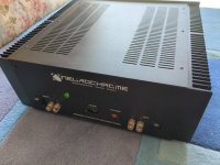
NAD 2150

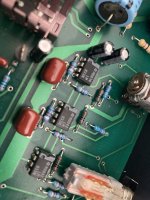
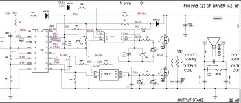
The NAD 2150 amplifier, introduced in the early 1980s, is part of NAD's legacy of producing high-quality, affordable audio equipment. It employs the same foundational design concepts that made the NAD 3020 a legend in the audio world. Both amplifiers feature a singleton input stage with a constant current source, which ensures stable and low-noise operation. Next stage - VAS (voltage amplification stage) is using complimentary feedback transistor pair, which enhances linearity and reduces distortion, allowing for a more accurate and musical sound reproduction. And finally, both models utilize an emitter follower class AB output stage, providing a balanced mix of efficiency and sound quality.

nad2150amp-sch.PNG

However, a significant enhancement in the NAD 2150 is its use of higher current capability output transistors. These transistors enable the 2150 to drive more demanding speaker loads with greater control and robustness, resulting in improved performance, especially with contemporary, power-hungry speakers.

Another notable difference between the NAD 2150 and its predecessor is the absence of the preamp section in the 2150. While the NAD 3020 included a preamp, making it a versatile all-in-one solution, the 2150's omission of this section makes it particularly well-suited for modern audio setups. This design choice allows users to feed the signal directly from modern DACs and other high-quality sources without the additional signal path introduced by an integrated preamp. As a result, the NAD 2150 can offer a purer and more direct signal, aligning perfectly with the preferences of today's audiophiles who often favor streamlined, minimalistic systems for the highest fidelity audio reproduction.

Singelton input stage

The singleton input stage, as utilized in amplifiers like the NAD 3020, offers distinct advantages that contribute to its enduring appeal in audio design. Unlike the differential pair, which typically involves two transistors, the singleton input stage simplifies the circuitry. This simplicity often results in lower overall noise and distortion levels, crucial for preserving the fidelity of audio signals. Additionally, the singleton configuration can offer better phase accuracy and transient response, allowing for a more accurate portrayal of the original audio waveform. These characteristics make the singleton input stage particularly well-suited for applications where high-fidelity reproduction and transparency are paramount.

However, it's essential to acknowledge that the singleton input stage has drawbacks compared to the differential pair. One notable limitation is its typically lower common-mode rejection ratio (CMRR) compared to differential configurations. This means it may be more susceptible to common-mode noise and interference, potentially impacting signal quality in environments with electrical noise. Additionally, the thermal stability and matching characteristics of the singleton input stage may not be as robust as those of differential pairs, which can affect performance consistency over varying operating conditions.

Despite these considerations, the NAD 3020 amplifier's historical success and revered sound quality stand as testament to the effectiveness of the singleton input stage when implemented with careful design considerations. The 3020's ability to deliver clean, natural sound with minimal coloration has solidified its place in audio history and continues to influence modern amplifier designs. Its enduring popularity underscores the viability and effectiveness of the singleton input stage in achieving high-quality audio reproduction, showcasing its strengths in the context of critical listening environments and audiophile preferences.

My story

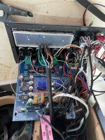
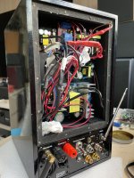
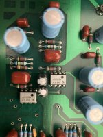
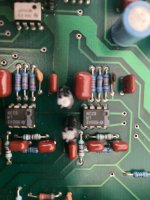
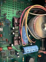
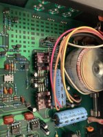
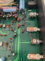
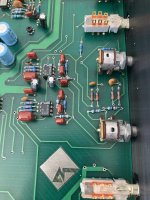
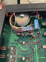
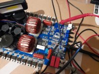
After immersing myself in the rich history and technical details of vintage hi-fi equipment, particularly the NAD 3020 and its successor, the NAD 2150, I decided to delve deeper into this world by acquiring a NAD 2150 amplifier.

nad2150-front.PNG

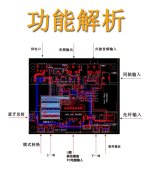
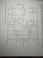
Intrigued by its renowned design principles I sought to explore its inner workings further. I obtained the service manual, complete with schematics, and delved into understanding how these components interact to produce the amplifier's distinctive sound.

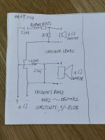
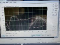
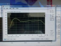
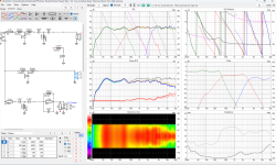
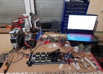
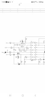
Driven by curiosity and a passion for electronics, I took my exploration a step further by simulating the NAD 2150's circuit layout using LTSpice, a circuit simulation software. This exercise not only deepened my understanding of amplifier design but also allowed me to visualize how different components contribute to its overall performance. Sketching the circuit in LTSpice was both educational and enjoyable, providing insights into the amplifier's behavior under various conditions.

nad2150amp-sch-sim.PNG

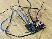
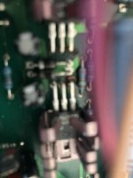
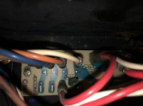
For those brave enough to open the amp and solder a few capacitors a significant improvement can be made by swapping input filter capacitors to 22uF + 22uF and DC coupling capacitor to 4700uF resulting in 0.002% THD@1kHz.

Attachments

Hello!

Hello everyone!

I've always been passionate about music (just listening) and recently I began to be more interested in the equipment aspect to enjoy it more and better.
I started by making my own speakers, a version of the 'Overnight Sensations' by Paul Carmody. I tried them only with a class D amplifier and the first listening experience was incredible. From there I acquired an old Kendwood KA-300 amplifier in very good condition and again, the experience was better than the previous one and the loudness function helped a lot to better balance the sound of the speakers since I usually listen to them in a very small environment.

I'm really enjoying this journey of baby steps improvements😅 so I hope to continue improving my equipment and creating new ones.

Thanks for reading!

IMG_1980.JPEG

Technics SL-Q303: Unstable speed above 33.3 RPM

Hi All,

Looking for help troubleshooting the following issue that occurred after I replaced the electrolytic capacitors. Another reminder of the adage if it aint broken, don't fix it🙂
I am afraid I may have damaged IC201 or IC202. The only tool I have is a DMM.

After replacing the electrolytic capacitors on the driver board:

33.3RPM is working fine. If I spin the platter little bit faster than 33.3RPM the speed control becomes unstable and seems to oscillate a steady frequency. The issue clears after stopping the platter.
Switching to 45 RPM causes the same issue of course, and switching back to 33.3RPM will not clear the issue. I verified 3.4V/4.0V on the speed switch 33/45rpm per service manual which is attached. I figure there's something wrong with the rotation sensor circuit. Thanks for reading and any help is appreciated.

Attachments

Audio (Lateral) MOSFET's for Class AB - Overview, P-Spice URL's

Audio (Lateral) MOSFET's for Class AB - Overview concerning Types and some URL's (also for various P-Spice Parameter)

Not listed here are the IRF/IRFP/IRL and IRF related types, because this types actually appropriate only for class-D and pure class-A, but not for class AB push pull with 100-200 mA idle current.

1) Hitachi/Renesas vintage versions
2SK133/2SJ48 (TO3)
2SK134/2SJ49 (TO3)
2SK135/2SJ50 (TO3)
2SK226/2SJ81 (H-PAK identical to 2SK133/2SJ48)
2SK227/2SJ82 (H-PAK identical to 2SK134/2SJ49)
2SK228/2SJ83 (H-PAK identical to 2SK135/2SJ50)
2SK175/2SJ55
2SK176/2SJ56
2SK343/2SJ99 (H-PAK)
2SK344/2SJ100 (H-PAK)
2SK345/2SJ101 (TO-220)
2SK346/2SJ102 (TO-220)
Datasheets
2SK134 pdf, 2SK134 description, 2SK134 datasheets, 2SK134 view ::: ALLDATASHEET :::
2SK134 Datasheet pdf - LOW FREQUENCY POWER AMPLIFIER - Hitachi Semiconductor
2SJ48 Datasheet pdf - LOW FREQUENCY POWER AMPLIFIER - Hitachi Semiconductor
2SK226 datasheet pdf datenblatt - Hitachi Semiconductor - SILICON N-CHANNEL ENHANCEMENT MOSFET ::: ALLDATASHEET :::
2SK176 datasheet and Application Note, Data Sheet, Circuit, PDF, Pinout | Datasheet Archive
2SJ56 2SJ55
2SK343 datasheet and Application Note, Data Sheet, Circuit, PDF, Pinout | Datasheet Archive
2SK345 datasheet and Application Note, Data Sheet, Circuit, PDF, Pinout | Datasheet Archive
Replacement/Substitude advices
ECX10P20 / ECX10N20 EXICON �iƒ‚�[ƒ‹ƒhƒ^ƒCƒv�j| ƒnƒCƒGƒ“ƒhƒI�[ƒfƒBƒI
http://www.diyaudio.com/forums/solid-state/40439-new-member-replacing-2sk133-135-2sj48-50-a.html
http://www.diyaudio.com/forums/solid-state/58719-sub-2sj50-2sk135.html
http://www.diyaudio.com/forums/swap-meet/8531-i-need-2sk135-2sj50.html
http://www.diyaudio.com/forums/solid-state/47475-substitute-2sj55-2sk175-vmos-fet-s.html (Swiss Physics Model 6)
http://www.diyaudio.com/forums/swap-meet/55180-wanted-2sk176-2sj56.html
http://www.diyaudio.com/forums/solid-state/147700-substitute-2sk134-2sj49-2sk176-2sj56.html
http://www.diyaudio.com/forums/solid-state/108565-musical-fidelity-p170-blown-transistors.html
http://www.diyaudio.com/forums/solid-state/81654-vintage-mosfets.html (MF, A370)
http://www.diyaudio.com/forums/solid-state/45715-myst-tma3-transistors-hitachi-2sk226-2sj82.html (Myst TMA3)
http://www.diyaudio.com/forums/parts/121984-need-2sk225-2sj81-fets-sugden-amp-help.html
http://www.diyaudio.com/forums/parts/43030-2sj81-2sk255-help-identify.html
http://www.diyaudio.com/forums/solid-state/4094-lateral-mosfet-replacements-2sk1058-hitachi.html
http://www.diyaudio.com/forums/solid-state/37813-lateral-structure-mosfet.html (2SK1058/BUZ900)
http://www.diyaudio.com/forums/parts/99732-looking-find-2sk343-2sj99-mosfet.html
http://www.diyaudio.com/forums/solid-state/1449-mosfet-replacement.html (2SK/2SJ - ECX cross ref - post #4)
Offers (for sale)
http://www.diyaudio.com/forums/swap-meet/91344-fs-2sk133.html
http://www.diyaudio.com/forums/swap...orsetrade-my-hitachi-laterals-your-irfps.html
http://www.diyaudio.com/forums/swap-meet/158227-original-2sk343-2sj99-mosfets-140v-8a-sale.html
http://www.diyaudio.com/forums/swap-meet/100410-opa549t-2sk343-2sj99-kef.html
http://www.diyaudio.com/forums/parts/147078-2sk343-2sj99-audio-mosfets-140v-8a.html
‰�”N‚Ì‚c‚bƒAƒ“ƒvƒp�[ƒc�iƒpƒ��[�E‚e‚d‚s�j
http://www.diyaudio.com/forums/solid-state/166647-where-find-those-mosfets.html
Hitachi HMA Series, Schematics
http://www.diyaudio.com/forums/solid-state/162763-hitach-lateral-mosfets-back-march-1978-a.html
Various Schematics and replacement hints
http://www.diyaudio.com/forums/solid-state/1188-2sj49-2sk134.html
6922 driving
http://www.diyaudio.com/forums/solid-state/35848-when-6922-married-2sj49-2sk134.html
2SK135 Serial Regulator schema
http://www.diyaudio.com/forums/parts/139615-fet-help-please-2sk135.html
Hafler MOSFET checker
http://www.diyaudio.com/forums/swap-meet/58888-mosfets-xl-280-p-230-etc-natched.html#post660932
Idle current values
http://www.diyaudio.com/forums/parts/13094-2sk135-2sj50.html
Albs DacMos and schema example
http://www.diyaudio.com/forums/solid-state/19448-amp-2sj56-2sk176.html
Ampslab IM60-LM60
http://www.diyaudio.com/forums/solid-state/127297-hitachi-mosfet-power-amplifier.html
How long it survived
http://www.diyaudio.com/forums/solid-state/111116-lateral-mosfet-torture.html (2SJ50/2SJ83)

2) Hitachi/Renesas newer versions
2SK1056/2SJ160 (TOP-3)
2SK1057/2SJ161 (TOP-3)
2SK1058/2SJ162 (TOP-3, most popular)
2SK2220/2SJ351 (TOP-3)
2SK2221/2SJ352 (TOP-3)
Datasheet
http://documentation.renesas.com/eng/products/transistor/rej03g0906_2sk1056ds.pdf
http://documentation.renesas.com/eng/products/transistor/rej03g1004_2sk2220ds.pdf
http://www.datasheetcatalog.org/datasheet/HitachiSemiconductor/mXwuzrz.pdf
Power MOSFETs for General Amplifier
Power MOSFETs for General Amplifier | Renesas Electronics America
Plantefeve MOS-FET 2 x 30 W
http://www.diyaudio.com/forums/solid-state/74080-30w-mosfet-plantefeve.html
Ideal quiescent current
http://www.diyaudio.com/forums/solid-state/31420-what-quiescent-current-hitachi-2sk1058-2sj162.html
Replacement/Substitude advices
http://www.diyaudio.com/forums/solid-state/4094-lateral-mosfet-replacements-2sk1058-hitachi.html
Difference between a lateral MOSFETS and vertical MOSFETS
http://www.diyaudio.com/forums/solid-state/162453-renesas-hitachi-2sk1058-2sj162-lateral-mosfet.html
Amp Project 2SK1058
http://www.diyaudio.com/forums/solid-state/170502-2sk1058-mosfet-amp.html
http://www.diyaudio.com/forums/solid-state/65789-poweramp-2sk1058-2sj162.html
http://www.diyaudio.com/forums/solid-state/28083-holtons-lateral-amp.html (2SK1058/2SJ62)
Aussie Amplifiers
LM4702 Driving a MOSFET Output Stage /LM49830TB Ultra High Fidelity Ref Design AN1645-AN1850
http://www.diyaudio.com/forums/solid-state/140715-lateral-mosfet-thermal-vs-others.html (2SK1058)

3) Toshiba
2SK405/2SJ415 (TOP-3)
2SK1529/2SJ200
2SK1530/2SJ201 (TO-3P(L)/2-21F1B)
2SK3497/2SJ618 (2-16C1B, new type, datasheet from 2009)
Datasheets
2SK405 pdf, 2SK405 description, 2SK405 datasheets, 2SK405 view ::: ALLDATASHEET :::
http://www.audiolabga.com/pdf/2SK1529.pdf
????????????????????????????????
http://www.schuro.de/Daten/Japanhalbleiter/2SK1530.pdf
????????????????????????????????
http://www.toshiba.com/taec/components2/Datasheet_Sync//74/2868.pdf
Replacement/Substitude advices
http://www.diyaudio.com/forums/solid-state/80455-2sk405-3sk1529-2sk1530.html
http://www.diyaudio.com/forums/parts/166715-2sk1530-2sj201.html
Offers
http://www.diyaudio.com/forums/parts/134239-wanted-2sk405-2sj115.html
http://www.diyaudio.com/forums/solid-state/131646-matched-2sk1530-2sj201.html
Alaskan Audio 1R1 schematic/PCB
http://www.diyaudio.com/forums/soli...sk1530-pair-mosfet-suitable-output-stage.html
Elektuur Crescendo
http://www.diyaudio.com/forums/solid-state/23116-whats-wrong-those-mosfets.html (2SK1530/2SJ201)
http://www.diyaudio.com/forums/solid-state/73460-crescendo-amp.html
http://www.diyaudio.com/forums/solid-state/58661-help-crescendo-me.html
Reporting about sonic quality
http://www.diyaudio.com/forums/solid-state/165116-best-audio-power-mosfet.html (2SK3911)
Testing (THD curves)
http://www.diyaudio.com/forums/soli...er-mosfets-2sk3497-2sj618-little-testing.html

4) Magnatec/Semelab
BUZ901/BUZ906 (vintage type)
BUZ900/BUZ905 (vintage type)
ALF08N16V/ALF08P16V (new)
ALF08N20V/ALF08P20V (new)
Datasheets
http://www.bonavolta.ch/hobby/files/BUZ900.pdf
Magnatec. ALFET Lateral MOSFETs
http://web.archive.org/web/20030205164841/http://www.magnatec-uk.co.uk/mosdata.shtml
http://www.semelab.com/pdf/acc.pdf
http://www.semelab.com/pdf/magnatec/ALF08N16V ALF08N20V.pdf
http://www.semelab.com/pdf/magnatec/ALF08P16V ALF08P20V.pdf
Inductance Value
http://www.diyaudio.com/forums/solid-state/82122-inductance-required-buz900-23k135.html
Basic Character discuss
http://www.diyaudio.com/forums/pass-labs/24658-buz900-series-mosfets.html
Tube driving amp
http://www.diyaudio.com/forums/solid-state/154795-hybrid-buz900.html
Best Audio MOSFET
http://www.diyaudio.com/forums/solid-state/165116-best-audio-power-mosfet.html
New Magnatec Line
http://www.diyaudio.com/forums/solid-state/154482-magnatecs-new-line-alfet.html
Offers
http://www.diyaudio.com/forums/swap-meet/162884-buz900-buz905-mosfets.html
http://www.diyaudio.com/forums/swap-meet/165661-i-look-buz901-buz906.html
http://www.diyaudio.com/forums/swap-meet/86556-fs-16-pieces-buz901-buz905.html
http://www.diyaudio.com/forums/swap-meet/70452-wanted-buz901-906p-mosfets.html
http://www.diyaudio.com/forums/solid-state/70383-us-source-buz901-906-a.html
http://www.diyaudio.com/forums/swap-meet/148182-buz901dp-lateral-mosfet-wanted.html
V-GS spread
http://www.diyaudio.com/forums/solid-state/148213-genuine-buz901-906-not.html
Experiences
http://www.diyaudio.com/forums/solid-state/18796-audio-mosfet-transistor.html (BUZ900DP BUZ901DP)
Comparsion
http://www.diyaudio.com/forums/solid-state/109183-exicon-10n16-10p16-vs-magnatec-buz900-905-a.html
Replacements
http://www.diyaudio.com/forums/parts/103278-possible-replacement-buz901p-buz905-6p.html

5) Exicon vintage versions
ECX10N16/ECX10P16
ECX10N20/ECX10P20
Datasheet
ECX10N20
ECX10P20
Replacements
ECX10P20 / ECX10N20 EXICON �iƒ‚�[ƒ‹ƒhƒ^ƒCƒv�j| ƒnƒCƒGƒ“ƒhƒI�[ƒfƒBƒI
2SK/2SJ - ECX cross ref - post #4
http://www.diyaudio.com/forums/solid-state/1449-mosfet-replacement.html
Various
http://www.diyaudio.com/forums/solid-state/133560-my-exicon-amp-project.html
http://www.diyaudio.com/forums/solid-state/137674-2a-classa-using-exicon-lateral.html
http://www.diyaudio.com/forums/solid-state/476-exicon-mosfet-eval-amps.html
http://www.diyaudio.com/forums/solid-state/1238-exicon-mosfets.html

6) First Generation Power MOSFET's (V-FET's)
http://www.diyaudio.com/forums/chip-amps/157618-vfet-hitachi-2sk77-2sk76-2sj26.html
http://www.diyaudio.com/forums/solid-state/74774-2sk77.html
http://www.diyaudio.com/forums/soli...to3-like-yamaha-2sk77-nec-2d363-overview.html
http://www.diyaudio.com/forums/soli...kin-2sj28-2sj18-2sk60-2sj26-2sk76-2sk180.html
http://www.diyaudio.com/forums/swap-meet/109664-wtb-2sk60-2sj18.html

7) URL's about P-Spice Parameter
if you have good models for the 2SK1058/2SJ162, then you have good models for the 2SK135/2SJ50
http://www.diyaudio.com/forums/solid-state/31131-hafler-dh-200-220-mods-22.html ( post #217)
http://www.diyaudio.com/forums/solid-state/162763-hitach-lateral-mosfets-back-march-1978-a.html
http://www.diyaudio.com/forums/parts/3230-p-spice-models-4-2sk1058-2sj162.html#post998418 (2SK1058 and 2SJ162)
http://www.diyaudio.com/forums/solid-state/4094-lateral-mosfet-replacements-2sk1058-hitachi-2.html
‚o‚r‚�‚‰‚ƒ‚…�i•]‰¿”Å�j‚Å“d’rޮЮ‘S‘Î�ÌŒ^ƒpƒ��[ƒAƒ“ƒv‚ðƒVƒ~ƒ…ƒŒ�[ƒg‚·‚é�@‚»‚Ì‚Q (Curves)
http://www.diyaudio.com/forums/solid-state/2969-spice-models-2.html#post26926 (post #16 2SK1058 and 2SJ162)
http://www.diyaudio.com/forums/solid-state/31338-exicon-10p20-10n20-pspice-model.html (post #1)
http://www.diyaudio.com/forums/parts/68163-spice-model-2sk1529.html#post2254795 (2SK1529/2SK1530
Models for Multisim Stuff you won (interactice design tools)
http://www.diyaudio.com/forums/soli...0-471-472-vs-mje340-350-better.html#post34113
http://www.diyaudio.com/forums/solid-state/28633-single-ended-mosfet-amp.html#post331880 (2SK1058 and 2SJ162)
http://www.diyaudio.com/forums/solid-state/74089-spice-models-exicon-mosfets.html
http://www.diyaudio.com/forums/solid-state/22756-looking-lateral-mosfet-spice-models.html
BUZ Spice models and data
http://www.diyaudio.com/forums/solid-state/2969-spice-models-2.html#post27088

8) Various URL's
http://www.diyaudio.com/forums/solid-state/70968-replace-irf-lateral-mosfet.html
http://www.diyaudio.com/forums/pass-labs/51643-lateral-vs-vertical-p-vs-n.html
http://www.diyaudio.com/forums/solid-state/17184-lateral-mosfets-why.html
http://www.diyaudio.com/forums/solid-state/28853-sound-vmosfet.html?perpage=10&pagenumber=1

Who knows more currently produced lateral MOSFET's for replace vintage types?

Adcom GFA545 II service manual

Hi ,
Anyone got a copy of GFA545 II amp service manual?
I am planning to take the amp to Europe and like to require the transformer primary if possible.
The power distribution board inside shows 220V and pins and primary has two sets of wires , so I am pretty sure it could be rewired.
Thanks.

Attachments

  • BDA68A6E-BBF6-4F6E-A76B-DDACE5670F09.jpeg
    BDA68A6E-BBF6-4F6E-A76B-DDACE5670F09.jpeg
    188.6 KB · Views: 154

2017 VFET kit - 2ea 2SK82/2SJ28 - SOLD

I'm selling the kit I purchased back in 2017 with matched VFETs and circuit board. I REALLY want to build the amp but I just don't see it happening any time soon and would like to pass it on to someone who will actually put them to good use. Purchased direct from diyaudiostore. Thanks for looking!

Edit: forgot the price: $250 including shipping. It was the 'essentials' kit that has the matched VFETS, PCB's and some screws
IMG_5593.jpg
  • Like
Reactions: OtisCampbell

Stumped on PMA-500v circuit

Hello,

I'm working on a Denon PMA-500 (~30yo?) integrated amp as a project piece, and trying to walk back the trail of destruction that happened when I shorted TR211's G-C, which somehow caused zener D202 to short. I replaced the zener, but now there's an overvoltage situation on the negative side causing all the input selection lights to glow (the selected one glows a little more).

The voltage drops across R201 and R202 (coordinates 5G on the schematic) are almost double what they should be, and they are spicy (>100C). Why is there so much current? The DBT glows only faintly.

Pin 12 of IC3 is at -23.2v rather than -14.6v, the other pins seem within spitting distance of nominal. I hope nothing is fried in the IC. It's soldered in, so difficult to test out of circuit.

Checked TR208-212 for shorts, they seem ok.

I am a stumped newb hoping that some internet stranger might be able to point me in some direction. I've spared no effort in annotating the service manual schematic, certainly my greatest masterpiece in this discipline so far.

Any pointers to help me troubleshoot this circuit more effectively?

Best regards!

Denon PMA-500v service manual

Attachments

Nakamichi EC-200 - opamp rolling the RC4560 with OPA2828

The Nakamichi ec-200 series of graphic Equalisers are recognized as one of the best sounding of the analog era.

One of the reasons for this is the use of the RC4560 dual op amp (2005), while many other manufacturers were and are still using the old TL074 (1978) op amps.
Its possible that the RC4560 circuit could be improved further and rolled with the newer and better opa2828 (2018) op amps.
Looking into the circuitry at the moment.

I am not a fan of DSP's with there low price ADC/DAC combinations limiting the sound quality in my chain.

NAKAMICHI ec-200 EC-200H SERVICE MANUAL AND SCHEMATIC.

Attachments

Cinemag SUT CM-14401

Hello,

I am planning to purchase a pair of Cinemag CM-14401. This a version recommended to me by Peter Geren for my particular project. It has the high quality at the CM-1254 but the windings are 1:5, 1:10 and 1:20 and priced the same as the CM-1254. I am willing to do a small group buy to save money if anyone else is interested. At the first qty break the cost will be around $250/pair. I will limit delivery to continental US only.

If there is interest post here or send me a PM.

Magnetic cartridge preamp

Is there a good quality small magnetic cartridge phono preamp board that can run on up to 12Vdc?

The B+ to the 45 player is +12Vdc as I needed to replace the stock motor with a DC brushless motor due to it inducing hum in the cartridge. I can use a LM-317 to derive any voltage under +12Vdc.

I've got an RCA 45 player I converted to a stereo magnetic cartridge and wanted a built in preamp so that I can plug it into any line level input.

The board needs to be relatively small as there's only a small place for it to fit.

Pictured is where the board has to go and also a previous attempt from a few years ago that didn't work so good. The existing board is 3" X 2 1/4", but there's enough space to where it can be 3" X 2 1/2".


20240301_163745.jpg

Boenicke W5 clone

Last year at the Munich Fair I was impressed with boenicke w5, but unfortunately price is bigger than my limit , especially SE version
Since we have design studio and 2 CNC machine (for other purpose) I tried to do it something similar, but way is more than complicate since need to make holes on 3 different side s
No meter, if not counting our time, material, drivers, crossover and rest is almost 20 percent of price of W5SE
After I test it, sound is more than awesome
Here is couple pict from production process
BTW my workmates is also make pair for him, and we order material for one pair for our office 🙂

Attachments

  • D1.jpg
    D1.jpg
    444.3 KB · Views: 6,444
  • D2.jpg
    D2.jpg
    653.2 KB · Views: 6,546
  • D3.jpg
    D3.jpg
    358.4 KB · Views: 7,681
  • D4.jpg
    D4.jpg
    945.7 KB · Views: 7,081
  • VSP11.jpg
    VSP11.jpg
    229 KB · Views: 6,253
  • VSP12.jpg
    VSP12.jpg
    257.1 KB · Views: 3,191
  • VSP14.jpg
    VSP14.jpg
    275.8 KB · Views: 2,747
  • VSP15.jpg
    VSP15.jpg
    229.1 KB · Views: 2,849
  • VSP16.jpg
    VSP16.jpg
    256.6 KB · Views: 2,935

Center Channel Speaker: How Best to Drive It?

Please help me find my way out of this conundrum:

I want to drive a ~ 90db SPL/w/m center channel speaker either of four ways:

1.) A ~ 10 watt mono tube amp. Budget ~ $2.7K

From the DAC output feeding a LOW power tube amp. Driving the center speaker even with any of these lesser 300B SET mono blocks?

https://www.google.com/search?q=300...sCDkQ268JKAJ6BAgQEB8&biw=1066&bih=438&dpr=1.2

2.) The other idea was a 45 tube amp, which I’ve heard can rival the sound of 300B SETs, but I can’t find any around. Any suggested 45 mono amp under $2.5K? But do they run much hotter and/or have higher power draw than a cheap 300B mono block?

3.) My stock First Watt F4 amp in balanced mono mode. https://www.firstwatt.com/product/f4/
https://www.firstwatt.com/wp-content/uploads/2023/08/prod_f4_man.pdf

As the F4 as a mono block does 100 watts, my room's only ~ 2800 cu ft and I'd be only 13 ft away how much input signal voltage could the F4 really need, even to sound it's best under these conditions? That's why I wanted to know if someone has ever put a balanced passive line stage between the F4 and a balanced output source-like a multichannel DAC, which will have a ~ 4.6V output.
https://static1.squarespace.com/sta...fd5daf5/1590418329103/convert-8-chop-shop.pdf

or this DAC card for the Merging Hapi DAC offering much higher output voltage?
https://www.bhphotovideo.com/c/prod...g_technologies_700341_da8_output_card_up.html

Would there any loss in sound quality using a passive line stage like these, assuming their balanced stereo passive outputs could be bridged to feed the F4 in balanced mono mode? https://khozmo.com/product-category/preamplifiers/

4.) However, as many F4 users have said, as it’s quite the chameleon and will essentially sound much like whatever’s feeding it. Thus, the F4 in balanced mono mode fed from a fully balanced tube line stage?

Budget ~ $2500. I would think this last option might be best as I would just need the best sounding tube line stage I can afford. But which for awesome sound stage size, spot on imaging, holographic mids and airy highs?

Going kind of nuts with this. Please share ideas.

Mod/fix a vintage two way kit

20240719_100752.jpg

About 30 years ago I've built a pair of bookshelf speakers based on Audax drivers. Recently, I got back to diyaudio during Covid. I felt It was dull so I bypass R1 but it is too hot. I've used it like that for few years, now the tweeter is dead on one channel.

The original Audax tweeter is hard to find now but there are similar design from local manufacturers with 4ohms impedance. I'm thinking of just put an attenuating resistor in series with new tweeter. Maybe a 2 ohm resistor so about -3.5dB at 6 ohm instead of -6dB at 8 ohms in original design.

Would that work? Do I need to think about phases?

NAD C 720BEE - worked great initially and then entered protected mode...solution included

Hi!

Just wanted to share my experience from a few days ago when I found myself a rather nice (IMHO) looking NAD C 720BEE together with a C 525BEE CD player.
The amp was acquired as a replacement for the NAD 302 which I'm now a bit hesitant to leave running for longer periods due to it's lack of any protection circuit.
(More on that later).
PXL_20240723_180546529~2.jpg

The C 720BEE was cleaned and then tested without any issues whatsoever. However, a few days later when starting the 720BEE it remained in red (protected mode) regardless of speakers connected or not and I thought, bummer, time for a re-cap then.
(The SM only guided me to check the protection circuit to proceed though, not very helpful here).
However, before starting with the re-cap I really wanted to find the actual cause for this sudden regression - and soon found that the -18V supply was only at -1.16V when ON.
Ok, then tried to trace all possible caps involved in with the -18V supply without any success. Also, there was no obvious indication of abnormal current draw from the -37V either...
Strange I thought and then my wife suddenly appeared in the doorway and I quickly explained what I was doing and trying to find and then she out of the blue (she's very intuitive and smart) told me that I might be searching in the wrong place(s) and asked me about the circuit board and suggested that I should take a look at that instead:
PXL_20240723_180529645.jpg

...and she was right, the circuit board was to blame for this regression and the reason for the missing -18V was due to
that R414 didn't have any connection with the +18V side as the schematics below indicates:
broken c720bee.JPG

The fix was a rather crude one with a link soldered to remedy the above and then it was back to the living!
(The soldering on this board didn't look too nice to start with, this unit could have been a lemon 😉)
fixed c720bee.JPG

Now I'm just awaiting new 2x15000uF caps for the power supply to arrive to finish the re-cap.
(Horrible that these 15000uF caps are live even when the AMP is in standby mode, it's really time since one of them has a small bulge...)

More to follow when AMP has been fixed up to specs!

Thanks for reading,
Per
  • Like
Reactions: stv

Hello!

Hi everyone, I'm new here and excited to dive into the world of DIY audio! I've been using AI to help design a versatile DJ monitor system for home and small parties, and I'd love to get your expert feedback on the concept. Looking forward to learning from this incredible community!

Kind regards from The Netherlands,

Tijmen

VTL IT-85 Schematic Needed

I'm in search of schematic for IT-85.

Peculiar problem between V101 and V102, intermittent loss of signal, V101 has a signal on pin 1, but it's not making it to V102. I see there are a couple of relays in there.

In addition, the other channel does not mute when the amplifier is warming up or after shutdown.

I've been over the solder joints that are accessible, but the next step is major disassembly to get that PCB out for inspection/repair.

A schematic would at least tell me what's in the signal path between those two tubes.

Problem suspected to be somewhere under the mass of wires and switch on the right hand side of this photo:

1721586707253.png

Adjusting an old bias pot did some damage and I am unsure how to proceed

The unit is a Sony TA1150 integrated that I've had since 2018. It was unwell when I bought it but it did power up and it did pass signal. I did not use it per se, just hooked up for the odd listen over a couple of years then there came a time when it stopped amplifying.

I learned some transistors failed, outputs and drivers so i replaced them with those which were recommended. I also replace the electrolyltic capacitors associated with the power supply. At that point the amplifier was working well enough to leave connected in a small "hobby room" system.

Not long ago, the pilot lamp did not light up. I did the disassembly necessary to repair that and thought it was a good time to replace all the electrolytic capacitors and that task spanned several days. When all the new electrolytic capacitors were in place, I used a 40 watt DBT to check for shorts and there were none. It went dark almost immediatly after turning on the power switch.

Since a number of components were new, I decided to check and if necessary, re-set the bias. Since the DBT went dark right away and my understanding was not to use a DBT when setting bias, the amplifier was plugged dirctly in to wall power.

As per the service manual, the target is 25mv and the left channel bias was pretty close. The right channel was nearly 60mv so I attempted to adjust that channel's bias pot.

As I rotated the pot, both 1.6A fuses blew and I noticed the telltale odor of an overheated component. Even now, I fail to see anything that shows heat damage.

My next step was replaing the fuses and turning the amp on using a DBT which went bright and stayed bright so there was now a short.

I pulled all eight output transitors, which are now four MSJ15032G and four MSJ15033G. One 15032 and one 15033 in the right channel were damaged. At that point I ordered new 1K ohm bias pots. When they arrived, I installed them and I replaced the two bad output transistors.

Again with a DBT, I turned on the power. DBT went bright, stayed bright and both fuses blew again. As a shot in the dark, I replaced all eight of the output transistors one more time on the off chance that some others were injured and would fail under load. There was no change, DBT wet bright, stayed bright and both fuses blew.

My last attempt to trouble shoot the short was to remove all eight output transistors and see what the DBT did in conjunction with a variac but that too changed nothing. DBT got bright with the variac around 50 volts. I went no further so fuses are still intact.

I am unsure at this time what to do next. My hope is that some knowedgable person here can point me towards the cause of this shorting problem. I don't particulary want to junk this amplifier, I bought it for a reason. A Sony TA1150 was the very first brand new amplifier I ever bought. That was in 1973 and I was 20 years old.

Doing the math, that makes me 71 and my intention was to make this TA1150 my final amplifier. A kind of ironic twist that only I would appreciate.

Sony TA1150 power amp and power supply.PNG

Markaudio 10.3 monitor recomendation

Hello dear DIY Forum members!
As a new member, I would like to introduce myself. My name is Gerd and I live on the southern, outer green belt of Cologne, near the Rhine.

I intend to build a reflex shelf speaker with a Mark Audio Alpair 10. 3 with the sonic orientation of a monitor speaker which displays clean 48 - 50 Hz.

Thanks for the tips!

Kind regards Gerd

Hi from a lurker since 2018

Hi!

Just wanted to post a quick presentation before posting ordinary stuff 😉
I've been a lurker since 2018 (yes that's true) and I'm mostly into tape decks restoring (cassette) but also DAT and Sony Walkman's.
Some times a few NAD or JVC has passed through too.

Currently I'm refreshing my amp (NAD) and speakers (B&W) corner and I've seen quite a few interesting topics around restoring AMPs which
I truly believe I can both learn and contribute with something since being into electronic construction and service the whole 90's.

Kind regards from Sweden,
Per

FR for MI use

- was going to yank a PRV 10FR300 from a 0.62 scaled Karlson K
15 and though- might as well give it a go with mono TPA3255 and a bass guitar preamp pedal.
- well its pretty darn good and can do some strong treble transients without folding or obvious distortion.

I might demo it but am losing use of both arms, etc. and its difficult to hold a guitar. I used a cheap but cheerful Glarry short scale (30") bass with one single coil pickup- very extended on the top - weak in the E string. (will raise that end and see what compromise I can get.

Small bass rigs need not be tuned low nor go low - the majority of what I've heard relied upon a bass guitar's lower note's harmonics being considerably stronger than the fundamental.
  • Like
Reactions: Philbo King and GM

need help to remove the hizzz and buzz sounding

Hi, recently I made bold move, trying to use Homepod Gen 1 woofer to make my very first active speakers. The project from my design stage till now it gone to more than five month. (I works on it during the weekends)

Here are some basic specs:

Class-D amplifier: Chinese DIY Duo chips Infineon 12070
Player: Chinese DIY player board
Amplifier Power supply: DC 12V, 13A
Player power supply: DC 5V 2A
(All power supply I install in different chamber from speaker)
Audio signal wire use: Shield wire with both shield end attached to ground.
Corssover design: DIY

After I painstakingly assembling all the components and hundreds of wiring soldering. I plugged into the power socket, thankfully, there is no explosion and all functions normally.

But there just one thing that bothers me is this speaker keep having ziiiiii, hummmm, Siiiiiii, Giiiii sounding, I can easily hear it when the amplifier volume turns to 50%, when in 100%, it is more noticeable.

I am not sure what it causing the problem. The player, Amp, wiring, shielding or what other?

Should I use BBQ aluminum foil to cover my amplifier and player so to reduce the EMI? Or should I use aluminum foil to wrap the audio signal cables and separate them from tie them together with the power cables?

What should I do to illiminate EMI? I still dont want my project gone into the junk bin.

Any suggestion or advise are welcome.

Thanks.

Attachments

  • IMG_6375.jpeg
    IMG_6375.jpeg
    402.9 KB · Views: 51
  • IMG_6367.jpeg
    IMG_6367.jpeg
    398.1 KB · Views: 53
  • 61462f2df2b4ca7138fcb0489964b597.png
    61462f2df2b4ca7138fcb0489964b597.png
    21.5 KB · Views: 46
  • 9871e17a-d30d-4ad3-b748-841b69be97c4.jpeg
    9871e17a-d30d-4ad3-b748-841b69be97c4.jpeg
    83 KB · Views: 48
  • 246ca3c2-d628-44e2-9ce0-764c287b0fd0.jpeg
    246ca3c2-d628-44e2-9ce0-764c287b0fd0.jpeg
    96.1 KB · Views: 52
  • IMG_6029.jpeg
    IMG_6029.jpeg
    660.6 KB · Views: 51
  • IMG_6058.jpeg
    IMG_6058.jpeg
    390.5 KB · Views: 50
  • IMG_6023.jpeg
    IMG_6023.jpeg
    843.7 KB · Views: 46
  • IMG_5765.jpeg
    IMG_5765.jpeg
    873.4 KB · Views: 52
  • IMG_5773.jpeg
    IMG_5773.jpeg
    533.5 KB · Views: 52
  • IMG_6092.jpeg
    IMG_6092.jpeg
    710.6 KB · Views: 53
  • IMG_6333.jpeg
    IMG_6333.jpeg
    659.9 KB · Views: 53
  • IMG_6510.jpeg
    IMG_6510.jpeg
    571.5 KB · Views: 52
  • IMG_6749.jpeg
    IMG_6749.jpeg
    111.9 KB · Views: 54
  • IMG_6750.jpeg
    IMG_6750.jpeg
    119.4 KB · Views: 55

Do cylindrical plate, round anode tubes sound better?

Thomas Mayer has just released 3 new tubes, One, Two and Three with cylindrical plates. He makes a case for these sounding better.

I've read this opinion before, e.g. from directdriver -

"I find round plate small signal triodes offer the most pleasing sound, e.g. Tungsol 6SN7 with round plates. So I try to use 6J5 or 27, 37, 56, 76, 6P5 whenever possible at a much cheaper price. I always go for cylindrical over flat plate so two 6J5s instead of one 6SN7."

I also use 27, 37, 56, 76 as small signal tubes so no argument there. But I can think of many superb tubes like 10Y with flat anodes.

So what's the truth in this?

Italian R2R ladder DAC, no CPID/DSP

Has anyone tried this r2r dac from an Italian guy?

It uses only discrete logic - (74hc74 and 74hc595) so no cpld or dsp) and stops the clock after the data is transferred. It came with TL082 opamps which will be replaced with LME49720 or OPA2134.

The price is low enough for me to buy one but haven't tried it yet as I haven't finished assembling my LiPO4 power supply.

I2s source is from a standard DIR9001 spdif interface.

https://www.ebay.co.uk/itm/325231264279

I will shortly be doing a comparison of my dual TDA1541 dac, my quad balanced AD1862 and the above and also a Cambridge Audio Azur 651c Cd player (TDA1305 continuous calibration dac) and a Cambridge Dacmagic 1 (two WM7840 in balanced configuration).

Will my ancient ears be able to hear any difference!

Attachments

  • r2rdac.jpg
    r2rdac.jpg
    530.6 KB · Views: 1,249

Band-pass filter comparison

I read the paper of Robert M. Bullock, III and it presented two different types of band-pass filters. In the paper, it calls the transformation and the cascaded band-pass filters.

I admit that I did not fully understanding them. Consequently, I'd like to ask for advice about what the differences are between them, as well as the pros and cons.

Attachments

  • C BP.png
    C BP.png
    2.8 KB · Views: 69
  • T BP.png
    T BP.png
    2.9 KB · Views: 59

1970s power amp PA volume problem

Hi, Im looking for assistance to problem-solve a 1972 80 watt PA power amp made by Jansen in New Zealand (we have 240 volts mains power)

Im running it with a matching 2x12 cabinet to play bass guitar through

The amp makes a lot of loud scratching and popping noise when powering up for about 30 seconds, and also when powering down

When it calms down after powering up it runs ok, but I get an intermittent low volume drop after a few minutes of playing. Occasionally the volume increases again after a strong signal but it is intermittent and unpredictable

Checked the internal amp for any obvious problems and found a burnt resistor. Replaced it, but the problem remains

The PA amp has obviously not been used for a long length of time

I wonder if the two power transistors (RCA 40636) and large caps ((3000 mfd) in the power section need replacing. How can I test these or trace the volume drop issue?

Any advice welcome : )

RIP, Charles Rulau (Holzarbeiter)

Charles and I first came into contact last year while I was working on a VRDN group buy. He was honest, funny, sometimes gruff and the kind of person who rarely minced words. I learned early on of his fight with cancer, which finally took his life on June 30th of this year. As our conversations grew past the basics of the initial discussion, we were in contact nearly every day: I have 52 pages of conversation to remember him by. We shared stories of family and hopes of projects we could finish and kicked each other around when things didn't go as fast as we wanted. When I would wander off trying to figure out a way to do something and came up with a crazy solution, he'd tell me, "No! That's now how you do it" and then describe to me a perfectionist machinist's way of accomplishing the task. Of course, I'd fire back, "I DON'T HAVE A MILL HERE, MISTER" and we'd both get a laugh.

I will miss Charles very much. There is a hole in my daily life now which will have to be filled with the gigs and gigs (and gigs) of Bach music he mailed me on thumb drives. It can't replace his friendship, his ability to cram ridiculous amounts of electronics into a small chassis, or his wry sarcasm. It will, however, remind me of him and his love of baroque music.

In tribute, here is a Harpsichord piece on period instruments which Charles believed was the only way Bach's music should be presented.

Rest in peace, my friend.

Login to view embedded media

TL431 extended

To go beyond the max voltage rating, one can stack two ( or more TL431 ) .
For instance, to acheive 48 volt one could use two devices serie connected to get twice 24 volt with a chain of four resistors 1,25K, 22.75K, 1,25 K, 22.75K.
Do you see any draw back to this.
This will have all the caracteristics of a single TL431 with two resistors 2,5K, 45.5K

This could also be used to spread the power to several devices.
This, I think is compatible with denoisering as Elvee does with a LM317 and shown successfull with a LT431.

For stereo imaging, do only L-R differences matter ?

Some argue that for accurate stereo imaging, basically only the differences between the left and right speakers matters and not the absolute flatness of the SPL function.

I think this hypothesis is testable. This test distinguishes three situations:
A) Both channels play without disturbance
B) Both channels are disturbed identically
C) The channels are disturbed differently

In these three situations, the sound (music) is evaluated for stereo separation. This can be blind tested.
If situations A and B have approximately the same separation and C clearly less, than the hypothesis is true.
If situation A is clearly better than both B and C the hypothesis is not true.
It is also possible that the results are not conclusive.

The distortions can perhaps consist of a some dips in the SPL (perhaps 2 to 5 dips, -6 dB, Q=2 between 500 Hz and 5 kHz).
If the distortion have to be identical, the dips must be the same left and right and put on the same frequencies. If the channels are disturbed differently, the dips remain the same but are put on different frequencies.

Necessary for the tests are a good speaker system and a dsp between sound source and power amplifier. The dsp should be set up in a way that it is easy to switch between the three situations.

Hafler preamp upgrades

I have this very rare preamp, is a Rockford Fosgate RF200 or also it was sold as Hafler JF200.
Is a op amp preamp
2 5532
4 TL072
6 LM833
IC LM393

The preamp got a good review, is there any room for improvements ?
I am open to suggestions

Are those red candy type of capacitors, film polypropylene ?

Attachments

  • JF200_RF200_PC-007_sch.pdf
    JF200_RF200_PC-007_sch.pdf
    157.4 KB · Views: 76
  • IMG_0158.JPG
    IMG_0158.JPG
    411.4 KB · Views: 73
  • IMG_0159.JPG
    IMG_0159.JPG
    521.2 KB · Views: 72
  • IMG_0160.JPG
    IMG_0160.JPG
    358.6 KB · Views: 64
  • IMG_0161.JPG
    IMG_0161.JPG
    340.8 KB · Views: 72
  • IMG_0162.JPG
    IMG_0162.JPG
    380 KB · Views: 63
  • IMG_0163.JPG
    IMG_0163.JPG
    544.9 KB · Views: 66
  • IMG_0164.JPG
    IMG_0164.JPG
    417.1 KB · Views: 66
  • IMG_0165.JPG
    IMG_0165.JPG
    327.5 KB · Views: 63
  • IMG_0166.JPG
    IMG_0166.JPG
    536.7 KB · Views: 61
  • IMG_0167.JPG
    IMG_0167.JPG
    282.8 KB · Views: 58
  • IMG_0168.JPG
    IMG_0168.JPG
    496.7 KB · Views: 58
  • IMG_0169.JPG
    IMG_0169.JPG
    484.8 KB · Views: 67
  • IMG_0170.JPG
    IMG_0170.JPG
    525.4 KB · Views: 62
  • IMG_0171.JPG
    IMG_0171.JPG
    542.5 KB · Views: 74
  • Audio magazine rf2000 review.pdf
    Audio magazine rf2000 review.pdf
    466 KB · Views: 73

For Sale Sanken 2SA1859A and 2SC4883A NOS

I bought these several years back when I had some restoration to do and bought all that BDENT had in stock. Gotta clear some of this stuff out. Don't get beat up by buying knock-offs and fakes from who knows where. I have 47 of each. Many MFGR's used these like Sansui, Marantz etc.... I know many of you like to keep the original components. I'll be listing more hard to find parts soon.

PayPal FF preferred.

$4.00 each with free shipping on orders of 10 or more. Same day shipping if purchased before my mailman comes (about noon). US Shipping only


Sanken.jpg

Advice on online speaker cable connectors

I need to be able to disconnect 3 speaker cables that run from 2 Neutrik Speakon panel connectors.
This is necessary when I remove the rear enclosures of my SH50 synergy horns.

I will remove them to halve the cabinet weight when I need to move them around.

Currently the cables are soldered to the Neutrik spade terminals and ditto to the drivers. Long enough to slow the rear enclosure to be lifted and dropped m into place.

I'm using 1 X 2 way neutrik plug and 1 X 1 way.

What simple robust, good quality, inexpensive inline connectors could be recommended for this?

I've looked at Neutrik and clone offerings, they are all a bit bulky and might need taping or other to stop them rattling around?

Something positive clicking together and perhaps silver plated like Neutriks.

I would need 6.

Other ideas welcome.

BYD17D Replacement options.

I'm currently trying to repair a primare integrated.
I need 8x BYD17D or substitutes for the power supply section.
These are Controlled avalanche rectifiers.
200v 1.5amp in SOD87 package.
Att is the pdf for said device.
I can only find places that list them as obsolete with no recommended alternatives.

Help, Ta 🙂

Attachments

Cascading two low-pass filters

Has anyone ever seen this kind of loudspeaker's crossovers in this picture?

calc_cr_12db.gif


It looks like there are two second-order low-pass filters cascading. I'm not sure if it is aimed for creating the half-way system or not, i.e., 2.5 or 3.5-way speaker system.

If it is meant for the half-way system, then, are there any formula for calculating those L1, C1, L2, C2 parameters? Assume WF#1 and WF#2 are identical.

Problem with dual supply amplifier (triple emitter follower)

Hi, i stumbled on a schematic for a class A amplifier with very low output distortuion (0.008% at MAX power).

I picked this schematic from a book, but is seems like there is something WRONG in it!!!!

I built this circuit two times, and two times it had the SAME problem:

When i power the negative rail, the output of the amplifier is just DC voltage. If i power the positive rail, it does not care at all (nothing happens). If i power both, still always DC voltage on the output.

WHY is that!!!?

It's not even built in a prototype board but on a dual layer PCB that i very carefully designed on PC, then i ordered it online.

Two attempts, two failures.

Can you understand if this schematic is actually wrong?

Thank you.

Attachments

  • IMG_20240526_151456.jpg
    IMG_20240526_151456.jpg
    271.3 KB · Views: 385

Please welcome, me

Hi diy'ers

I've been a lurker for a long time and found many solutions on your forum. I've never been a user though.

I have been a user on audiosciencereview for many years where I've learnt a lot about audio measurements. I think maybe, through learning this, I've come to realize how flawed the concept often is carried out in the actual reviews and following viewpoints on the site.

There is no room for proper discussion about this. You can either do exactly what the owner and his enforcers tell you to do with no questions asked or you can get the hard treatment with no respect to what you might else have accomplished on the forum, how many you've helped etc. I've seen this happen to many prominent users over the years.
They pride themselves for being scientifical. It's mostly superficial knowledge and echo chambering of the largest voices opinions circling around. In my mind this is not much better than the audiophiles discussing cable risers.
I come with a mixed engineering background; both electrical and mechanical b.sc. with thirty years of experience. I hope to contribute to the topics I find interesting here.

/Brad
  • Like
Reactions: Gulo_Gulo

Choosing a top for 3 way

Hi there everyone. Its been a while since I took on any audio projects and have a few piled up I want to chip away at.

One burning question is regarding my 3 way setup. I run a Driverack 260 and active setup and am planning to make a large 3 way speaker and my selected mid is JBL 2251J which is a 10" driver and a JBL 2245 for bass. Kind of thinking in vein of the 4345.

For HF I have a few different drivers and guides on hand and was wondering if anyone had any guidance... Not sure what will work or if any will work well due to the mid size, as I think most of the CD waveguides are meant to mate to a 12".

The drivers I have on hand are a pair of JBL/Selenium D220ti OMF bolt on and a pair of Celestion CDX1-1745 which were originally for another project but may use if applicable and suited.

My waveguides are the B52 QSC clone, DDS CFD1-90 Pro, and also a threaded set of Dayton 6512 that I was considering maybe a JBL 2408H2 (others are NLA).

Curious if anyone had any guidance in selecting a HF unit for a project like this. Thanks in advance.

Hello World!

I'm out of Indiana, mechanical engineer by day. I lucked into some vintage audio equipment about 10 years ago and have been hooked on HiFi ever since. I dabbled in building a little with EPS foam exciter speakers and an equalizer. The results were good, but now I'm looking to build weird and/or 3D printed speakers with high wife approval factor.

Acoustically small horn vs flared vent

Hi all,
I am designing a subwoofer for 20-80hz region to complete a sound system I’ve bought, I’ve got a great interest for horns but think my space requirements are too small for a folded or tapped horn, but I really want that aggressive look of folded horns/scoops/bph
my plan is to design a 6th order band pass enclosure with rectangular ports flaring i guess in a conical ish way- straight lines expanding to a larger mouth

I’m really struggling to find how to model this/ find forum posts or literature on how this affects port tuning, everything I’ve seen is for exponentially flared circular ports which only affects the air velocity, I’m not sure how the length and different volume of air will affect the tuning of the port. The only thing I can think of is plugging a bunch of differently flared boxes into akabak and see what happens but this will take days if not weeks as I’m not very proficient in akabak yet.

I’ve read the explanation on free speaker plans about bandpass enclosures under 1.67m in horn length but need some more help understanding before I can design

So: how does flaring a rectangular port change the tuning? With the different volume how does that affect the tuning? Does the vent have to be the same length, or does it have to be the same volume of air?

Thanks in advance, it’s a silly question I know☹️
  • Like
Reactions: Kravchenko_Audio

Hello there!

Hello from the Pacific Northwest! I'm getting back into audio after a two-decade hiatus. I am planning a 2-channel setup for semi-serious music listening, and I've also put together a home theater system whose foundational principles were to sound decent and be super inexpensive while meeting current AV standards. Looking forward to meet folks around here and hopefully exchange good info / ideas!

GZCA 12K-SPL DC offset

Really long story....in short

Amp came in with blown up capacitors in the class D output filtering, the ones 1uf 400v between the output terminals and ground. 10ohm 5W resistor was in bad condition too.
Replaced those.
Amp now has DC offset of approximately 20v which can NOT be fixed by the trim pot, it can fix only 1-2-3volts of difference not more. It plays, no protect, class D switching is present, but as You can imagine having 20v DC on a speaker = not good.

Seems like one of the amplifiers, in RED (it is full bridge class D) works with 20v-21v LESS than the other one in BLUE. These are the only differences I found between both amps driver IC's, pictures are attached. What I understand....when having a 150v rail, there should be aprox. 75v at each output terminal....now I do have 85v at the one and 65v at the other....not good. Connecting a load does not change the DC offset. How to fix this disbalance ?
One of the amps in this full bridge, the one in RED, with less voltage present, the low side outputs are warming up. 1 minutes of idle = 60-70degrees, high side stays normal/cool.
So i've put my effort in this RED "amp" where the heating up is happening, I do use the other one BLUE "amp" as a reference as it's not heating up.
What i've replaced so far - IRS20957s, both buffers (the 6 pin drivers), all of the 15v zeners, all of the MUR120 diodes, all the resistors near the driver/buffer, IC, zeners, all of output transistors. Parts are from reputable source. So even after changing all of this, there is NO single difference. It is exactly behaving the way it was before doing any work at it.

Any ideas ?
I will attached some of my draft measures.

Attachments

  • 11.jpg
    11.jpg
    530.7 KB · Views: 95
  • 12.jpg
    12.jpg
    584.5 KB · Views: 94
  • GZ12SPL.jpg
    GZ12SPL.jpg
    183.7 KB · Views: 102

Supercap/Goldcap - Replacement in my receiver after 14 years of daily use

Hello

After 14 years I decided to replace the supercap for my Denon AVR-1910.
It's a 1F, 5.5V Elko.
I just want to let you know what my measurements showed:

The capacitor now is loosing about 1V per day.
So, after 5.5 days it will be near to 0V if not charged.
The memory for the settings probably is lost earlier - I don't know it's critical voltage.

I hope this gives you a clue as to the ageing of these supercaps.

Best regards

Help choosing Purifi midrange

Hello everyone.

I want to replace my midrange speaker. Now I have an audiotechnology 18H52 17 06 cut at 300 and 3000 hz with a slope of 48db. The cut is digital with Dephonica software.

My candidates are the Purifi, but I don't know which model to choose.
PTT4.0M08-NFC-01
PTT4.0M08-NAC-03
PTT5.25X08-NFA-01
PTT6.5M08-NAA-08
PTT6.5M08-NFA-01

The upper cut must be a minimum of 2500 since I have a Raal 70-10. The woofer is a TAD1603 and can be cut higher than 300hz if necessary.

The impedance must be 8 Ohm.

The aspect that I value most is the detail.

I'm open to other speakers in that price range.

Thank you so much.
Greetings

intro - bitten by the hifi bug a long time ago

Hi fellow audio addicts,

I simply like good music of many different genre - preferably played on a (very) good system.
I've been bitten by the audio bug when exposed to better systems in a high-end show a long time ago - and it's been itching ever since.

I think there are levels of involvement in home / personal audio:
  • There are people who do not hear the difference between systems or they just do not care. From finance perspective, they are certainly the luckiest.
  • Then there are those who can hear the difference but still do not care much. Even luckier, I guess.
  • And finally those who can hear the difference and are vexed by anything inferior to the best that they have heard (which is of course, subjective, But that is fine, hearing - intricately refined as it is - is still subjective).

To my demise, I was mesmerised on the first hifi show of my life and - pleased by the revelation - immediately concluded that I have to have a B&W CDM-1 or build something from Vifa drivers. Lack of time led me to the B&W CDM-1.

I saved up for it, ordered it, took it home intoxicated by the fact of possession. Adrenaline rushing, I hooked it up with - I think - an UHER receiver, a Technics CD and some shoelaces made of copper ... aaaaand ... was of course taken aback by the lack of musicality or detail. "Not in the same league" is an expression but the experience wasn't even on the same planet. So starting off with an emotional rollercoaster, my journey begun and fortunately hasn't ended till today.

Since then, I've been walking the El Camino of hifi enthusiasts, going step-by-step, stocking up a few of everything. Never (ok, rarely) regretted any of it, I've always learnt something, getting closer and closer to the goal that can never be reached.
I've achieved an acceptable compromise years ago (with an actively driven biamped electrostatic speaker and able amplification (partly DIY), good cabling and sources. It did cost money of course - may be considerable - but it has never wrecked the family budget. I'm quite keen on getting a good price-performance ratio.

I'm more into DIY experimenting nowadays, currently after good desktop speakers that I can listen to while in home office. A small Fountek FR135EX project is on the way, but more to come, if circumstances allow.

All the best to the community; may your journey be enjoyable!

Recommendation for Forte 4 Review / Repair - Western NC Area

Hi Everyone -

My brother's Forte 4 lost the left channel after a power surge. I didn't have much for diagnostics while travelling, so I did what any responsible little brother would do... I gave it a VERY brief once over ... found a dud negative rail fuse... didn't see anything else suspect ... replaced the fuse ... and powered it up. The left channel came back up / warmed up.

I didn't have proper tools nor schematics while I was on vacation to do an in-depth review of the amp. I saw that it warmed up, and that the offset was <20mV. I sent him on his way. So, when he got it home, he hooked it up. The volume was lower on that channel, and then the replacement fuse blew after a few minutes.

So, someone with the proper tools and the schematics / service manual will need to give it a look. I had John Soderberg go through it many years ago and do all the updates etc. I can definitely send it back out to John if necessary.

However, I sent it to John before I ever became active in DIY. I'd have my brother send it to me, but I don't have schematics or a service manual. Also, if any of the parts need replacement, I may not have easy access to replacements.

Plus, it's is pride and joy (as it should be). So, I'd prefer to have someone that knows these amps go through it.

tl;dr - Does anyone know someone they'd vouch for in the Western NC area (near Asheville) or within a few hours drive that could repair the amp? If not, I'll have him send it off to John.

Note - My brother found https://ncstereoman.com/info/category/home/page/3/

Heck if any of you are willing to give it a looksee, I'd be more than grateful.

Thanks in advance.
Projects by fanatics, for fanatics
Get answers and advice for everyone wanting to learn the art of audio.
Join the Community
507,796
Members
7,888,795
Messages

Filter

Forum Statistics

Threads
406,260
Messages
7,888,795
Members
507,796
Latest member
MAYA MAJIMA