what is the best speaker cable to bring low THD to the voice-coil

what is the best speaker cable to bring low THD to the voice-coil?

By building a low THD Amplifier and having low THD speakers this question came to my mind.

I do not want to start some voodoo threat - I want to know what makes sense from the technical site.

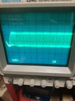
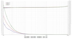
There is a lot of high frequency around us and i thought a shielding might be a good thing to prevent the high frequency creeping into the amplifier and disturbing the feedback loop with the result of a bad sound. So i bought some shielded 2x0,75mm² cable, connected the 2x0,75mm² as usual and the shielding to the amplifiers ground (a: directly; b:via resistor). It showed up, that in both cases the sound gets worser than before. A look at the oscilloscopes screen showed the reason: the shielding worked as an antenna and did the opposite of what it was intended to do.

Looking around in several forum showed only subjectivists views, none of them showed any technical description...therefore some questions:
- is shielding necessary / useful? If yes - how should it be done? If no - why not?
- is a ferrit clipped on the cable helpful? (as it is dampening common mode signals that reached the cable)
- does shielding help, even when it is nowhere connected? (as it is good practice in KNX home automation cabling)
- what is the optimal diameter for the cable? (with respect to the skin-effect)
- is a twisted pair better than a parallel cable? (as signals that reach the cable are inducted in opposite direction and therefore cancel)
- is the star quad configuration better than twisted pair? (as it promises a better immunity to magnetic fields)
- is coaxial-cable the solution? ( as it is shielded and, referring to cable-theory, all the inductive and capacitive fields from the current that is running through the cable happen inside, and the shielding works as such when connected to ground)
- what is the best way to test and find out?

At what voltage and frequency defining the OPTs leakage inductance

At what voltage and frequency defining the OPT's leakage inductance ?

Measuring Leakage Inductance Lsp is usually defined as shorting the secondary and measuring the inductance on the primary winding.
However, Lsp is strongly dependent on applied voltage and frequency as shown in the attachement.
When a transformers primary inductance Lp is specified at 230V@50Hz, it will simply not be possible to use this same voltage and frequency with a shorted secondary winding because it will blow the OPT into pieces.
Nevertheless, to calculate the quality factor, one has to know the corresponding Lsp because Qf = Lp/Lsp.

In the attachment below, several Lsp measurements are shown measured with a VNA with three different voltages, resp 1Vpp, 2Vpp and 4Vpp, resulting at 50Hz in resp 31.9mH, 22,5mH and 15.2mH.
So, Lsp is inversely proportional to the applied voltage, almost with the square root.
Going upwards in frequency all curves are coming together independent of applied voltage, resp 1.55mH@500Hz, 1.15mH@5Khz and 1.15mH@50Khz.
Interpolating this from 4Vpp to 230Vrms would result in 1.19mH at 230V, but how far off can this be ?

Hans

Attachments

  • Lsp.jpg
    Lsp.jpg
    232.7 KB · Views: 74

Give-Away (or Raffle or Sweepstakes): Vera-Fi Audio Vanguard Scout Loudspeakers (MSRP $299 the Pair)

Jack Baruth is best known as an automotive journalist. But he is a music lover and musician and audiophile and guitar collector. Jack's blog is called Avoidable Contact Forever. There is content that is behind a paywall, but there is a lot of Free content as well.

One item that is not behind a paywall is the above-referenced random giveaway of a pair of Vera-Fi Audio Vanguard Scout Loudspeakers. You enter by sending an email. The entry period closes Tuesday, August 6.

Win These Vera-Fi Speakers

Best of luck!

john
  • Like
Reactions: Roppu and adason

Help with Alembic F-1X/Clarostat Pot

I'm cleaning up a friend's preamp and need to replace a pot. It's a Clarostat, the back is stamped:
Alembic
475-001
20 9818
Mexico

I'm replacing because it tested linear from 0-380kOhms (1-8 on dial) then dropped sharply toward 0 (from 8-10). Based on that line's trajectory, I'm guessing it's a 500k pot, but if anyone could confirm that would really set me at ease for replacing. Also, by any chance does anyone have a wiring diagram so I don't have to decode resistor bands to test everything? Thanks so much!

Suggestions for 95 dB tweeter?

Hi guys
Im making a speaker for some outdoor concerts, and Im struggling a bit. I need a tweeter. I find it hard to find something in the realm of 95 dB sensitivity, and was wondering if you had any suggestions. It would be fine, if it was some waveguide or something that did the trick. As long as I land on something, where I don’t have to lower the sensitivity on my woofer. (As it is an outdoor build on batteries. I want it to play as loud as possible)


Thanks!

The frequency response of the FaitalPro 10” that I have laying around looks like this.
IMG_5793.png

Cizek Model 1

I picked up a pair of Cizek Model 1s this weekend for $5 (on a whim and knowing nothing about them but they looked cool). The cabinets need some refinishing but are solid, the grilles and foam on the front baffle is shot, the tweeters work as do the woofers but they need refoaming.

Are these something I should put the money into or should I just gut them and play with them DIY style?
  • Like
Reactions: head_unit

Plate chokes - choosing and using

I'm a big fan of plate chokes so starting a thread to compare experiences and see who else out there is a fan. As for what's available, we have these for starters.

Hammond 126C - 15mA - 106H - 3.7K
Hammond 126B - 30mA - 44H - 178R
Hammond 157G - 40mA - 30H - 595R - used in Hagerman Tuba

Lundahl LL1667 - 15mA - 270H - 2.4K - (other models available)
Lundahl LL1668 - 25mA - 100H - 680R - (other models available)

Plus many others from smaller transformer winders. For instance, I use NP Acoustics amorphous chokes from Vietnam which I like a lot.

What are your experiences of plate chokes and hot tips for good ones?

More fun & games (For my next trick)

I'm spoiled. All the sound systems in my apartment are perfect. I am particularly proud of my under-bed sub.
Our garden system sounds good too (an entirely different conversation).

The fun part is that the garden cupboard sits on a pallet.

A UK pallet measures 1200 x 1000 x 130mm - a whopping 120 litres!

Of course I'm thinking SUBWOOFER!!
The 130mm height provides serious challenges but wouldn't it be an engineering coup to design something half decent?
  • Like
Reactions: stv

One I2S source and Two DACs, what is the best solution to switch between them

My new setup will be a Windows 11 PC with a Pink Faun I2S Bridge https://www.pinkfaun.com/shop/bridg...tml#/521-additional_clock_for_i2s_bridge-tcxo

I collected everything to build an @iancanada DAC like this with the power supplies https://iancanada.ca/products/flagship-full-function-sync-clock-mode-ess-dac

The re-clocked output goes directly to the DAC

I'd also like to build another DAC and switch between the two. Or, build the Iancanada as a streamer and then just have both DAC's user HDMI I2S receivers and switch between those. What's the best way to do this?

My custom "portable" HiFi loudspeaker (lots of pics!)

Some time ago, I wanted to build some reasonably high-powered "portable" HiFi speakers that I could lug around outside (when working around the yard) or bring to parties, etc.

My design goals were:

1) It should [obviously] sound better than your average store-purchased BPC (black plastic cr4p) deal found at Circuit City
2) It should have plenty of power to clearly play for extended periods in small outdoor settings
3) Capable of being powered from my 20v DeWalt batteries - so I can cut the cord when needed.
4) No frills, but it should accept basic balanced input so I can maintain clean sound when driven my my next project (portable HiFi mixer/pre-amp w/ bluetooth).

Anyway... the overall design and specs are as follows:

Each Speaker
-> 10" Dual voice coil subwoofer. 4 ohm per coil, 200 watt per coil. This driver covers 220hz on down.
-> Dual 3.24 inch midrange covers 220hz to 3400hz. These drivers were actually reclaimed from some old Polk Audio sat speakers that had rotted surrounds.
-> Single dayton audio 1" soft dome tweeter to handle 3400 on up.

The 10" was originally powered by a single TPA3116D2 (mono) chip amp - but that board just did not have the beans to really keep the sub going at high levels and would shut down at high volume. I eventually replaced the TPA3116 mono board with a TPA3255 (stereo) amp board. Since the entire speaker is designed to run with 16-24 volt range, I had to get the voltage up. So the TPA3255 amp is now powered with a cheap 500 watt DC-DC boost converter (bosting to 36 volts). This now gives me 150 per voice coil and is PLENTY. Easily stands up to most commercially purchased subwoofers found today (the extra large cabinet helps on the low end).

The two 3.25 inch midrange drivers are powered from ONE channel of a TPA3116 (stereo) amp, and the dayton silk dome tweeter is powered by the other channel.

I did build a time-delay circuit w/ a 555 timer (with fast reset) and optocoupler that ensures both the 3116 and 3255 amp boards are forced into mute mode until power levels are over 16V and 3 seconds have passed. This ensures absolutely NO power-on pop happens. I was especially concerned that the tweeter - which is connected DIRECTLY to the amp output could experience damage by any power-on pop that the 3116 is bad for.

All three channels of amplification (well, the sub is actually TWO channels).. are passed through a 12db/octave LR crossover design that was clobbered together from Elliot Sound products website (thanks!). I also built a balanced receiver (also from Elliots site) that can work in single ended when desired.

The back "amp plate" faceplate is 5mm MDF laminated in 3M vinyl (brushed titanium). The faceplates were built by cutting and engraving on the laminated boards. Result is a pretty professional looking plate. If I had to do it again, I would likely fnd a way to print the lettering on the vinyl with a transfer or dye sub printer of some sort.

The cabinets are 5/8" MDF (remember, these have to be somewhat portable!). The MTM upper speaker set are isolated in a sealed inner enclosure. The final finish is a spray-on truck bed liner that I buy by-the-gallon (water based).

The driver and mid range units all had ugly (basically no) outer trim/beauty ring. Thus.. I cut some custom beauty rings for each (again, on the laser cutter) and painted them satin black.

Finally... here come the pics:
  • Like
Reactions: IamJF

ES9038Q2M Transformer Output Questions

OK, apologies if this has been detailed out elsewhere, but cannot determine proper direction.

I have been playing around with a cheap ES9038Q2M based DAC board that has dual opamp outputs (OPA1612 - possibly fake?). Stock it sounds very good (once you are able to correct the polarity out issue - no longer being sold on ebay as they have been recalled).

Anyway, I would prefer Balanced out to my balanced amps.

I have a few transformers...

JT-11-EMCF (600:600)
Sescom MI-52 (400/400:50k)
Sescom MI-8 (150/600:600)
Sescom MI-14 (150/600: 150/600 & 150/600)

Also have DRV-135 PCB that will also convert Unbal to Bal. Plan is to just pull the OPAMPs and take the ES9038 +/- out right off the OPAMP socket to transformer primary or input to DRV-135 for now.

Questions:
#1 - Which transformer would work best for Bal out? I have read that the ES9038 is a current out DAC, so 1:1 may not be ideal? See attached
#2 - Transformer or DRV-135 conversion - are either of these able to output Bal and Unbal Simultaneously?

Appreciate the advice!

Attachments

  • common_circuit.JPG
    common_circuit.JPG
    132.1 KB · Views: 150
  • Capture.JPG
    Capture.JPG
    49.9 KB · Views: 136

Hello from Linz, Austria!

Hello Guys!

I watched a few videos on youtube in german from "Franks Lautsprecherwerkstatt" and got a bit inspired regarding electronic audio design and i have some motivation to get my hands dirty.
I have an idea which is probably too big for me alone: to create a Pre-Amp with a modular bus system. This is something that i never saw on the market.
The reason for this idea is, that everone has different needs for a Pre-Amp at home. And also a different budget or DIY skills.
Having a nice Pre-Amp with a display and universal knobs, which is very flexible regarding it's functions would be great.
A motherboard with a bus system with PCB connectors similar to an ISA/PCI bus in a PC that has pins for a lot of analog and digital audio signals and communication signals with the board might be a good idea.
Example: i have some analog sources and some digital sources. and i have a phono player. Not everyone has a phono player. That means a phono-pre plug-in board with connectors on the back would be a cool thing to have as an option. maybe someone has analog signals in symmetrical version. that means he needs an input card that has symmetrical inputs.
someone wants to have an analog fm radio ==> another card to plug in.
maybe some cards in basic quality but with very simple and cheap parts (cheap phono stage). or a more high-end approach with a more complex design and more expensive parts (high end phono input).
a simple fm radio card, and maybe one with digital stuff as well, like DAB or DAB+. a card that has digital inputs. cards for output. something very simple with a simple and cheap opamp. or something discrete and maybe with symmetrical outputs. maybe a subwoofer output card with analog knobs on the back to adjust the filter frequency etc.
a simple cheap power supply or a much better power supply that has a better channel separation and different paths for digital supply, analog supply, etc.
It this something that would resonate with your needs? please tell me, if such a modular system is missing in your home. also as a base for upgrades, start cheap, go big later....
greetings from Linz, Austria,
Funkmaster WhyLee.

Anyone wound their own flyback or LLC resonant converter transformers?

Hi.

I've been researching building flyback and LLC resonant converters for a while now. I know you can buy flyback converters cheaper than you can buy all the components but it's a very interesting area.

A major stumbling block seems to be that the transformers required must be custom built.

Chinese manufacturers I've approached aren't interested in only a couple of transformers.

I've seen a youTube video where someone wound their own small flyback transformer with a manually operated winder with a counter but it's hard to get professional quality (the winder was actually meant for tube amp output transformers). The different diameters of magnet and triple insulated wire can be expensive and difficult to get too.

Anyone had any experience with obtaining or winding customer SMPS transformers?

Thanks.

ISODA Speaker HB-55 HB55 Single Wire Cable - what other Option?

The cable from the attached images are already since a long time no longer available from currently manufacturing.
Sound quality very good in all respects.
What alternatives should one shortlist?

And a second question:
In what way is it best to make the connection to the plug
From my view image II seems to be a good approach but image VII not.

Thank you very much for advices.

P.S.: Here a description concerning ISODA cable (Audiophile n°36):
http://6bm8.lab.free.fr/Documentations/Revues/Audiophile/1977-1988/36/PARLE/PARLE.html

Attachments

  • ISODA HB-55-I.jpg
    ISODA HB-55-I.jpg
    117.8 KB · Views: 343
  • ISODA HB-55-II.jpg
    ISODA HB-55-II.jpg
    155.9 KB · Views: 342
  • ISODA HB-55-III.jpg
    ISODA HB-55-III.jpg
    133.7 KB · Views: 337
  • ISODA HB-55-IV.jpg
    ISODA HB-55-IV.jpg
    119.8 KB · Views: 332
  • ISODA HB-55-V.jpg
    ISODA HB-55-V.jpg
    109.7 KB · Views: 346
  • ISODA HB-55-VI.jpg
    ISODA HB-55-VI.jpg
    415.3 KB · Views: 316
  • ISODA HB-55-VII.jpg
    ISODA HB-55-VII.jpg
    315.6 KB · Views: 308
  • ISODA HB-55-VIII.jpg
    ISODA HB-55-VIII.jpg
    213.6 KB · Views: 364
  • ISODA HB-55 datasheet cover.jpg
    ISODA HB-55 datasheet cover.jpg
    339.9 KB · Views: 213

Please suggest the Crossover and Cabinet details for the combination of drivers Peerless HDS -P830990 & Vifa BC25TG15-08 for bookshelf

Dear All,

Can you share the cabin size and custom crossover details for the bookshelf with the following combination of tweeter (BC25TG15-08) and woofer (HDS -P830990 ) ?..

Attached datasheet of both drivers.

Please help me to find the best output.

Attachments

Hello from Barendrecht the Netherlands

My name is John and I used to cut records during 2000-2003 in Rotterdam,I was trained for this In Miami by Aldo Busio and George Garcia.
Nowdays I'm a owner of self build JBL monitors and speakers and always in search for JBL 2225 speakers.
Hello to all members!

9-9-22 003.jpg

Attachments

  • johannes richter2.jpg
    johannes richter2.jpg
    156.5 KB · Views: 44
  • johannes richter3.jpg
    johannes richter3.jpg
    146.6 KB · Views: 44
  • soundstream 2003.jpg
    soundstream 2003.jpg
    186.8 KB · Views: 43
  • soundstream-2 2003.jpg
    soundstream-2 2003.jpg
    165.2 KB · Views: 48
  • apr18_01.jpg
    apr18_01.jpg
    249.2 KB · Views: 42
  • Apr18_06.JPG
    Apr18_06.JPG
    278 KB · Views: 42
  • Apr18_12.JPG
    Apr18_12.JPG
    277.8 KB · Views: 43
  • Apr18_19.JPG
    Apr18_19.JPG
    300.7 KB · Views: 49

HV Voltage ARC

My amp uses 2500 plate voltage. At start up I occasionally hear an arc, but cannot see it. Never blows a fuse. Once running no arcs. I have better than 1/4" in-between HV conductors except at each can capacitors that the aluminum case is not connected to anything and it has a plastic sleave with 1/8 clearance from ground. Caps have an 1/8" clearance from case with the 600 volt insulated wire on the negative leads only and each cap sees 325 volts. The can caps case is at least 1/8 inch from the grounded case. It uses a voltage doubler and eight 220uF 400 volt capacitors in series. Each doubler leg uses 3KV of diodes. The HV has a 1000pF 5KV capacitor to ground. PSDII shows less than 50 volts overshoot at start up. No chokes in HV circuit. I do not get it

The importance of Kms(X) and BL(x) for mid-ranges

edit: new discussion about issues related to drivers other than just only midranges;
https://www.diyaudio.com/community/...l-x-for-mid-ranges.376164/page-7#post-7703832

Hopefully this is the right subforum for this.

I have a question about the following,

So for loudspeakers there are basically three dominant factors creating distortion/non linear behavior.

  • The non-linearity of the compliance (1 / stiffness), Cms(x)
  • The non-linearity of the BL vs displacement curve, BL(x)
  • The non-linearity of the inductance. Le(x)

There are some other factors, like cone break-up, compression of air etc etc, but for now I am not going to consider those.

So the BL(x) and Cms are both dominant for the lower frequencies, around the Fs up to roughly 2 x Fs.
From that point on the inductance Le(x) is starting to be the more dominant factor.

So let's assume we have a mid-woofer with a Fs around 50Hz.
We are gonna cross this driver (actively) around 100-120Hz (2nd order highpass)

At this point, as far as I understand, it's not really important anymore how (non)linear the Cms and BL(x) is, since the Le(x) is dominant here?

As long as we keep the cone excursion to a minimum, which is most cases is fine since most speakers will run into there max power at this point with a cone excursion of just 1-3mm or so.
  • Thank You
Reactions: camplo

Hi from Australia

Hi all,
I came across this forum as I am trying to reproduce an amp that was found in an old arcade machine. Restoration of some of these old machines becomes difficult as parts like this just disappear into history. The work so far in getting the schematic together has been completed by others but it appears I am the first to attempt to actually build it. I thought it may be useful to have access to a resource like this forum in the attempt.
All of my electronics experience comes from arcade pcb repair so audio may be a bit of a mystery to me.

New to the group and in desperate need of Help

My name is Austin im new to the group and need some guidance im new to all of this so be easy on me, i had the bright idea of building a portable bluetooth speaker and just started ordering stuff on impulse with no plan or anything so i currently have 2 Grs 3” fullrange drivers 4ohm 20watts max and 2 6.5” polly cone midbass woofers from parts exspress there 40 watts rms i havent got an amp yet but question is can i use all of these speakers and make them sound decent if so what do i need to make thst happen cross over, filter or what ever id like to be able to just buy somthing pre assembled and throw it in cross overs just thinking about them gives me a headache or do I need to start from scratch and if so a good cheap combo of speakers that would make a decent bluetooth speaker with some decent bass thanks in advance.

Mark Levinson ML-9 recapping (1985)

Hello to all.

I've decided to recap my old ML-9 amplifier, which, I think, deserve it 😉

At the moment, I'm looking for 1) finding as much and well the same references than the original ones (which is a fancy yet uneasy job 😉 2) finding the right way (procedure) to replace the capacitors on the amplifier board (which seems uneasy too, considering the way it is built, as I'll explain).

I’m not a professional but I’ve got plenty of time, I already recapped several small amplifiers (like some Cyrus 1 and 2 and other electronic devices), and I’m equipped with all the necessary tools. But if it appears that it is impossible for someone like me to achieve the task, I’ll try to find a qualified professional to have the job done…

Then.

1. finding the same references than the original ones. Easy for certain items. Difficult or impossible for some others. Possible with a few references if you buy 10 or 300 of them (depending on the item). For instance, I’ve chosen to replace the original Sprague 36DX 36000uF/100V by new United Chemi E36D101HPN363UEM9N bought from M…r (same voltage/capacity/size) which, I believe, are widely used by Madrigal to recap old ML amplifiers. Those capacitors are not on the signal path and should do the job. Selecting Cornell or Vishay (Sprague) of the same type would have demanded that I take at least 9 of them, which is rather expensive.

I couldn’t find the 10/100V same polycarbonate caps (and as film caps I suspect they are not too bad even after 35 years of use), but I bought East German RFT NOS 10/100 polycarbonate caps, in case (they seem OK, cap 15uF and Vloss 2,5% - acceptable?). I could find NOS Sprague 39D series 520/100V caps, and I’ll check the Vloss and ESR when I got them. Hoping they are OK or that I could reform them if necessary. I could find NOS 10000/10 Frako (same question than previous). I could find new TE1105 250/6V at M…r.

Then I’m wondering what to do with the 672D Sprague 680/6.3V/105° which are used in the DCO suppressor circuit. If I’m not mistaking, they should be on the signal path. Impossible to buy less than 291 units… at 3,5/unit, I won’t do it. So I’m looking to find a substitute, but which? I found this: UPM0J681MPD6TD (UCC). Rippled current is at 825 mA which could match the particular position of these caps. But I’m fairly ignorant about this point (and many others…). A helpful advice will be happily considered 😉

2. Assuming that I found all capacitors needed. The physical operation of replacing them has yet to be done. (!) Rather simple when access to the whole circuit board is open and clear. The power regulation board and the DCO board are in this case. BUT not the amplifier board, which is almost stuck to the large radiator, the transistors being on the outside of the radiator, their pins soldered on the inside of the board, where all the components are. A kind of sandwich, where to take out the board in order to have a full access to the soldering points of the components (the board seems to be a double sided board with different tracks on one side and on the other), you have to unsolder the 10 power transistors and un screw them. Which is a delicate job to do, especially when you see that some transistors pins are VERY close to some components. The pictures show this, I hope.

Then.
What to do? For the first part, advice is required for a suitable match for the two 672D Sprague 680/6.3V/105° in their particular location (DCO circuit).
For the second one, I haven’t taken everything apart yet, hesitating to do that at this point. Do I have to unsolder all transistors so I can have full access to both sides of the circuit board? Would it be necessary, would it be possible (even if not a proper job, I admit) to cut the leads of the existing caps and solder the new ones on them? (please don’t throw too many stones at me 😉. Or just unsoldering the defective (read old) parts and solder the new ones on place with enough welding to go through the hole (but not too much)?
I’m trying to understand how this was done by the manufacturer by observing carefully the board and it seems to me that at least the two 520uF Sprague Caps couldn’t be soldered before soldering the transistors… if this had been done, how could they have soldered the last transistor with so little space available? (but this is Mark Levinson and their techs are probably above the average humans about soldering).

Thanks for reading 😉 I'll be more than happy to read all of your comments and considerations!

please excuse my poor English and the quality of the pdf docs.

Attachments

  • ml-9 amplifier board and radiator.jpg
    ml-9 amplifier board and radiator.jpg
    615.3 KB · Views: 1,421
  • ml-9 amplifier board reduced.jpg
    ml-9 amplifier board reduced.jpg
    792.1 KB · Views: 1,927
  • ml-9 part DCO board.jpg
    ml-9 part DCO board.jpg
    807.6 KB · Views: 1,292
  • ml-9 regulation board.jpg
    ml-9 regulation board.jpg
    615.2 KB · Views: 1,345
  • ml-9 transistors_radiator.jpg
    ml-9 transistors_radiator.jpg
    808.8 KB · Views: 1,670
  • ML-9_schema-DCO Protector.jpg
    ML-9_schema-DCO Protector.jpg
    698 KB · Views: 1,304
  • ML-9_schema_amplifier board.pdf
    ML-9_schema_amplifier board.pdf
    136.9 KB · Views: 558

2SK240-Y

I was browsing an old electronic parts shop in my city when I accidentally spotted some 2sk240s with a grade I had never seen before. I was curious, so I picked up a few. I checked the Toshiba datasheet, but I couldn't find this grade listed. Do they really exist?

Thanks

Attachments

  • Screenshot_20230831-110341~2.png
    Screenshot_20230831-110341~2.png
    331.7 KB · Views: 218

Foster 100K03 PA speaker

Hi guys,

I'm only posting this as I thought these mildly interesting, hence I bought them.

These apparently came out of a church and I presume there were more as they have variable autotransformers to balance output and transformers for 100v line use. The hanging hooks suggest one was mounted horizontally and the other vertically.

The drivers appear like new. I can't tell whether the surrounds are stiffer than original, however, and have not yet measured Fs.

I haven't yet fired them up as the wiring has been played with.

Ignore my file name I know they hardly qualify as line arrays...

I'm not sure what to do with them, but one of the drivers may go to a table FM radio I'm making...not so thrilling I know! ...but after I've played with them with the autotransformer removed and wired in series/parallel to test them as is in the box.

Cheers

Stuey

Attachments

  • Foster Line Arrays.jpg
    Foster Line Arrays.jpg
    24.5 KB · Views: 107
  • Foster 100K03.jpg
    Foster 100K03.jpg
    23.8 KB · Views: 106

For Sale [ADL] Manzanita OB Air Core inductors

As above.
I have a set of air core inductors for the Manzanita OB outlined in the 'Fast, fun, Inexpensive OB project' thread.
Due to downsizing I no longer have the space I need for these speakers - so I shall move them on and pick a smaller project.

View the above thread, circa post 800-821 to see their origin. One of the larger inductors has extra turns 😉

A$150 for the set of 4. Would prefer local pickup as these guys are weighty, 2.3kg for the large, 0.6kg for the small, but will post at buyers expense within Australia if requested.

Attachments

  • IMG20240731103008[1].jpg
    IMG20240731103008[1].jpg
    411.5 KB · Views: 49
  • IMG20240731103017[1].jpg
    IMG20240731103017[1].jpg
    319.7 KB · Views: 48
  • IMG20240731103028[1].jpg
    IMG20240731103028[1].jpg
    374.9 KB · Views: 53
  • IMG20240731103136[1].jpg
    IMG20240731103136[1].jpg
    332.2 KB · Views: 54
  • IMG20240731103254[1].jpg
    IMG20240731103254[1].jpg
    323.2 KB · Views: 49

β22 Stereo Amplifier / Linestage Preamp/ HeadPhone Amp

A completed set of Beta22 amplifier and Sigma22 PSU that can be configured as a linestage preamp, a headphone amp and even a low power amp to drive sensitive speakers.
This amp is built as a 2 amps for stereo channels + 1 amp as active ground.

More information here:
https://www.amb.org/audio/beta22/

It is built on a backplane board :
https://www.amb.org/audio/epsilon22/
Hence the amp looks neat and sleek, will less wirings running all over the place.

Powering the amp is the Sigma22 regulated PSU:
https://www.amb.org/audio/sigma22/

Transistors, including the matched quad of 2SK170/2SJ74 per channel were bought from AMB LAB during those years when they were available at their online shop. Hence you can be assured that they are genuine. So there are a total of 3 matched quads of these precious FET in this amp.

This projected was built and tested, played without a chassis some time ago. I had the ambition of building a customised superb heavy steel chassis which did not materialise due to many distractions. Despite that it was commissioned to work, i do suggest that you read the information at AMB LAB, power up, test and monitor and trim the dc offset carefully.

A lot of effort and time has gone into putting this together using premium parts from legit /authorised sources.

I am asking for 420 USD (Shipping is covered).

150w or 200w PSU for Dayton KABD-430

Hi,

I want to assemble a small active 3 way speaker design and I will be using the Dayton Audio KABD-430 amp. which has an integrated ADAU1701 DSP.

https://www.parts-express.com/Dayton-Audio-KABD-430-4-x-30W-Bluetooth-Amp-Board-with-DSP-325-430

The idea is 2x 30W (tweeter and mids) + 1x 60W (woofer). I know it's not much, but these will be used in a small room with 4+ subwoofers.

The thing is that I need a power supply for the 120W of total power. Is it OK If I go with a 150W SMPS? Or it's recommended to go with 200W?
I am thinking in the LRS line from Meanwell.

Amp + DSP will be in a separate compartment from the SMPS.

Looking forward to your replies.

Arcade Amp power supply question

The background to this is that I am attempting to reproduce the amp in the schematic for an arcade machine restoration. These things are now quite rate and difficult to find.
You may note that in the power supply schematic there is a note that this schematic is for an amp running of a VAC toroid transformer but it was also built to run of 12VDC. Of course I need the 12VDC type. Given that I am guessing the coil referred to as replacing the bridge rectifier is an inductor or choke. My question is how do I work out the best value for this component. Power is comming in from a pretty basic switched PSU.

Attachments

  • CPB-001A.pdf
    CPB-001A.pdf
    95.6 KB · Views: 73
  • Screenshot_20240731_113703_Samsung Internet.jpg
    Screenshot_20240731_113703_Samsung Internet.jpg
    156.6 KB · Views: 66

Fractional Octave Filtering

One of the options in REW is for fractional octave filtering of the speaker response. Since the source code for REW is not available my question is does anyone know the formula or a link to the formula for fractional octave filtering of response data. I am trying to program it into code I am writing and cannot find an algorithm. For example is what is done is to apply a linear Gaussian filter using the log of the frequency data as an input? I can't think of any other way of defining a filter as a fraction of an octave. Also what is the most efficient way of implementing the Gaussian filter? I hope some of you have knowledge of these considerations.

Simple dual relay soft start

Hi guys,
I would like to ask your opinion about this dual relay soft start. I believe both schematic are based on Elektor.
I am doing a modified lay-out with ideas based on both schematic, but I have added parallel diodes on the relay coils. Will this be ok?

Thanks!

Attachments

  • power.jpg
    power.jpg
    64.2 KB · Views: 919
  • delay.jpg
    delay.jpg
    39.1 KB · Views: 853
  • dual_relay_soft_start.JPG
    dual_relay_soft_start.JPG
    317.2 KB · Views: 992
  • Like
Reactions: Alexium

Jeff Bagby's Continuum IIs - plans? Or similar designs currently available?

They used to be available @ Meniscus Audio, but they have gone out of business and the plans are nowhere to be found. I'm very interested in building them, I have a friend who has access to a CNC machine and I could probably build them in a short time. If they are no longer available, are there any comparable sealed designs (maybe with a bit more bass extension)?

Are you a Dead Head?

Come on, admit it... a bunch of the people at BA23 looked like a bunch of old Dead Heads with a hair cut.

Then you got the long haired NorCal "hippies", who let's face it, look like they ought to be sitting at night playing tapes of Dead Concerts over a half track Revox while a phalanx of lava lamps lights up the coast all the way to Hawai'i. (1) (2) (3)

I wonder... should NP sell the four-pack-quatro-pipe-os. You know, four cylindrical bass tubes, one tuned for each string of Phil Lesh's bass... the way he had his amps wired for the Wall Of Sound...

So, are you a Dead Head?

I was surprised not to have heard any of their stuff being demo'd over the systems over at BA23. Of course, it might have made those demos a bit... longer.

Me, but of course. I got the Dead Head Channel on XM and I got a lot of live Dead Head CDs that I put into my cell phone ( at Redbook) so I can play it over Android Auto.

Heck my drive from SoCal to Petaluma was mostly Dead and Bakerfield country ( Buck Owens, Merle Haggard, etc...)

Good stuff to listen to.... best stuff to drive to.

Or as someone in these forums might call them.... Die Dëad Hæèd. He listens to them at 11 when the wife is out shopping.

Note, sometimes, I love Hawai'ian Country music too.

(1) In my college youth, generally my group of male friends fell along two sides... a bunch of hippie looking guys and another bunch of yuppies. The hippie group treated their bodies like Holy Temples... the yuppies... well... we had a great time. Oddly, a yuppie could be coming down fast but still be miles above the hippie... but the cops never bothered us!

(2) I need to figure out how to make a lava lamp work with an LED lamp. Hmmm, come to think about it... maybe the SissySIT might be hot enough to run a lava lamp?

(3) Hey moderators, don't get upset now... all of this is said with a lot of humor. Hmm... do Blue lava lamps sound better than Green lava lamps?

For Sale Tentel Tentelometer Tape Tension meter $250 + SH

The Tentelometer is the user proven tape tension gage to diagnosing problems in tape transport of tape deck, reel to reel, vcr or other tape machine.

The Tentolometer measures in-line tape tension directly by sliding the probes over the tape.
This device I have for a long time and I have not use it for a long time since I don't service tape machine over 10 years ago.
The re-print user instruction with calibration instruction included.
Selling as is since I don't have anyway to calibrate the accuracy of the unit.
Meter needle still move freely with light press on the probes.

Includes:​

Tentelometer tape tension gage
instruction manual
Asking $250 OBO + SH + PP fees (Friend Family OK)

Attachments

  • IMG_9294.jpg
    IMG_9294.jpg
    473.9 KB · Views: 84
  • IMG_9286.jpg
    IMG_9286.jpg
    456.4 KB · Views: 71
  • IMG_9287.jpg
    IMG_9287.jpg
    742.8 KB · Views: 53
  • IMG_9288.jpg
    IMG_9288.jpg
    618.5 KB · Views: 48
  • IMG_9289.jpg
    IMG_9289.jpg
    440.4 KB · Views: 53
  • IMG_9290.jpg
    IMG_9290.jpg
    796.2 KB · Views: 50
  • IMG_9291.jpg
    IMG_9291.jpg
    693.4 KB · Views: 52
  • IMG_9292.jpg
    IMG_9292.jpg
    664.4 KB · Views: 53

Troubleshooting SMPS noise

Hello,
New to site and looking for your feedback. I'm an electronic enthusiast by hobby. I had some training in the Navy but now I have a renewed interest. In my 70's but still playing hard, and I'm mostly interested in troubleshooting the sm power supply for my Alto TS115a 800W powered speaker. My interest is in music and people enjoying music, DJ type hobby and playing drums. So this year I built a nice e-work bench and got serious.

I left my speakers on one night but next day I was hearing what sounded like a lower frequency machine gun sound from one of the speakers. I replaced the speakers and controls from the other speaker and everything seems to point to the switch mode power supply. Troubleshooting began but I broke it (shorted a couple of components) before I had a chance to troubleshoot the "machine gun sound". With the short now fixed I'm hoping to get some suggestions.

I joined this forum to reach out to some experienced audio techs that have come across similar issues. Thanks ahead of time.

What: Older Alto self powered PA speaker. 365W + 65W switching power supply.
Symptoms: Intermittent machine gun sound, slow repetition advancing to fast repetition with no signal input and volume set at zero.
Here is a link to the video and sound.

https://drive.google.com/file/d/12U6TH6vTTvJJH4DiMPjUQKN4GxpRU7ra/view?usp=drive_link

Never sent a link to a file before hope you all can open it.

For Sale Project Kits for Sale - Pearl 3, Pass Front End, Mofo

I have some projects for sale I decided not to finish and post to pay for some house work and supplies after Hurricane Beryl.

Pass Pearl 3 Project - SOLD
  • Pair of Pearl 3 boards, fully stuffed and tested (does not have the DRV135 for balanced and no opamps)
  • VRDN Power supply set up for a wall wart
  • AC to AC 16 VAC Triad Wall wart to get 18-19 VDC
  • with no transformer, you can put the PSU and the P3 boards into the same chassis
  • Plastic input 2.1x5.5 barrel
  • Asking $125 for it all plus ship

Pass Front End Kit - SOLD
  • Pair of stuffed Front End boards with Nichicon UES output caps and WIMA input Caps
  • LM337/317 regulator Power Supply
  • Antek AS-0518
  • All 3 pieces have been used and pulled from previous builds
  • Asking $60 for it all plus ship

Mofo Kit - SOLD
  • 4 Total Mofo Boards in White stuffed (except for the Mosfets)
  • 2 IRFP250 Mosfets
  • 2 Dell 19V Power supplies
  • 2 DC input barrels and connectors (2.1 x 5.5) to replace the Dell ends
  • Asking $80 for it all plus ship

I will upload pictures tonight. Ships out from Houston, TX.
  • Like
Reactions: 100ohms

Frozen Onkyo TX-8220

Hi!

I have a problem with my Onkyo receiver. After connecting the plug, the power automatically wakes up from stand-by mode. The main transformer is turned on and even the speaker output relays turn on. The default input source is "BD/DVD". When I put an audio signal into this input and connect the speakers, it plays and that's where the good news ends. No buttons on the front panel work, not even the volume encoder.
Combining the reset buttons does not work, but once I somehow managed to reset the device (the appropriate message "Clear" appeared on the display). Unfortunately, this did not bring any result.
Sometimes when I press the power on button, the software version probably appears on the display.


All voltages from the stabilizers are present.
I am wondering about the high state on pin 69 (SYS_PROTECT) 3,3V of the main R5F364AKA microcontroller (IC7001). I scoured the Internet looking for some advice and most Onkyo receivers with similar symptoms had problems with EPROM, or at least that's what they suggested on the forums.
Previously, the receiver did not respond at all and I decided to short pin 9 (RESET) on the P7004 socket to ground and since then the equipment has been starting as I described above.

I could try to upload a new batch to the EPROM, but I couldn't find it anywhere.

This is where my skills end.
Thank you in advance for all your tips

20240730_153003.jpg
20240730_153046.jpg
20240730_150318.jpg
20240729_220709.jpg
.

Attachments

CT vs non CT

I am wondering if there is a difference between a transformer with two secondaries being wired in series, compared to transformer that is center tapped. Can you use the common wires that are tied together in the first example and all that the same as center tapped? I asked because the design of the power supply allows for either non center tapped or center tapped.

LM1875 XY board

First post to the forum...

I recently purchased a few of the LM1875 XY boards from Ali Express, but there was no schematic included to compare with the data sheets for the chips, and as a relative newbie to DIY Amplifiers and I am confused by a few items.

I was initially confused by J3, but after a few hrs of research online, I found some photos of a KBL04 bridge rectifier in its place. I was also confused by C1 and C4, as there were numerous holes supplied and it only called for a 1uf capacitor. I have since realized that the extra holes were to be able to choose different sized capacitors perhaps?

Anyway, after scouring some threads, it appears that there are some issues with the power supply being inadequate... So I was wondering if anyone has used these boards to build either a LM1875 or TD 2030/2050 "decent" sounding amplifier, if they wouldn't mind sharing their build ideas or links to threads that I can explore, or any other recommendations before I start soldering... I'm basically just looking to build a decent sounding power amp to power some YAMAHA S115V PA speakers that I had laying around....

Thanks in advance!

XY LM1875 board.png
LM1875.jpg

Building a large four-way, using premium, JBL drivers, building test cabs and would love some input

For the sake of this thread, I’m going to refer to this as a pair that I am building, but I will be actually building three so that one can be used as a center channel in my theater. These will of course, be used for theater, but will get tons of musical use.

This is going to be a fully active set up, with the exception of the horns, which will use charged couple passive crossover designed by JBL. For the upper end, I will be using a 045Be beryllium 1” horn tweeter/super tweeter and a 435Be 3” beryllium mid loaded in a H9800 horn.

IMG_1918.jpeg

IMG_1919.jpeg


IMG_1920.jpeg

IMG_1921.jpeg


For the safety of these drivers, I think it would just put me at ease if I were to drive them with this passive crossover
IMG_1922.jpeg


The crossover, the horns, and the midbass drivers were pulled from a trio of SK2-3300s.

That brings me to the midbass drivers which are going to be 251J. These are a fairly rare and special version of this series of driver, they weren’t used into many designs, they have the aquaplas and added mass over the originals. For the bottom end, I’m going to be using 15 inch woofers that were used in some of their nicer subwoofer designs, though they have been used in three-way designs with much success, they are 1500 sub drivers.
IMG_1916.jpeg

IMG_1917.jpeg


Dan

Output transformer Hi Frequency resonance; How high?

Hi everyone,

I recently wound a OPT for 6336 SET amp with 2.5K:8ohm impedance ratio and 10W max output power, pretty similar to 300B. Yesterday I did some testing on this OPT and everything was exactly as the design, except one thing; Hi F resonance (I mean the series resonance of Leakage Inductance and Shunt Capacitance), was at around 34KHz which is lower than my previous builds.

So here is my question; what negative effects can this cause? (bearing in mind that there is no negative feedback in this amp). I know that it can cause Hi F roll off and you can see F response at 20Khz rolled off at about -0.3dB, but is it that important? What is the other side effects that I'm not aware of?

I attached some images from my measurements:
Open Zp.jpg

F response low level.jpg

Closed Zp.jpg

Hi F THD.jpg

Whammy headphone amp

Hi guys!

Build the amp and have an issue. It works great with the Audeze sine 18Ohm but distorts and low frequencies with the 35ohm focal elegía. I tested with 18R and 35R load and confirmed the 35R load produces distortions at the lower frequencies. So I cheated and placed a 18R resistor on each output on parallel and the focal sounded great as well.
I have done a version with irf610/9610
And a Fairchild version with the FQP’s
Both have same issue.
For op amp I used the opa1611

Schematics is same as original, only went lower on negative feedback to 3K because it had too much gain

Any help appreciated

FS: NOS capacitors - PiO, Teflon, PETP, Hybrid PiO, Silver Mica.

I have in stock NOS-NIB capacitors - PiO, Teflon, PETP, Hybrid PiO, Silver Mica.
All capacitors are new, not soldered, before selling I can measure the capacitance and select a close pair (on request).

№ * Parts specification * Size (D x L), mm * Q-tity, pcs * Price, $/pc
PiO capacitors
1) К40У-9 0,47uF 10% 630V (20mm x 62mm), 25pcs 7$/pc
Teflon Capacitors
2) ФТ-2 0,1uF 10% 200V, (19mm X 50mm), 10pcs, 5$/pc
3) ФТ-3 0,47uF 10% 200V, (37mm X 73mm), 18pcs, 20$/pc
4) ФТ-3 0,22uF 10% 600V, (30mm X 73mm), 16pcs, 10$/pc
Teflon Capacitors
5) ОС К72П-6 0,015uF 10% 500V, (20mm X 34mm), 40pcs, 2,5$/pc
6) К72П-6 0,033uF 5% 200V, (18mm X 34mm), 30pcs, 2,5$/pc
PETP capacitors
7) ОС К73-16 22uF 5% 63V, (22mm X 48mm), 200pcs, 2$/pc
8) К73-16 10uF 5% 63V, (16mm X 48mm), 120pcs, 1,5$/pc
PETP capacitors
9) К73П-2 0,1uF 10% 630V, (14mm X 38mm), 100pcs, 2$/pc
10) К73П-2 0,1uF 10% 400V, (10mm X 36mm), 55pcs, 1,25$/pc
11) К73П-2 3300pF 10% 630V, (6mm X 22mm), 130pcs, 1$/pc
Hybrid PiO capacitors
12) К75-24 1uF 10% 630V, (22mm X 52mm), 15pcs, 5$/pc
13) К75-24 0,68uF 10% 630V, (18mm X 52mm), 12pcs, 4,5$/pc
14) К75-24 0,15uF 10% 630V, (11mm X 36mm), 30pcs, 3$/pc
Hybrid PiO Capacitors
15) К75-10 0,22uF 10% 750V, (28mm X 62mm), 10pcs, 5$/pc
16) ОС К75-10 0,68uF 5% 500V, (32mm X 65mm), 30pcs, 4$/pc
17) К75-10 0,15uF 10% 500V, (18mm X 62mm), 18pcs, 2$/pc
18) К75-10 1uF 10% 250V, (22mm X 52mm), 40pcs, 2$/pc
19) К75-10 0,68uF 10% 250V, (20mm X 52mm), 50pcs, 1,5$/pc
Silver Mica Capacitors
20) СГМ-4 0,01uF 5% 250V, (18mm X 22mm X 9mm), 30pcs, 1,25$/pc
21) КСО-2 1000pF 5-20% 250V, 100pcs, 0,5$/pc

"ОС" - means "especially persistent / stable"

--------------
PayPal payment

Best regards!
===========
Olexandr
Kharkiv, UKRAINE
skype: OAA-1974

Attachments

  • ft   001.jpg
    ft 001.jpg
    986.9 KB · Views: 524
  • k40y-9 001.jpg
    k40y-9 001.jpg
    760.3 KB · Views: 609
  • k73-16 00000.jpg
    k73-16 00000.jpg
    995.8 KB · Views: 559
  • k75-10 00000.jpg
    k75-10 00000.jpg
    863 KB · Views: 445
  • k75-24  001.jpg
    k75-24 001.jpg
    962 KB · Views: 634
  • k75-24 002.jpg
    k75-24 002.jpg
    1,004.5 KB · Views: 297
  • k75-10 003.jpg
    k75-10 003.jpg
    704.9 KB · Views: 391
  • сгм kcu 000.jpg
    сгм kcu 000.jpg
    1 MB · Views: 255
  • k75_24.jpg
    k75_24.jpg
    25.6 KB · Views: 243
  • FS NOS Cap - OAA7.pdf
    FS NOS Cap - OAA7.pdf
    207.2 KB · Views: 158

bipolar vs dipolar sub study

Few asked me about my dipole subs, and I used to have web page from the past, where I did comparison between subwoofer arranged as bipolar vs dipolar. It took me a while to find the link in wayback engine, since geocities took it down.

Here is the old web page link, directly it does not work, but enter it into wayback page:
http://edsaudiopages.blogspot.com/2012/10/the-search-for-musical-ecstasy.html
Here is the link to wayback:
https://web.archive.org/web/2015102...m/2012/10/the-search-for-musical-ecstasy.html
New page in the blog:
http://edsaudiopages.blogspot.com/2022/11/dipole-vs-bipole-subwoofer.html

I hope some will work. This is best sounding sub, I am using it for more than a decade. Enjoy!
  • Like
Reactions: Harry72 and pelanj

FS: 2П29Л / 2P29L + 2П29П / 2P29P + sockets - NOS NIB

Hi!

I have in stock NOS-NIB electron tubes 2П29Л / 2P29L and the same but in other box 2П29П / 2P29P and loctal sockets

1) 2П29Л / 2P29L Saratov factory "Reflector"
400 pcs in stock, the same date codes,
minimum order = 50 pcs (one box)
price = $2,5 for 1pc

2) 2П29П / 2P29P Saratov factory "Reflector"
150 pcs in stock, the same date codes,
price = $2 for pc

3) PL3-29 Loctal tube sockets
12 pcs in stock, NOS
price = $4 for pc

-------------------
PayPal payment

Best regards!
-------------------
Olexandr
Kharkiv, UKRAINE
skype: OAA-1974

Attachments

  • 29L 001 1024.jpg
    29L 001 1024.jpg
    228.4 KB · Views: 367
  • 29L 002 1024.jpg
    29L 002 1024.jpg
    432 KB · Views: 382
  • 2П29П 001 1024.jpg
    2П29П 001 1024.jpg
    278.8 KB · Views: 372
  • 2П29П 002 1024.jpg
    2П29П 002 1024.jpg
    238.4 KB · Views: 380
  • LOCTAL 001 1024.jpg
    LOCTAL 001 1024.jpg
    134 KB · Views: 376

RCF ND640 on HF94 horn

Hello guys,
I just received my New rcf Nd640 drivers and rcf HF94horns.
The horns are delivered with 2 throat. One for 1 inch and One for 1.4inch drivers.
But the nd640 (1.4inch throat) does not fit on the 1.4 inch throat adapter. It does fit on the 1 inch throat adapter.
Is it okay to use the 1 inch throat with the 1.4 inch driver? Or does it negatively affect the sound?

Low pass filter positioning on subwoofer

Hi, i recently build a back loaded box for my 18" woofer driver and I also used a low pass LC filter. I noticed that inserting the filter at the uotput of the aplifier does not work at all, no filtering action. Inserting it at the input, filtering so the input signal, gives the result that I was looking for. I was wondering why this happens, so I can understand better how filter for audio application works.

Thanks for responses.

PHILIPS GM2317

Picked up an interesting 50s Philips GM2317 sinewave generator.

Beautiful large dial, great for my deteriorating eyesight.

I haven’t turned it on just yet, first I need for find a socket that would fit to this antiquated power inlet, I could hardwire it, but would prefer to keep the originality of it. It does look like one of those used on old kettles.

There are a few aged capacitors in it. Is there a procedure on how one could power up old equipment safely? Should I hook it up to my variac and increase the voltage 20V at a time, then let it sit for an hour, then another 20V, until it reach its operation voltage?

Attachments

  • IMG_2799.jpeg
    IMG_2799.jpeg
    429 KB · Views: 73
  • IMG_2801.jpeg
    IMG_2801.jpeg
    384.2 KB · Views: 64
  • Like
Reactions: tubelectron

Changes to international shipping options

The following information affects international (non-USA) customers only.

Please see the official announcement for more details:

https://diyaudiostore.com/blogs/news/changes-to-international-shipping-options

Our warehouse partner has informed us at short notice that they will be unable to provide DHL eCommerce shipping options after this week. We will be accepting DHL eCommerce shipping in the checkout until 6AM on Friday 28th June 2024 EST.

We will continue to offer DHL Express, and will be adding USPS International services from next week. We will be reviewing all our options moving forward so that we can best continue to serve our valuable international customers.

If you are located internationally and would like to take advantage of our extremely low international shipping prices, now is the time 🙂

Tubes for sale

Hi,
Sale:
42 RCA - 3 pcs.

78 USA - 1 pcs.

80 Ken-Rad - 1 pcs.

89 USA - 1 pcs.

1-V RCA - 1 pcs.

3BZ6 Toshiba - 1 pcs.

3D6 Silvania - 2 pcs.

4GS7 Toshiba - 1 pcs.

6A7 RCA - 1 pcs.

6A8 USA - 1 pcs.

6A8G USA - 1 pcs.

6AB7 RCA - 2 pcs.

6AU6/EF94 Telefunken - 1 pcs.

6AU6 Tungsram - 1 pcs.

6B5 Silvania - 2 pcs.

6B8 USA - 1 pcs.

6C4 USA - 3 pcs.

6D6 USA - 2 pcs.

6F7 USA - 2 pcs.

6F32 Tesla - 1 pcs.

6F36 Tesla - 5 pcs.

6FQ7 Toshiba - 1 pcs.

6K6A RCA - 1 pcs.

6L6G RCA - 1 pcs.

6L31 Tesla - 2 pcs.

6L43 Tesla - 19 pcs.

6L50 Yesla - 1 pcs.

6SN7GTB Electronic - 1 pcs.

6V6GT USA - 1 pcs.

6X5GT Toshiba - 1 pcs.

6Z31 Tesla - 1 pcs.

11TA31 Tesla - 3 pcs.

11TF25 Tesla - 1 pcs.

12TA31 Tesla - 2 pcs.

12AU7/ECC82 Mullard - 1 pcs.

12AU7 Brimar - 1 pcs.

12AX7 Mullard - 1 pcs.

12AX7 USA - 1 pcs.

13JZ8 Toshiba - 1 pcs.

25L6GT Silvania - 1 pcs.

85A2T Tungsram – 3 pcs.

90CV Tungsram - 1 pcs.

18046 Tungsram - 1 pcs.

ACH1 Telefunken - 1 pcs.

AZ-1 Tungsram - 13 pcs.

AZ12 Telam - 1 pcs.

AZ12 Tesla - 1 pcs.

AZ21 Tungsram - 1 pcs.

CBL1 Telefunken - 1 pcs.

CV2127 Brimar - 12 pcs.

DY87 RFT - 1 pcs.

DL96 RWN - 1 pcs.

DC762 RFT - 1 pcs.

EABC80 Tesla - 5 pcs.

E81L Tungsram - 2 pcs.

E83F Philips gold - 1 pcs.

E88CC Philips gold - 2 pcs.

E88CC Siemens gold - 1 pcs.

E88CC Tesla - 37 pcs.

E88CC Tesla с мечами - 2 pcs.

E88CC Tungsram - 3 pcs.

E130L Telefunken - 1 pcs.

E130L Tungsram - 1 pcs.

E180F Philips gold - 1 pcs.

E180F Tesla gold - 8 pcs.

E810F Philips gold - 2 pcs.

EAA91 RFT – 1 pcs.

EAA91 Zaerix – 1 pcs.

EB91 Mullard – 1 pcs.

EC92 RFT – 1 pcs.

EC92 RWN – 6 pcs.

EC-360 RFT – 23 pcs.

EC-760 RFT – 2 pcs.

ECC-81 RFT - 1 pcs.

ECC-81 Valvo - 1 pcs.

ECC-82 RFT - 5 pcs.

ECC-82 Tungsram - 2 pcs.

ECC-83 RFT - 4 pcs.

ECC-83 Tungsram - 16 pcs.

ECC-84 RFT - 27 pcs.

ECC-85 RWN – 26 pcs.

ECC-85 RFT – 4 pcs.

ECC-85 Siemens – 1 pcs.

ECC-85 Tungsram – 4 pcs.

ECC-91 Mullard – 1 pcs.

ECC-808 Valvo – 1 pcs.

ECC-865 RFT gold - 1 pcs.

ECC-960 WF – 2 pcs.

ECF-82 Tesla - 121 pcs.

ECH-81 Dario - 2 pcs.

ECH-81 RFT - 1 pcs.

ECH-81 Tesla - 6 pcs.

ECH-84 Tesla - 4 pcs.

ECL11 Telefunken - 1 pcs.

ECL81 Polam - 1 pcs.

ECL81 RFT - 1 pcs.

ECL82 Philips - 1 pcs.

ECL82 Polam - 1 pcs.

ECL82 Telam - 2 pcs.

EF40 Miniwatt - 1 pcs.

EF42 Tungsram - 2 pcs.

EF80 Polam - 2 pcs.

EF80 RFT - 22 pcs.

EF86 RFT - 1 pcs.

EF86 Tesla - 2 pcs.

EF86 Tungsram - 2 pcs.

EF92 Mullard - 1 pcs.

EF93 Mullard - 2 pcs.

EF184 Polam - 1 pcs.

EF184 Tesla - 1 pcs.

EF762 RFT - 8 pcs.

EF762 RWN - 1 pcs.

EF800 RFT gold - 7 pcs.

EF806S Tesla - 8 pcs.

EF860 RFT gold - 19 pcs.

EF861 RFT gold - 1 pcs.

EH90 RWN - 2 pcs.

EK90 Mullard - 2 pcs.

EL3 Valvo - 1 pcs.

EL36 RFT - 1 pcs.

EL-36 Tesla - 3 pcs.

EL81 Cossor - 1 pcs.

EL81 Mullard - 1 pcs.

EL81 WF - 2 pcs.

EL83 Tesla - 1 pcs.

EL83 WF - 1 pcs.

EL84 Polam - 3 pcs.

EL84 RFT - 1 pcs.

EL84 Tesla - 2 pcs.

EL84 Tungsram - 5 pcs.

EL85 Mullard - 3 pcs.

EL86 Telam - 1 pcs.

EL86 Tesla - 1 pcs.

EL-103S Tesla с мечами - 1 pcs.

EL-803S Tesla - 77 pcs.

EM1 Philips - 1 pcs.

EM-11 Tesla - 11 pcs.

EM80 RWN - 1 pcs.

EM83 RWN - 3 pcs.

EY-86 RFT - 5 pcs.

EY-88 Tesla - 8 pcs.

EZ-80 RFT - 2 pcs.

EZ-80 Tesla - 1 pcs.

EZ-80 Tungsram - 3 pcs.

EZ-81 Tesla - 2 pcs.

GR28-40 Pressler - 4 pcs.

M8083/CV4014 Mullard – 1 pcs.

M8223 Mullard – 1 pcs.

PK32-52 Pressler - 1 pcs.

PL-36 Tungsram - 6 pcs.

PL81 Tesla - 14 pcs.

PL-84 Tesla – 71 pcs.

PY-82 Tesla - 1 pcs.

PY-83 Tungsram - 12 pcs.

QE06/50 Philips - 1 pcs.

QQE03/12 Tesla - 4 pcs.

RA00078 Tesla - 29 pcs.

S1,5/0.5iv RFT – 1 pcs.

SRS-4451 WF - 5 pcs.

STR75/60 RFT – 8 pcs.

STR85/10 RFT – 6 pcs.

STR100/80 RFT – 1 pcs.

STR150/30 RFT – 3 pcs.

STR150/30 Tesla – 1 pcs.

UBF89 RWN - 1 pcs.

UCH81 Tesla - 1 pcs.

VF80 Philips - 1 pcs.

2 way Synergy inspired by SPL Runt

After long reading and considerations, I decided it would be good to find out if I was able to build a small Synergy horn using CNC and 3D printing. There are many designs floating around, but most of them just do not fit my idea of size and complexity of build. SPL Runt looks like a good candidate for such a project, so I will use it for inspiraton.

The target is crossover to bass at 135 Hz and 120 dB / 1 m at full power. Or as close to this as practically possible. Crossover via DSP, option for passive would be nice. Speakers to be used - most probably BC 8PE21 and DE500 for the prototype. Most probably, other CD will need to be used (e.g. BMS 4550). Prototype will use 18mm MDF, since that is what I have at hand.

Step 1 - 3D model - is done (well, without some details depending on step 2).
Step 2 - Hornresp model to tune the design. Attached. Not sure, if this is good, bad or usable. To me it seems I can reach my target with a bit of EQ.
Step 3 - prepare CAM files - WIP.

Progress with other steps will follow once I get back home next week.

Attachments

  • SPLRuntClone.jpg
    SPLRuntClone.jpg
    26.7 KB · Views: 1,115
  • Runt8PE21.txt
    Runt8PE21.txt
    1 KB · Views: 237
  • CNCPath.jpg
    CNCPath.jpg
    10.5 KB · Views: 1,061
  • Like
Reactions: metzb1 and grec

Presonus Temblor T10

I have been using a Presonus Temblor T10 subwoofer for the past 3 years. It used to work just fine, until it has been kept idle for about a year now. When I use it now, the Volume knob behind the sub has become so sensitive, that I can't go more than one mm from -30dB.

nsnwn.jpeg


The woofer gets too loud and distorts. Does the volume pot need to be changed? If so, where do I get some schematic to know the value of the pot?

Subwoofer test/measurement hardware recommendations

Hello all, looking to set up with subwoofer specific hardware for testing and measuring drivers and assembled cabs

I can use REW/ARTA on the software side but what about the hardware side of things. I believe a USB interface is needed. Will have to find a good portable one up to the task

Your opinions and experienced is valued more than google searches. I already purchased a Bheringer calibrated Mic and have a Yamaha MG12XU mixer with USB for non-mobile use. What's considered to be a proper setup in the chain of hardware?

BA2018 Balanced, Unbalanced, Etc

I'm building a BA2018 preamp, and would like to have balanced outputs. There seem to be three options.
  1. Build two boards, and make it symmetrical balanced.
  2. Use transformers to create the balanced output.
  3. Use a balanced line driver.
The cheapest option would be (3). There seem to be boards on EBay for $5 or so, and the parts cost looks minimal. There is the issue of providing 12V (usually). Any thoughts about that? Has anyone here designed a board for this purpose? (It seems like something useful.)

I've actually built two boards, though (as I say in the other thread) am having trouble with one of them, which might have to be ditched, hence am thinking ahead.

Other question. In the BA2018 thread, Wayne remarks (here) that a couple resistor changes (to R18 and R20) are needed for balanced inputs, as well as the big change of connecting -IN through R17. (The original schematic was for single-ended.) But these do not appear on the schematic linked from the store page (here). Are those changes needed or not?

IRS2092S with AC input tested?

I was looking at some of the IRS2092S amps and ran across this one with AC input for power on and speaker protection. This seems unnecessary to require 110/220 for amp power on just to prevent speaker power on and off thump.

Has anyone tested these? Maybe someone could explain the benefits of this design.

Attachments

  • irs2092s.png
    irs2092s.png
    133.2 KB · Views: 120
  • Screenshot_20240729_091517.png
    Screenshot_20240729_091517.png
    365.6 KB · Views: 99

Need linear psu kit recommendations for Raspberry Pi in Galaxy enclosure

I am building a self contained DIY Streamer using a Raspberry Pi running Volumio paired with a HiFiBerry DAC2 Pro and would like have it run off a linear powersupply. Now what I'm looking for is a powersupply that:

  1. Is a bit more powerful than the Pi USB-C powersupply (27 watts, 5v, 2.5A) so it can drive a:
  2. Can be fit inside a Galaxy 1GX283
The plan is to use panel mounts for any of the Pi connectors I need but have the DAC2 RCA's stick out the back as well as the SD Card. The rest of my parts are as follows:

My goal is to be able to powered everything on/off via that switch and have possibly power the DAC and Step-down converter + IR sensor directly connected to the switch rather than through the Pi. I've found that once I connect the Step-Down converter to the DAC's 5v out I start to get low voltage readings on the PI when powering everything with Micro USB.

I'd love suggestions on what kinds of kits there are that might meet my needs. If you have any questions please let me know.

Giving diy a whirl

Hello all, I am new to this form and DIY audio in general although I have long had a passion for audio. I currently own a pair of revel M106 and my father owns some Salon 2s. I am interested in making the "Best" Horn loaded "party" speaker. I am a big fan of music festivals and want to recreate that chest thumping bass and levels where I need to put my musicians earplugs in but as high fidelity as possible. I have been taking some inspiration from the likes such as funktion-one, hennessey sound https://www.hennesseysounddesign.com/point-source/ , and KV2 VHD2 https://www.kv2audio.com/products/vhd-series/vhd20.html . This sound system will eventually be placed in a "great room" likely a flown array to get even front to back coverage. I am currently thinking of 4" 1.4" exit beryllium compression tweeter such as https://radianaudio.com/collections...s/951-4-diaphragm-1-4-exit-compression-driver and possibly paired with one of these horns https://www.parts-express.com/B-C-M...ctivity-Horn-70x55-4-Bolt-294-6184?quantity=1 . Hennessey makes mid bass and subwoofer boxes that do 75-300 and 25-100hz respectively that I would like to emulate or possibly just purchase.

My biggest question still is how to complete the midrange likely 275/300-1???hz I want to have as high fidelity as possible but it also needs to be comfortable at 120 and reach up into that 130+db peak levels.
maybe https://www.madisoundspeakerstore.c...nx-003-e0073-08-6-graphene-cone-woofer-8-ohm/
or Purifi Ushindi 6.5" PTT6.5M08-NAA-08

I plan to do this all on active dsp crossovers with 7 separate amplifiers to get the timing, crossovers, and frequency response perfect.

Any and all advise is welcome!

Marantz CD-74 Advice Needed

I have a Marantz CD-74 on the bench. Initially, it would NOT read any CD. The platter would not turn at all. I tweaked the height adjustment screw and laser power pot just enough to get it to read a CD. Then, I worked through the adjustment section of the SM. There are only 4 adjustments called for -- Laser Output; Turntable Height; Radial DC-offset, and PLL Circuit adjustment. I do not have the Philips test CD, so I performed these adjustments over a handful of commercially pressed CDs, and the adjustments are all well within specs.

Now, the unit will play most CDs but not all. When it plays, the RF eye pattern looks reasonably good. It's about 1.2v PP, the eye is sharper on some CDs compared to others. Even on the ones it plays well, it takes a moment to start up. If you watch the eye pattern on start up, you can see that the machine takes two or three trys before it locks in and plays. I only tested with commercially pressed CDs.

I should mention that the CDs that it will not play, are fine on other players I have.

There are NO philips blue radial caps in the unit. The caps are all Elnas and test good in circuit with a Peak ESR meter. The power supply voltages are spot on.

Because of the effort at startup, I am starting to suspect that the Focus Offset or Focus Error Adjustment may need to be adjusted. These adjustments are not covered in the SM.

Does anyone know the adjustment procedure for these two pots on a CD-74 or CD-84? Since I finally have it playing some disks, I am very hesitant to change the settings of either of these without more information.

Alternatively, is there something else I should be considering given the above?

Attachments

  • IMG_8869.JPEG
    IMG_8869.JPEG
    384.7 KB · Views: 57

BGW 750B output modules

I have a problem with several of these modules for my BGW amplifiers. One module has this problem where -when I plug it in it will work fine for 20 or 30 seconds, then it will make a big "pop" noise and the music will come out distorted. Or, when I turn on the amp, it will make a (snap, crackel, pop) noise, and the music will come out distorted, then it will make another distinct pop noise, and the music will come back out clean again for another minute or two... and then it will make that pop noise again, and the music will come out distorted. Djk, do you have any ideas? It sounds like a cap or something on the module, but I don't know where. Also, I have three other of these modules that are toast. When I turn on the amp with these modules, it imediately cuts off and goes into protection. I have been trying to get some replacement transistors for the modules as well. Djk, I read a previous post to a question you answered about another guy who was trying to replace them too. I know that you said to use MJ15024 for earlier, and MJ15024/25 for later, but I cannot find these anywhere. Some of my modules have Motorola (SJ 7394 7852), or (SJ 7394A 7952/ 7939) or (SJ 7407A 7926) or (RCA 6803407, C, 7913). In the service manual it says to use SJ 7394 (part #1854-7394) for the upper rail of the module, and SJ 7407 (part #1853-7407) for the lower. Does anybody know where I can get some replacements comparable to these at a reasonable cost. Also, does anybody have any additional tips, tricks, comments, or suggestions for testing procedure of the transistiors, -or general maintenance of the modules. I am an amateur and NOT an experienced pro, so I would really appreciate any additional input. Thanks

Anyone who's working on any unit and using any pmc chinese transistors, here is some die measurements.

Anyone who's working on any unit and using any pmc marked chinese transistors, here is some die measurements. It's a 2SC3519
I accidentally killed this one with arround only 20volt dc
Looking like 3.5mm die size i dont know if its good or not.
I used some pliers to open up this transistor.
Edit1: I use this transistor in my amplifier (Pioneer sa7800) it holds up with a TO220 70-90watt transistor. I plan to replace it with something genuine.

Attachments

  • IMG_20240729_171224.jpg
    IMG_20240729_171224.jpg
    164.7 KB · Views: 66
  • IMG_20240729_171434.jpg
    IMG_20240729_171434.jpg
    472.4 KB · Views: 70
  • IMG_20240729_171839.jpg
    IMG_20240729_171839.jpg
    176.1 KB · Views: 69
  • IMG_20240729_171850.jpg
    IMG_20240729_171850.jpg
    121.5 KB · Views: 64
  • IMG_20240729_171918.jpg
    IMG_20240729_171918.jpg
    100.2 KB · Views: 70

RF 400.4 noise on front ch

Hello all.
I have an RF 400.4 on the bench, all powers up fine and stable current draw. No overheating.

The problem is with the front channel, it's picking up noise from the cd source unit, you can hear the cd tracking when loading and skipping the disc.

The reach channel has clean audio and doesn't pick up any interference.

I've tried switching the rca's, earthing the rca shields to the head unit, using the same earth for head unit and amp. I've also repaired loose rca input solder joints and cleaned crossover and gain pots so far.

When I turn the front gain down the noise reduces but when it's turned up its very apparent.

All 4 rail caps are bulging.

Any help appreciated, thank you

Attachments

  • 17222570793891033050938840975000.jpg
    17222570793891033050938840975000.jpg
    522.3 KB · Views: 42

Capacitance measurement tool

I just created a small universal add-on to measure capacitors with my DMM. It’s based on a thermo-sensor that I received with some of my DMM’s. I just used the connector and cut the wires.

Just hold the capacitor you want to test on the small pcb traces and voila, you have your capacitance reading.

Regards, Gerrit

Attachments

  • IMG_0140.jpeg
    IMG_0140.jpeg
    441.4 KB · Views: 81
  • IMG_0141.jpeg
    IMG_0141.jpeg
    362 KB · Views: 76

QUAD 303 transistors

Back in 1968 the typical drivers for 2N3055's were the 40361 and 40362. I suspect these were Quad's 38495/6 (although shipped with a heatsink flange). They might have been the 40634/40635, which seem to be uprated 40361/2.
The BD139 and BD140 can be used as replacements but would need some refitting to accommodate.

Candidates for TO-18 devices back then rated at ~65V+ were not common. The BC107 types could only manage 45V. Perhaps a selected BC107 for 65V? The BC477 was rated at 80V but I think it was introduced later. Replacements could be 2N5401/2N5551 though some have suggested BC546/BC556 but at 65V that is marginal. The MPSA06/MPSA56 are obsolete, as are the ZTX304/504 which were suggested as options too.
Does anyone know what the U17219/U17229 devices were based on?
Projects by fanatics, for fanatics
Get answers and advice for everyone wanting to learn the art of audio.
Join the Community
507,772
Members
7,887,934
Messages

Filter

Forum Statistics

Threads
406,206
Messages
7,887,934
Members
507,772
Latest member
Hypertone