The BoosterPhone is a convenient and innovative in-line amplifier
- By Elvee
- Headphone Systems
- 16 Replies
Many projects in this section of the forum focus on exceptional, wire-like performance, often based on class-A, single-ended or zero GNFB topologies (and sometimes all of them).
As a result, they are hefty, power-hungry projects considering their smallish output power.
The BoosterPhone is the exact counterpoint of that philosophy: it offers decent performances, but not much more. For example, the THD is 0.1% and the full power bandwidth is 100kHz, which is OK but certainly not exceptional.
The BoosterPhone focusses on other aspects: convenience, practicality, usability and usefulness.
It achieves that by being a quasi-passive box, with only an input and an output and no controls.
It cannot be fully passive, unlike a transformer for example, but it is autonomous and so frugal and effective that it mostly looks like a passive device.
One of its most important feature is the absence of a power switch: the current consumption is low enough to leave it permanently On.
Its purpose is to raise the level of weak modern devices for low efficiency headphones or plugs, or to convert a line level into a low-impedance output compatible with a 32 ohm load. It was inspired by Daniel (danielwritesbac) who was looking for a simplistic solution for similar problems.
Daniel was more interested in pure line-level amplification, but this project can also work that way, by using a 100 ohm dummy load instead of the heaadphones.
My use is mostly headphone-oriented.
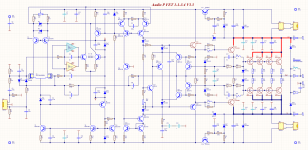
Basically, the BoosterPhone is a 4x gain-block (12dB), having an input impedance of ~10K, and an output impedance of a fraction of an ohm.
It is a class-B amplifier, inspired from the TracerPhone, but beefed-up to 7 transistor, and capable of operating at extremely low quiescent currents (80µA for the OP, 160µA for the whole amplifier) whilst offering a rail-to-rail capability driving a low-impedance load: with a 3.5V supply, it clips at 3.3Vpp.
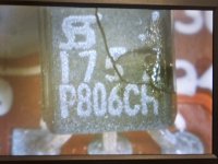
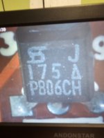
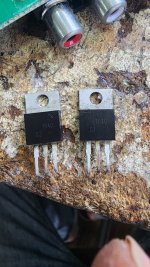
As usual with my projects, it uses exclusively the most common, jelly-bean type transistors: 2SC1815 and 2SA1015 for the signal part, and S8050 for the OP, all from the cheapest Chinese sources.
The output configuration is circlo-like, and uses same sex transistors.
The nominal supply voltage can be 3.5V to 4V, making it compatible with 3 NiMh cells, or a single Li-ion cell, which I opted for. I also included a BMS suite for the Lithium, to take care of the charging and voltage monitoring.
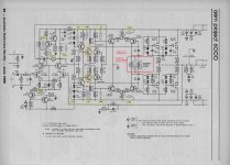
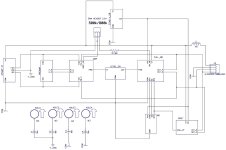
This is the schematic of the amplifier:

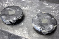
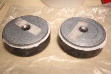
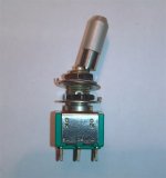
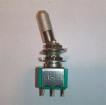
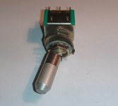
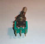
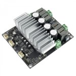
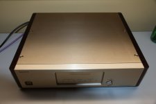
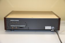
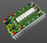
This is the finished Boosterphone:

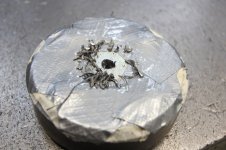
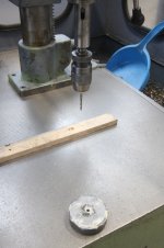
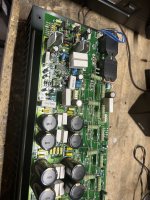
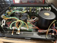
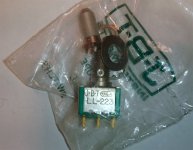
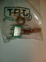
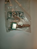
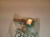
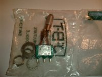
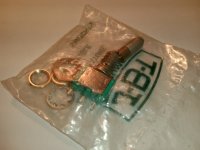
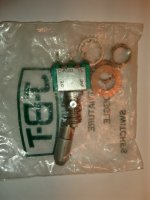
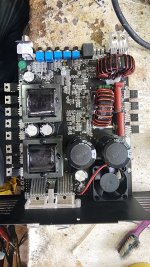
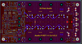
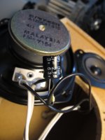
Some pics of its innards:


A pic of the output waveform, with a triangle wave. A hint of Xover distortion should be visible, but it is so faint as to be completely invisible on the photo: you need to look at the O-scope screen directly, with great attention to detect it (and you need to know where to look).

The clipping behaviour with a 3.8V supply (the bottom line of the graticule is 0V):

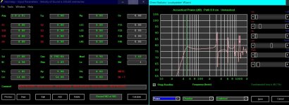
I also include a sim (not completely up to date)
As a result, they are hefty, power-hungry projects considering their smallish output power.
The BoosterPhone is the exact counterpoint of that philosophy: it offers decent performances, but not much more. For example, the THD is 0.1% and the full power bandwidth is 100kHz, which is OK but certainly not exceptional.
The BoosterPhone focusses on other aspects: convenience, practicality, usability and usefulness.
It achieves that by being a quasi-passive box, with only an input and an output and no controls.
It cannot be fully passive, unlike a transformer for example, but it is autonomous and so frugal and effective that it mostly looks like a passive device.
One of its most important feature is the absence of a power switch: the current consumption is low enough to leave it permanently On.
Its purpose is to raise the level of weak modern devices for low efficiency headphones or plugs, or to convert a line level into a low-impedance output compatible with a 32 ohm load. It was inspired by Daniel (danielwritesbac) who was looking for a simplistic solution for similar problems.
Daniel was more interested in pure line-level amplification, but this project can also work that way, by using a 100 ohm dummy load instead of the heaadphones.
My use is mostly headphone-oriented.
Basically, the BoosterPhone is a 4x gain-block (12dB), having an input impedance of ~10K, and an output impedance of a fraction of an ohm.
It is a class-B amplifier, inspired from the TracerPhone, but beefed-up to 7 transistor, and capable of operating at extremely low quiescent currents (80µA for the OP, 160µA for the whole amplifier) whilst offering a rail-to-rail capability driving a low-impedance load: with a 3.5V supply, it clips at 3.3Vpp.
As usual with my projects, it uses exclusively the most common, jelly-bean type transistors: 2SC1815 and 2SA1015 for the signal part, and S8050 for the OP, all from the cheapest Chinese sources.
The output configuration is circlo-like, and uses same sex transistors.
The nominal supply voltage can be 3.5V to 4V, making it compatible with 3 NiMh cells, or a single Li-ion cell, which I opted for. I also included a BMS suite for the Lithium, to take care of the charging and voltage monitoring.
This is the schematic of the amplifier:
This is the finished Boosterphone:
Some pics of its innards:
A pic of the output waveform, with a triangle wave. A hint of Xover distortion should be visible, but it is so faint as to be completely invisible on the photo: you need to look at the O-scope screen directly, with great attention to detect it (and you need to know where to look).
The clipping behaviour with a 3.8V supply (the bottom line of the graticule is 0V):
I also include a sim (not completely up to date)


![20231230_203747[1].jpg](https://www.diyaudio.com/community/data/attachments/1172/1172776-32c28ebbbc6088b37a63e2bd523762e6.jpg?hash=MsKOu7xgiL "20231230_203747[1].jpg")

![20231230_204231[1].jpg](/community/data/attachments/1172/1172777-a375a4acf93023c4ec1063e406b4e3b5.jpg?hash=o3WkrPkwI8)


