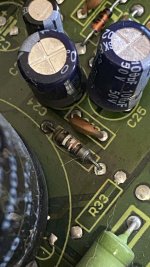
I have the same problem with Canton Ergo As 2 subwoofer as friend of @e_fortier from this tread https://www.diyaudio.com/community/threads/canton-ergo-sub-seeking-schematic.413258/. Andre from Canton after-sale service said that i need pay 200 euro for new amplifier, in my letter from 13 august, i try to explain Andre my financial situation, that i can't by new audiodevices, thats why i buy Canton 122DC from 90's and need to repair sub from 00's. Now after a week of waiting I'm confident that Canton do not provide me this information. I hope @e_fortier can help me with this.
I have long been looking at the Don Keeles CBT36 line arrays, but was intimidated by the insane amount of tweeters. Recently I happened to search for his work again when discussing speakers with a friend and noticed that now an other version exist, CBT24, that looks to be a somewhat easier build.
I am a bit new to the world off full-ish range speakers that benefit from a subwoofer. If someone has any tips for a matching subwoofer build I would be happy for advices 🙂 I will probably order parts from here: Audio Components
I have looked at these subwoofers: Seas E0026-08S W26FX001 and Dayton Audio RSS315HFA-8 12", should I have one or two subwoofer boxes?
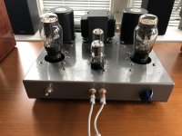
I just finished rebuilding this Rockford Fosgate amplifier and I have a thread going where I asked about proper bias current. I didn’t get much as far as hits on that thread, Nelson said 30 mA per device is “a healthy start”, so I am going to just set it there. There are 16 MOSFETs per channel so that would be .24 amps per rail, but sadly I can’t measure the rails unless I remove the large blue buss bar which I guess is and option.
So what I did is, I measured across one of the one ohm source resistors and adjusted bias until I saw 30 mV across that resistor which would equal 30 mA. Both channels perfectly even. Well one channel got quite a bit warmer. I checked all of the other source resistors and found that the voltages were all over the place, that’s when I found that these are not like emitter resistors on BJTs. On the cooler channel, the resistor I was measuring on was about the average most of them being in the 30 to 40 mil range while a couple were as high as 50 and some as low as 20 mV. While on the channel that ran warmer, the resistor that measured 30 was actually on of the lowest measuring, most of the resistors on that side were in the 50 to 60 mV range with a few at about 80 mV.
I’ve been doing some reading and I found others. They have had this situation and this shows the importance of matching your MOSFETs. So these people went back to their PB to get better matched sets. Well this is from the factory this way and I’m not gonna be able to better match 32 MOSFETs. I currently don’t have any spares of these models so I would have to buy a whole bunch.
So how would you recommend to best set bias on this? Should I just remove the buss bar from one rail? I could just make sure that the current draw on the positive rail is the same for both channels? I’ve read that the source resistor is generally the way it is done, but how exactly when the measurements are so different from each other. Do I just go for an average? Write down all the measurements I get for each 16 for each channel and average them out?
I really appreciate any help I can get with this. I don’t mess with mosfet too often, be a good learning experience.
Thank you for accepting me in this forum. I am an italian "aged electronic geek" and have always worked on audio circuits design, repair and a lot of electronic troubleshooting as well on both analog and digital devices since my teenage. I am sure I can find a big help here for my next jobs. I found very interesting the topic related to Hitachi HA-330 stereo amplifier, all the participats are so smart and prepeared. I will be soon working on a similar amplifier, the HA-250, having pretty the same circuitry, less power but with few big issues. I will soon post about it. Thank you again for now and can't wait to jump in the forum.
I'm posting this so that others can avoid any purchases from this company. Summary: Once I sent them money I never heard from them again.
This is a company that is supposedly located in Hong Kong. The have a very extensive web site. Looks legit, and so I thought it was.
I placed an RFQ via the web site's form, and got a reply email from a Mr Andy Lee with an official looking signature bearing the company logo. I explained what I wanted to order (some NLA Peerless drivers) and the quantity. He asked me for some information and then sent me a proforma invoice, with instructions on how to make a wire transfer to the company's bank account. I did that, to the tune of $1200.
I have only been able to contact Mr Lee once since that time, about 2 weeks ago. He confirmed that the funds had reached their account, and that they needed 2-3 days to get the items into their warehouse at which time they would DHL them to me. Subsequent repeated email to him, and to any and all other email addresses for the company on their web site have gone unanswered.
I can only conclude that I have been played as a sucker.
DO NOT DO BUSINESS WITH Micro-Semiconductor.com in Hong Kong!
More info:
Address: Unit 13 14F Lippo Sun Plaza 28 Canton Road Tsim Sha Tsui, KLN, Hong Kong 999077
Phone: +00 852-5107 1680
Fax: +00 852-5107 3140
E-mail: Andy@Micro-Semiconductors.hk
Website: https://www.Micro-Semiconductor.com
---------------------------------------------------------------------------------------------------------------------------------
Micro-Semiconductor.com is a global procurement organization providing professional, efficient procurement solutions to major OEMs and contract manufacturers worldwide. We specialize in locating Hard to Find, Obsolete, End of Life, allocated and long Lead Time devices.
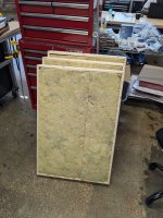
I'm starting to learn about speaker renovation and have a query about internal cabinet dampening.
I have three speakers each with differing materials and placements
1, Lentek S4 is a sealed cabinet and has thick Wool Underlay type material but is positioned only on the top/bottom and sides leaving a large gap in the middle
2, Celestion DL10 has a small port at the back (no tube) and is stuffed from top to bottom with white poly material
3, Wharfedale Linto 2 again a sealed box, has loft insulation type wool, stuffed, like the Celestions, randomly, but with not as much actual material.
I know that some reasons for positioning are down to listening preference but is there a default for sealed and ported boxes?
I noticed that the stuffing covers the port on the Celestions, that doesn't seem right to me.
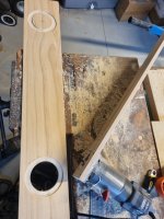
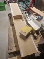
I'm just getting back into making speakers after a decade break, and starting with a small speaker bar to cut my teeth on first up. WAF has declared that "we won't have any huge unpainted MDF boxes in the house like last time", so focus is on honing my finishing skills before moving up to larger projects.
First in-progress pics. Made a simple circle jig (it's very satisfying to router a perfect inset speaker - a first for me). Now up to the super-fun sanding and filling stage...
Scott's design recommends SAE-F10 (felt), or jute for lining, but i'm struggling to source at a reasonable price down here in New Zealand. Has anyone used woolen moving blankets or woolen weedmat? recommendations appreciated.
We just re-arranged the living room and added a 65" TV sitting on a console. I'm thinking about building a soundbar to improve the sound over the built-in TV speakers. Doesn't have to be a huge improvement, my Medicare-aged hearing is not what it used to be. Has anyone here built the Markaudio CHN-50 simple 3-driver soundbar https://www.kjfaudio.com/wp-content/uploads/2021/03/CHN50-simple-3-driver-soundbar.png? If so, what do you think? WAF dictates that it be no larger than 5-1/8" high by 6-1/8" deep by 50" wide and very close (maybe 6") to the floor, no visible wires, etc.
Hello All, I have acquired a pair of Quad ii valve amplifiers. I know nothing about valve amplifiers so hoping to learn a little about them from knowledgeable folk here.
They're more or less original so need servicing/updating and checking before use. Any recommendations for somebody to do this would be appreciated, preferably within Scotland.
I recently finished up a 2a3 SET amp. While I'm quite happy with the results, I now feel like it's exposing other weaknesses in my system. My main complaint is that vocals (depending on the range of the vocalist, often middle to higher) are a bit grating to my ears and take away from my enjoyment when listening. What I'm looking for out of this thread is to hear what others might have to suggest. I have ideas of what I want to do, but I know many have been down the same road before, and I'd love to hear from practical experience. Thank you!
What I have now:
I currently have a three-way horn system that I put together 4-5 years ago and had been "good enough" for most of that time. It started life as a single JBL C34 with an 001 load. I found another C34 in decent shape, pieced together more components, and had a system that looked something like this:
DIY crossover build that is essentially just a JBL N1200 and a N8000 incorporated together using Jantzen CrossCaps, air core inductors, and L-pads that were affordable to me at the time.
I have some other components at my disposal as well. I recently picked up a pair of later Altec Valencias w/ 806As and 416-16Zs, both of which I've thought about building something new around. I have a single DuKane 10-cell horn (the 5A325) with a JBL 2470 mounted to it. I also have a pair of Altec A7 cabinets that need to be restored.
Changes I've been thinking about:
I know that the C34 cabinets aren't the strongest choice. I'm all for a DIY build for a bass cabinet though. Space is somewhat of a limitation, only because of the size of my home. The room is roughly 12' x 18' (3.65m x 5.48m), and the speakers need to go along the shorter wall.
I've played around with the Altec 806A's since getting them and I like how they sound, though the same issues still show up with a level of harshness that I can't seem to tame without sacrificing detail. Of course, this is just inserting them into the system I've been using, so they're crossed over at 1200hz instead of the 800hz they would have been in the Valencias. I also think I'd like to go in the direction of multi-cell horns, but size comes into play there.
With the 075's, I've wanted to sell them and replace with the 077/2405 for a while. One day soon I'll actually get around to it.
As for crossovers, I'd love to keep it DIY for cost purposes, but I've also been eyeing Werner Jagusch's for a while.
Now take my selection with a grain of salt…..i‘m sadly a realist that understands a 4” driver is neither a woofer or tweeter and therefore response below 100hz or above 10k is not considered. YMMV
I was not sure if to post this into "analogue source" or "tube section" of the forum, so admin feel free to move this where it belongs 😀
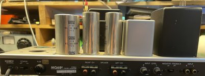
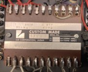
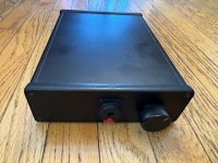
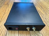
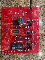
Based on my previous tube riaa phono preamp with passive correction I wanted to build something a bit better. I was very satisfied with the previous one, however as I was building new line preamp, I wanted to match the look and also performance of my newly built tube line preamp. So I took a challenge and tried to upgrade the RIAA and tried to make way better, the best I could, and I did!!!
A lot is very same as in my line level preamp, all the mechanics, shielding, pcb layout and power supply. So if you want details go to check that one. The main difference here is, the PSU works on higher voltage and is even more filtered with CRC (22mF+1R+22mF) for tube filaments and CRCRC (3x220uF+2x470R) for tube plates. All regulated with LDO regulators with even higher capacities, everywhere further filtered with polypropylenes etc. As cathodes of some valves are quite high here (+150V) I had to elevate heater power supply, this brings a small complication as extra transformer winding is needed for powering controls, relays and timers.
RIAA
I wanted to make it kind of voodoo-hi-end sort of, in a sense some things may not be fully in line with what I believe is necessary, but I did it anyway to make it the best 😀
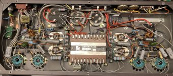
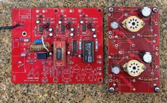
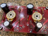
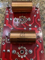
In the input stage there are three ECC803S triodes connected as u-follower. Two parallel connected triodes creating input and one as follower on top...
The only biggest disadvantage of this solution is very high input miller capacity in range of ~300pF, but as this value fits majority of MM pickups I took this tradeoff for very low noise, higher transconductance and gain. The output follower feeds passive RIAA network thru Mundorf Oil cap 🧙♀️I was able to design correction so precisely in one go, that I have reached +-0,1dB RIAA error in 20Hz-20kHz with -2dB@80kHz. I have implemented also reed relay switch to have possibility to change correction to "somehow" get close to what is called as "IEC RIAA", well its not exact in any way but makes -3dB@20Hz, sort of "rumble filter" or so. After the correction, there is simple amp stage with ecc803s feeding the white cathode follower by E88CC to easily drive line level loads.
I know I know, for "low noise I should use hi-mu valves" at the input, but in my testing the gain was not sufficient and noise very much matched gain, so lower gain lower noise but then had no gain... so I decided 83 (12AX7) would be the best valve for this. I tested like 50 different tubes here (several ECC88,85, ECC83 RFT, 6N2P etc...), long story short - only the ECC803S are usable in terms of low-noise and microphonics in gain I needed. See the picked "premium" 6n2p noise compared to RFT ECC83, just on open bench, no shielding:
For simple on/off and mute delay I made separated control board. Nothing special...
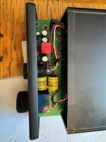
Below a few pictures from the build:
and more...
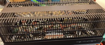
Case and mechanics as I explained follows my previous build, but in short... there is tripple shielded suspended and potted transformer, floating style pcb placement with both sides full access = the heaven for modification 😀 etc... what I added extra here is the "dampener" for tube tops, (inspired from mcintosh preamps 😀 ) not that it was needed as ecc803s are absolutely not microfonic in any way, but just for better feeling 😎
To be able to properly measure and test, I built inverse RIAA passive network in shielded box:
the QR code was maybe nice idea, but then I realised its wrong so need to print a new one 🤣
Then I've created custom calibration in REW for it based on mathematically exact RIAA curve and measured preamp correction error which looks like this:
and finally, fully covered preamp spectrum measured...
overall gain is 46dB which is on a higher side for phono, however usefull for low level MM pickups at least. Below is 5mV input, 0dBV calibrated output into 10k load (buffered cosmos adc). With higher output pickups output it will get easily to over 2VRMS which futher loweres the signal to noise ratio...
Please note there is no negative feedback loop in this preamp!
speaking of noise, input shorted with 47R, output directly into cosmos adc, 0dBV calibrated below:
note the mains noise here is non existent = battery like power supply and this is with +65dB gain @50hz😎
and at the end... how it sounds...
well, good 😀 not that I can recognise the difference, but measures nicely 🤣
The noise is different story tho, I have never ever heared tube phono with so low noise. You can dirrectly connect it to power amp, turn volume to max. and hear just very tiny hiss.... this is absolutely mindblowing to me as compared to others tube phonos, which sounds like waterfall compared to this one...
Some companies ship drivers with shorting wire twisted across the terminals , some don't.
Tapping the surface of 3/16" masonite covering a 15" woofer in a cabinet it's very easy to hear the difference between when shorted and when not. Deeper and looser when open, tighter and higher when shorted. So undamped and damped.
The question is, is it better to short them when shipping or not?
OK, I know this may be a bad idea...but if simple and does what I hope and does, and not damage my mixer or amp, all good....yes?
Got this little problem...built an amp (actually two - one SS and one Tube- 12AX7 to 6V6) I am happy with...they sound great...but I mic the amp (Sennheiser e609 or SM57 mic) to a mixer, I get drowned out by the other guys in the band...my guitar sounds weak in mix and over the PA system...
I have played with the mic levels on the mixer (Behringer X-18) and just end up sounding worse...reducing the other instrument mics to mixer also not working out. I would like to try sending the Speaker out to the Mixer with a converting circuit. I have a few Sescom 10k/600 transformers, 600/600 transformers, resistors, caps, etc...
I don't want to do this off the Send/Return (off preamp signal) as it will miss the rest of the amps effect on sound.....If I can just add the Mic XLR out to the amp and lose the mic all together, that would be nice.
Thinking a voltage divider off the speaker tabs and then to the transformer to an XLR to mixer....any advice?
I am working on a friend's amplifier, Messa Boogie (Solo Head). He said the amp sounds dirty. What I noticed is that, there is severe crackling, popping and weird noises from the amp even without any signal present. It is present on all 3 channels. It gets worst if I turn up the volume or gain on each channel. I have isolated and checked all the electrolytic and orange caps, they are all within range. I did not check the tiny (picofarad) caps. I tried replacing all the 12AX7 tubes , one at a time with a good working preamp tube with no difference. Cleaned all the pots, switches and sockets with contact spray. I totally have no idea what is causing this problem. Can someone please guide me on what can cause such problems and what to check for. Schematics attached.
This volume knob is history. The blue plastic insert has a notch that aligns with the hole in the aluminium cover but it's incredibly difficult to get on in one movement.
The factory glue had perished leading the cover to come off so I tried to hot glue it in place but failed as I could not get the nodule in the hole before the glue dried. I then had to heat it up in order to remove the insert and it deformed completely within a very short time.
I'm so annoyed. The amp is an Azur 550A and is otherwise in top condition. I'm hoping to get a new knob but failing that, any suggestions?
Hi everyone, I'm a software engineer from Sweden with an interest in everything DIY.. electronics, home automation, audio. The list of non-finished side project goes on 🙂
Found this forum which seems great, hoping to learn more about audio.
I have a lot of these SIC diodes, rated 600V. I would like to use them in a diode bridge instead of the 1200V SIC diodes I usually use for a 350V B+ supply.
So I need equalising resistors. What value and wattage should these be?
Do I need caps as well? If so what type and value?
I'm considering using an old laptop power brick for a simple 12AX7/6BQ5 SE amp. 19V and 7 amps to 250VDC for B+ and 6.3VDC for the heaters. I am looking at a switching AD/DC converter for the B+ (I am told the switching frequency is well above human hearing), and a DC-DC LM2596 buck converter to get the 6.3VDC for the heaters.
The buck converter is rated at 3A, and I believe that should be fine for the 3 tubes involved.
However are there any considerations I am missing?
My gfp-565 turns on but I have no signal on any of the outputs.
I can hear the headphone output.
I don't hear the realys activate.
Any clue where to start?
thank you so much.
javier astorga from argentina.
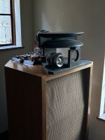
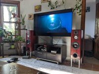
I want to thank everyone here that helped me out as I definitely could not have complete this without all your help. At least not to the level of polish that it is what it is.
A special thanks to A4eAudio for guiding me through this. He gave me a lot of one on one help and I don't think I could have navigated all the software without him.
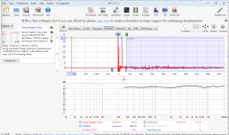
The REW screenshots show the end measurement far field. I am using the IR window to show with and without reflection to I can show how flat the frequency response ended up. The second REW measurement is all the way down to 40 hz. By then the reflections of the room have taken over. I built some acoustic trap to put on the back wall so that should help. The traps are 4" rockwool laid on top of acoustic underlayment. They will be placed 2" from the back wall on stand offs to help trap the lower frequencies.
As you see in the first pic I am using these in my main living room. I am not used to having this good of imaging so am getting used to the fact that I can now hear, for example, the singer on the right, the bass player on the left, and that the drums are more left and behind both of them. My buddy mixes music and says these have the best imaging he has ever heard. I never once took imaging into consideration of my design so I guess its a happy accident. If anyone knows why these have good imaging let me know so I can replicate it in future designs.
I am running them off a WIIM amp. It sounds very good. I also bought a brand new receiver to try out but that thing sounds super flat and not very musical so it will be going back to the store.
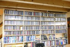
Several times in the past I have gone down the path to rip all of my CDs to a hard drive. I have never finished the task, or even gotten very far. Now after collecting CDs for 35+ years, I have a few. I also have a few computers, so I got a NAS box with 20+ TB of storage, so here I go again.
My earlier attempts used EAC which can take some time to rip, so this time I am using the older version of Windows Media Player which can rip a CD in 2 to 7 minutes. Why the difference in time on unblemished CDs with roughly the same amount of music, I don't know, but I'm guessing Windows background tasks slow it down. I am ripping directly to the NAS box with all the other connected computers turned off or disconnected. Unplugging the ethernet switch from the internet modem does not seem to make a difference and it blocks the Media Player from downloading the song titles and musicians' data.
If I get through the 1200 to 1400 CD's there are 600+ Vinyl records on the bottom two rows of that cabinet and they must be ripped in real time! The DVD movies below the CDs will not get ripped.
A friend of mine had a few thousand feet of surplus high quality microphone wire. I've read posts here and elsewhere that say this can be the basis for high quality speaker cables, since mic wire has very good shielding. My friend did the 6 wire DIY braiding method and gave me a couple 8 foot lengths of completed cable, which I finished with some excellent banana connectors, some woven poly sheaths, and heat shrink to tie it all together.
The problem: I've noticed that speakers hooked up with this wire demonstrate some odd effects. It's hard to describe but it's like an intermittent clicking or popping. I have a failed volume control on an old preamp that starts injecting a similar noise when I go past one-third on the dial. It's very short duration and almost subliminal, but once I notice it then it doesn't go away. There's no pattern to it but I think it's related to transients in the music because it's usually at the attack side of a given sound and not the decay. It's almost like tiny bursts of DC are getting injected into the sound.
I'd hate to waste this cable. Is there any kind of test I can run to find out whats happening here, and is there anything I can try doing that might help the sound?
Hello everyone, guys! Tell me, does it make sense to replace the operational amplifiers at the I/U stage and at the LPF stage? If so, which ones would you recommend?
My Rotel RB970 BX mk II has been in use for 20+ years now and has recently developed a crackle on the right channel even when no input is being sent from the pre-amp. A long while ago I did open it up for a general dust and noticed some corrosion (or leaking?) around where the four big capacitors sit on the board. I'll try to dig out those pictures.
Any thoughts on what has suddenly caused the crackle to develop?
Is it likely to be terminal?
Thanks!
Many years since I've posted here. Had a quick question in another post but the Forum asks I re-introduce myself first. 🙂
General interests that come and go. I've recapped a few 1970s Marantz, built several tub amps from kits (TU-8200R & 8600) and one from scratch, a "Get-Set-Go" SET with way too much 120Hz power supply noise. More recently interested in waveguide speakers and recently completed an Econowave with selenium 220Ti, Jack gill crossover to FiatalPRO 12PR320. .... Many interest, but mostly just restore old MGs.
Looking forward to continuing the learning process. Always lots of fun!
Hi there - long time Hifi owner/user. I searched for this forum after recently encountering a problem with my Rotel RB970 BX power amplifier, and am hoping to get some suggestions on a fix.
Hi all - looking for some reference schematics for solid, decent headphone drivers that aren't overly complicated. Would prefer op amps vs discrete design for simplicity.
I'll be building myself a small mixer/headphone amp, and would like to see what some of the better headphone solutions are these days.
I've used the Behringer P2 on lots of gigs and it sounds fine to me, but I'm not finding a schematic easily. Any ideas on this or similar headphone drivers? (this would be for IEMs in particular; I imagine driving cans is maybe harder, because the larger speakers might require more oomph?)
I just opened the latest issue of AudioXpress and on the last page there is a PE advertisement featuring all the members of the ULTIMAX II subwoofer line. This includes drivers of 8, 10, 12, 15, and 18 inches nominal size, all with very impressive Xmax specs (up to +/- 28mm for the 18" driver). The VC configuration seems to be dual 2 Ohm for all versions. At a glance this seems like some new and interesting stuff from Dayton and so I thought I would fire up a discussion thread for this new driver line.
If you have news/info on these drivers, or when they become available you have first hand experiences to relate, please post them here!
Does any of our friends in Germany, and elswhere for that matter, know if this company is still operating? I have tried calling and mailing for several weeks, to no avail.
They have phone and mail listed on their website, but no reaction.
Hi
Okay I should have taken pics before dismantling! Doh.
On each of the drivers and the tweeter of the above, there is one red dot sticker on the magnet next to each connector spade.
Can I assume that this indicates the + terminal?
I can test using a battery but don't know how to test if I have the tweeter wired correctly?
I'm living in Richmond Hill, and hoping to dive deeper into my home audio set up.
The biggest part of my journey, a pair of Klipsh Klipshorns KC-BR (from the late 80s or early 90s) that I inherited from my father. Ever since I was a little child I was absolutely obsessed with them and in beyond happy that I now have them in my possession.
Crossovers were delivered wrong on the factory speakers. A quick fix involves just a few simple steps. Your jaw will drop when you hear the difference!
1. Open rear cover plate on speaker. 4 screws.
2. Pull out gently and note the crossover is attached.
3. Solder a shorting jumper over the sand resistor 3R3.
4. Cut thin red solid wire and solder to Heavy red wire's solder pad.
These actions do two things:
1. Over-ride the attenuation blocking action of the 3.3 ohm resistor, thus allowing the mid tweeter to open up.
2. Bypass the awful 1.8uf bipolar electrolytic capacitor that is in line with the ribbon tweeter. The ribbon does not need the cap at all and now it is directly across the primary speaker leads.
The Philips MCD-908 stereo system came out in 2007.
What you will notice when you re-power your speakers is a bright and full spectrum of sonic harmony. Especially in the ribbon tweeter which is now operating as intended!
A compact stereo amplifier based on the TDA2050.
SMD components were taken from TV boards.
The circuit board is from an old project of mine, I had to cut to adapt.
I managed to buy the CD2050CZ manufactured by SEMICO.
These are the printed circuit boards I had to adapt.
Just wanted to introduce myself, Dubcraftee. I have many years of experience and repairing vintage audio as in '70s and earlier solid state and tube alike. As well as building tube amps I thoroughly enjoy modding and fix cars as a living. Thanks for having me
Having the chance to buy a pair of 4590 locally, I am looking at how to use them. BMS boasts a recommended 300 Hz lower crossover, which looks great on paper. However, even with the famous 90 x 6 BMS horn that was discontinued about the time the 4590 was launched, frequency response starts dropping at 700 Hz. In extrapolation, this looks like it will hit -18 dB at 350 Hz (!). So unless one uses a custom built very long horn, the 300 Hz recommended crossover will only work with a massive active boost.
I have been reading that most people use the 4590 only down to 800 or 1000 Hz. The treble unit of the 4590 seems to be a poor compromise with plenty of distortion and poor integration into wide horns. Apparently, the Limmer 033 works well with this driver but will only be good down to 1 kHz.
On the other hand, people have been using the lowly BMS 4550 down to 800 Hz in home settings, and a larger driver like the 18sound ND2080 (it's the 1480 without the adapter) should be good to at least 500 Hz while offering reasonable treble (and then there is the NSD with even better treble). I'm guessing here that a 3 in dome will have more oompf down there than a 2 in annular membran...
So if the aim is to have a horn/driver combo that covers most of the midrange, starting at 300 - 500 Hz all the way up to 20 kHz, is the 4590 really worth the trouble?
i'm working on my F5M an i have to think after....
the F5M will drive my pair MOAP 10.2. actually i have a computer with a soundcard behringer as dac but it's not friendly for the user. (my wife and there is not remote control)
i have to think to preamp/DAC/streamer, i was thinking to buy a Wiim ultra to make this
but my goal is to have emotional engagement from my system, what do you think of this
average all the music is digital CD or demateralised i use average no phono
i listen most of the time pop rock,alternative, piano, and electronic music
what do you do if you were me?
Hi All,
Ever since joining this forum class B auto-bias has been on my mind. Thanks to Russel Kinder's RK-Auto200 design.
Russel helped me along massively in solid state design when I was a newbie here. Only at the time I couldn't make sense of his autobias schemes.
Yesterday I think I finally conjured up a circuit that does the job correctly.
I set out to find a circuit that:
Replaces thermal tracking. Forming a subsonic bias feedback loop that compensates for thermal drift.
Maintains the bias current even with full power 20 Hz signals.
Should bring the bias up, such that before the bias feedback starts acting there is no bias current and all remains safe.
Leaves no signs of its presence opposed to a passively biased output stage.
What really cracked my brain was howto detect the bias current under large signal conditions.
It is known that the class B signal currents cross at the bias current. So some circuit should measure what current is present when I(R24)=I(R23). I guess this is what is referred to as "Zero Crossing Detection".
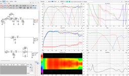
Yesterdays contraption seems to pull it off:
Two current mirrors Q37 to Q42 forming the sensor circuit sense the bias current through 0.22ohm Rsense.
The top mirror subtracts I(Rsense)*Constant from I(J3) while the bottom mirror adds I(Rsense)*Constant to I(J3). This constant is set by by Re and Rsense. The output currents of the two mirrors are added onto Rc to create voltage V(Rc) which is proportional to bias current (and signal current).
Current mirror output currents Ic(37) & Ic(q38) summed to I(Rc) creating V(Rc):
Now under class B signal conditions the magnitude of the V(Rc) peaks are proportional to the bias current. (some kind of personal revelation to me🤣)
This is where the peak detector comes in. I've tried single and dual opamp active peak detectors, all left some artifacts in the FFT. Passive does not. So I Simply implemented it with D11 and C11 to create V(vpeak):
Next V(vpeak) is fed to an integrator (U4 TL072) that compares it to reference voltage Vset. In this case -4V, being the target voltage for Vpeak.
Now the bias current can be defined by Rsense, Re, Rc and Vset. Rsense Re and Rc set the gain of the current mirror sensor circuit, the integrator should make all the rest irrelevant.
The integrator then drives an opto-coupler to engage the bias-spreader. More opto-current results in more bias and no opto-current results in no bias. This should be true even when the output stage is getting boiling hot.
Now the loop is complete and it seems to be pretty sturdy but I'd like to make it sturdier. Unfortunately the bias does drop (10mA or so) when a 100W 20Hz signal kicks in. It never quite gets back to where it was but at least we see integrator trying to bring it back up:
Then there is the issue of loop stability. Depending on the Gain of the sensor circuit, the integrator time constant and C11 (probably many more), very low frequency oscillation may occur. Its damped ok now but id like to know howto properly compensate it. I haven't figured out howto do proper stability analysis on this.
The integrator output current in response to large Low F signal:
The output current dropping indicates the integrator thinks the bias has gone up so it drops and we loose some bias. It seems to still misinterpret large signals for bias fluctuations but only a little bit. The loss of some bias current I attribute to the non-perfect Sensor circuit and the passive peak detector. Perhaps there are other causes. Perhaps it needs one more op-amp after all. Perhaps this is accurate enough. Most important is that the bias doesn't keep falling or shoot up like many of my other tries. Neither does it leave anything sign of existence in FFT's.
Hopefully I can breadboard this in the following days. I'll probably waste more time simulating and considering:
Sensing from the Emitter resistors opposed from collector resistors and making the circuit float with the output.
Eliminate the opto-coupler and use Q19 and Q20 current sources to control the bias.
Greetings! I am a musician and hobbyist electronic "engineer". I like projects around microcontrollers, especially, when they are related to music or music instruments. Not afraid of disassembling a synthesizer 😀 But still, quite new to all of the electronic components. Did few POCs around MIDI, LEDs and EL-wires. Have some ideas to implement and need advices and opinions, that's why I am here!
I have some custom made wood amp cases with carbon fiber front and rear plates that I am installing my Icepower 125asx2BTL, and 50asx2btl amps in. When I had the amp modules in a metal case I hooked up the btl to the metal chassis and then hooked up the ground from the ac plug to the metal chassis too.
Would it be OK to hook the btl directly to the ac plug too...the furthest amp module will be within 10" from the plug?
Can I daisy chain the btl wire from 1 amp to the other and then hook the 2nd amp module to the ac plug, or would it be better to run unequal ground lengths from each amp module to the ac plug?
Or is there a better option (without making a new case)...
For sale is this set of AN dac boards. I upgraded to DAC5 and do not need these.
The analog board has the Tantalum resistors, large AN input transformer and the later model AN copper foil caps,
these are not the early ones that were prone to leaking.
This set does not come with the IV transformers however there are several good ones available.
These take the 5687 tubes in both positions and has coax and USB capability.
The input can take 48k & 96k via USB and there are receiver chip mods for higher fs inputs.
BTW- I have my DAC5 setup with a 768k XMOS to i2s and run at 706k which is just awesome.
Asking $300 for the set.
I also have a new unused populated Galahad PS board clone with if anyone is interested for an extra fee.
Al bit silly, but I'm stuck. I'm building a streamer based on a Pi, and I need to extend coax, optical and I2S to the back panel of the enclosure. I'd like to buy prefabricated extensions of good quality, but for the life of me I can't find the right search term.
Could someone steer me in the right direction please ?
I have been a secret / anonymous reader of this great forum for a couple of years now.
Most of the times had nothing to contribute but had a lot to learn from this amazing community.
Whenever the magic smoke escaped from my stuff I ran to this forum to learn how to put it back.
So far all escaped Jinie's been caught and hope that goes on.
As long as wife and children can keep up with increasing pile of junk ( in their opinion ) I shall hold the post of a certified Audio Stuff Hoarder.....
Hi. Here for sale a pair of THF-51S TOKIN SIT, Rough Matched pair (no matching curve), Condition: New – Open box, Bought directly from Japan one month ago, ebay seller fet-tokyo, known to be a trusty guy, parts, never used, never soldered.
Paid 198U$ + 24.80U$ shipping, total 222.80U$, Change of plan I cannot build the amp I was planning... My lost, your chance to get a pair at the good price...
Asking 150U$ + shipping (should be around 15U$) + Paypal 3.5% fee (or use Friend & Family)
I want to present you another autobias project. This version we built is designed to work with the Hawksford error correction published in Bob Cordell's book. The principle of operation is based on the patent US4237425 by David A. Spiegel. This principle was elegantly implemented by Shinichi Kamijo at http://www.ne.jp/asahi/evo/amp/J554K2955/index2.htm
when looking at 300B builds, some use holes around the socket of the tube and some do not.
The argument made is that these holes will produce air flow around the tube in some "chimney effect". I am sceptical that this has any significant effect, especially if the case is closed at the bottom, but even if not.
Are there any real measurements available that prove the chimney assumption?
Also, the tube has a heater / filament to, well, heat it. So, given a design with some room around it and a grill/mesh above / around it at max, is it even desired to cool it?
has anybody tried these for single wire to board connection .
Where you have only 1 solder pad to solder wire. I cant seem to find
a one pin connector for single wire. Need something like a one pin one wire,
all the one wire connector's seems to be like b with 2 pins one behind the other.
I want single pin as i don't like to solder wires direct to pcb for easy alterations.
I also find that soldered wires to pcb are prone to failing.
Thanks
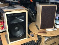
I have a pair of Celestion DL10 to my ears they sound great but I don't think they go for much on the 2nd hand market.
I will be selling them. But I can't make a decision on m, the two options below.
1. Replace the caps, clean check soldering, reseal, check wadding, and replace grill cloth. <£sell?>
2. Strip out current components (drivers, cabinets, crossovers tweeters. All original) and sell them individually. I should say that the caps don't look like they are past it 🤔 <£sell?>
where is the demand for either option? is there such a thing as a Objective view point?
Hello. I have a pair of the tweeters for building Spirit Winds. Mr. Bagby is sadly gone, and so is Meniscus Audio.
Can anyone help me with the xover for the Spirit Wind speakers?
Thank you.
I made 2 amplifiers using the red Sanwu tda7498e boards that are available at all the usual places. I'm using one with a pair of 2 way bookshelf speakers with 8" woofers made by TC audio and the other with 6.5" woofers and 3.5" tweeters. They both have developed a pretty loud noise floor that I never noticed so loud as it is lately. I can hear the static white noise sound from 8' away when it's quiet in the room. They both hiss even when the signal inputs are disconnected. What would cause this to happen?
Also I remember reading about some popular mods to these Sanwu boards but can't seem to find the thread anymore. If I remember correctly one of the mods was to remove and jumper some diodes but I don't know which ones.
I have an opportunity to buy some Bear Labs Mosfet SE monoblock amps for a decent price. These amps were build by a long time member here, Bear. I believe Bear is gone now, and this is all I can find on the amps on the interwebs: http://www.bearlabsusa.com/NEXT/SPECIALS.html
Does anyone have any experience with the amps? I would use them in Joseph Audio Profile floorstanders. How much would you pay?
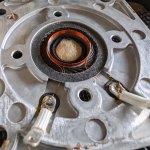
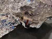
So, I'm having this really weird behavior from a sub I just rebuilt:
I was breaking it in with a sine wave at Fs for the whole night, and at the morning it suddenly started doing a cackling sound, characteristic of a misaligned voice-coil rubbing against the top plate.
I then switched off the amp to see in what direction it was misaligned, but as soon as I switched it off, it would no longer sound like it was rubbing on anything, even if I forced it to tilt with my hands, by applying more force to one side than the other. Seemed very properly aligned.
Then I figured it could only be because of the amplifier being on, I switched it on, and it began doing this rubbing noise when moving the cone.
I took it off from the amp and shorted the voice-coil, and again, it began doing this sound.
So, whenever there's a low-impedance circuit closed on the coil, it does that.
But my question is: WHY?
I don't understand how more damping can cause the voice coil to rub against the walls.
The only thing I can think about is that, when I'm pulling it by the cone with my hands, and the voice coil is shorted, the damping force on the voice coil is misaligned with the force the cone is imprinting on it, and the resulting movement is skewed.
But then again, the weird thing is, that no matter to what radial direction I force it, or tilt it, this rubbing sound never goes away, never improves substantially.
If I force it even more, then another, stronger rubbing sound comes on, making it even look like that only then it's actually rubbing against something.
I don't quite understand why this only began after hours of operation, perhaps because it heated and softened the glues, but the voice coil didn't even felt substantially hot either.
I'm just worried I'll have to rebuild the entire thing just because of this.
And by the way, it's not quiet enough to be ignored, it's clearly audible.
I'm revamping my Tubelab Simple SE build and I'm currently laying out the top panel. Does anyone know if there is a drawing (CAD, dxf, fpd, etc) that has the layout of the board to get the drill holes correct? I've found a pdf but it isn't easy to get the exact layout from this.
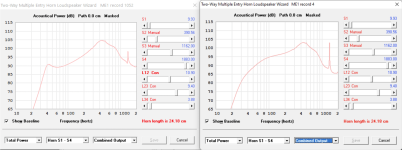
Looking to swap the B&C 10nw76 drivers for 10cl51 (saving nearly 2kg per driver) and the DCX354 in place of the DCX454 he uses, saving another 2kg... a total of 6kg saving!
I used his parameters in Hornresp, but with he 10cl51 specs, and got a plot with similar or better SPL from 55Hz upwards. See image below. Left hand side is the plot from Scott's instructions with the 10w76. Right hand side is my plot with the 10cl51 specs.
I know the 10nw76 has more power handling, but I'm limited to 150watts, which is the max my battery powered TPA3255 amps will supply per speaker. I'm happy to pair with a sub and/or use a bit of DSP to fill in the bottom end (with boost, or psychoacoustics)
Am I missing anything? Any issue crossing to the DCX354 at 400hz, instead of the 300Hz possible with the larger DCX454.
Thanks!
(PS: I know this is heading in the direction of the SynTripP design, but I found Scott's instructions more complete and the rear ports seem to me to be easier to 'play' with as I'm experimenting with different drivers and tuning)
Hi everyone just joined for this after MANY results on google landing here.
So the story is I have my Pajero aka Montero Sport 2005 which I like, doing sound at the moment.
Here is my budget friendly setup I have:
KDC-BT73DAB head unit
Hertz Cento C165 speakers (front and back) freq 55-7k rears faded to half
Alpine S-S10TW tweeters freq 1 kHz - 22 kHz
In Phase USW10 Under seat subwoofer freq 40-150hz
I have tried many tweeters including the focal ones, anything else but them alpines are way too harsh for my taste even with eq settings spent hours get some songs right then others wrong. These Alpine S-S10TW are perfect for me.
I also have a set of 4x Audison Prima AP 6.5 freq 60 ÷ 5k Hz
Since I have a sort of a subwoofer (not the best but does the job) is it wiser to use the Audisons since they have lower bass and mids up to 5k?
Also, obviously the tweeters are overlapping with the speakers on the 1k-7k range. IS that ok or should I somehow limit the lower range and put a filter for them to start at 7k?
The hertz speakers are very good with bass, the seat subwoofer is set to 60hz and it sounds ok. The sound quality however is just not right to be fair, I had my freelander 1 from 2003 with harman kardon mopping the floor with this. That is what I am aiming in fairness I do not need nor want loud, just SQ. The subwoofer under seat was put there to help with bass whilst driving... That is where bass goes away evaporating.
Ah yes all four doors are properly sound proof, both inside the panel and the door itself with dynamat outer and some soft 3mm inner, not a single rattle anywhere. That part I am confident it's well sorted.
I would appreciate a bit of insight into this, if anyone here knows:
1. Vias lining a PCB trace - impedance change: How do the GND connecting vias lining both sides of a PCB trace (digital traces in particular) change the impedance of the PCB trace? Since the electrical fields surrounding the PCB trace is altered when adding these GND connecting vias to each side of the PCB trace I would guess that it also alters the PCB trace impedance, however, I have not been able to find any mention of this anywhere ... ? Anyone knows about this (I would also much appreciate a link to a short text describing the optimum way of placing these vias, should one of you have such a link)?
An example of what I am thinking about can be found here:
2. Crosstalk differences: Also, I have been wondering to what extent such vias alter the crosstalk between traces? ... Robert Feranec in one of his youtube videos (a trace radiation simulation without vias is shown from 15:13 - with vias from 16:03) illustrates how these lining vias greatly reduce the radiation from the trace - something that I reckon will also greatly reduce crosstalk:
Login to view embedded media
However, when e.g. using the Saturn PCB toolkit (v. 7.11) the crosstalk numbers appear to be relatively high (and it is not described in the tool kit help whether or not lining vias are considered in the crosstalk calculations) ... That the Saturn crosstalk numbers appear to be high is my "assumption" as e.g. Analog Devices in their layout of the AD4630 EVM board's input traces according to the Saturn PCB toolkit would have a crosstalk coefficient between the two input channels of ~ -116 dB (1 MHz sine wave=~350 ns rise time, 10mm trace spacing, 10 mm trace coupling, trace-to-gnd plane distance 0.2mm, FR-4 board, signal voltage 5V). Which is quite high considering that this ADC is capable of a much lower noise floor. A link to the AD4630 EVM board - just FYI:
So I wonder how much lining vias - which are lining the AD4630 board's input traces and also discussed in the Feranec video - alters the radiation from a trace and thus also the trace's impedance?
BTW in searching for this information on Google I found an article on guard rings in microstrip & stripline PCBs. Quite interesting IMHO.
Hi all - I've been involved in DIY for over a decade now, building various kits, speakers, headphones, etc. I'm planning to build my first non-kit amplifier, starting with the Tubelab SSE. Looking forward to chatting with all of you!
Hi all, I am looking for 10 or so replacement gold Pcb mini spade pins and edge connectors for boards in my Naim NAC 72 Amplifier. Does anyone please know where I can find them? (I’m based in UK / Europe). I’ve hunted everywhere unsuccessfully so far. Thanks for your help. Adam
Hi All, I am trying to understand why in RH84 amp by Mr Kitic vast majority of builders employ tube based rectifier?
Why not to use modern fast Schottky diodes + MOSFET based precise voltage stabilizator?
Pros of my way of thinking would be:
1.dead silent power supply.
2. voltage stability independently from mains voltage swings
Is there any consensus on what makes a good quality tweeter (other than correct implementation and Crossover design)? Please excuse my lack of knowledge but there is a huge range of products out there. From foil to dome, metal, silk etc. Is a larger ferrite motor preferable to a small neodinium one?
What could I expect if changing an existing tweeter with a marketed as high quality item one of the same electrical specification and am I correct in assuming that even something as the wave guide will have to be taken into consideration at crossover design and can't just be added to a speaker as a replacement later on? Thank you
I have a small stereo system consisting of an F5 amp, a Korg Newtube preamp, an old Rotel RP1000, and Frugal horn speakers with Fostex 4" full range speakers. I love my home build stereo. It is best when played with records that are recorded the old way with a band around a mic. Miles Davis Kind of Blue is one that sounds best. Live recordings sound great. Anything that is well recorded sounds good. Bad recordings are really exposed. The system's weakness is on the low end. These speakers cannot reproduce full orchestra recordings very well. The problem is not what sound comes out of the speakers, it is what is missing on the low end.
So, what speakers would you recommend that I build next? I need speakers that will reproduce big complex recordings that include a lot of base. I do not think adding a sub will work well with my current speakers. I have the tools and capability to build fairly complex cabinets if necessary. I will not add store bought speakers to my home built stereo. I would get sent to hell for a sin of that magnitude.
I do not have a huge house or an unlimited budget. WAF score will be a factor, but she loves my stereo so far...
In this video he demonstrates the potential that exists in every home between your neutral return and your homes safety ground. There can be several volts, and it can vary based on what is currently drawing power in your home, as well as differ at various locations in your home if you measured it at various outlets. Thought I'd post this as it shows the reason for ground loops, why people incorrectly try to circumvent problems by lifting safety grounds, and why we devise methods like the 10 ohm resistor with capacitor and
diodes that only engage if there is truly a safety fault (see the tubecad "house ground" circuit) to get a audio ground reference that is also safe. Nice short video, for a subject that mystifies.
I used to think they had a couple models that were tempting but the paint is peeling off now? Login to view embedded media
And that is on top of the lack of a simple transponder key leading to people's cars being stolen over and over. And don't even get me started on the 'fix' for the brake fluid leaking on a wiring harness being putting a lower rated fuse in so it will blow before the wiring harness catches fire. Shouldn't the leaking part be replaced?
Have had a discussion about fuses in the preamp….
My thinking is:
The preamp fuse is dimensioned for the inrush current during start-up - thereby probably largely oversized for the preamp after the start-up period. So what is the purpose of the fuse?
For protection? But the house electrical network has fuses…. Isn’t that enough?
Can you please explain to me why is it necessary to have an preamp fuse? Is the fuse really nescesarry ?