Rare REL capacitors! 0.47μF and 0.1μF

A very rare chance to get some very good capacitors at a fraction of their original cost.

4PCS NOS 0.47μF 400V +-5%
6PCS USED FOR JUST NO MORE THAN 5 HOURS PRACTICALLY NEW AND THEN STORED 0.47μF 400V +-5%
4PCS USED FOR JUST NO MORE THAN 5 HOURS PRACTICALLY NEW AND THEN STORED 0.1μF 400V +-5%
P+P 10 euro for Europe
14 euro for other continents

ALL SALES ARE FINAL.

Thank you for watching!

Attachments

  • s-l1600.jpg
    s-l1600.jpg
    104.9 KB · Views: 384

SET tube amp with 5Z3P 6N9P EL34B

I purchased a Nobsound NS-02D tube amplifier from amazon.de, which was specified to have 1*5Z3P 2*6N9P 2*EL34B tubes. However, it actually came with 1*5U4G 2*6SN7GT 2*EL34C tubes.

I found some information from a YouTube video where a version of this tube amp was tested. The mode (pentode, UL, or triode) wasn’t specified. Here are the test results:
  • 2.77W into 4 ohms at 1% THD @ 1kHz
  • 4.37W into 4 ohms at 2% THD @ 1kHz
  • 3W into 8 ohms at 1% THD @ 1kHz
  • 5.5W into 8 ohms at 3.3% THD @ 1kHz
This raises the question: how much power can I expect with this triode connection and an 8-ohm load?

I want to ensure I don’t push it too much. My speakers have a sensitivity of around 85-87 dB.

P.S. The tubes in my amplifier are from Psvane and include: rectifier 5U4G, preamp 6SN7GT, and power amp EL34C.

#5U4G 6SN7GT EL34C
#5Z3P 6N9P EL34B

#nobsound ns-02d

JVC “Dynamic Super A”, investigating the AX-V1050PTN

Hi!

I’ve been using a recently acquired JVC AX-V1050PTN receiver a lot lately as my main amplifier since I like JVCs from that period and I’m also a huge fan of the last superDigifine series 🙂

IMG_7658.jpeg

IMG_7606.jpeg

However, I’m beginning to see signs that it doesn’t operate as intended regarding the heat emitted from it. It doesn’t malfunction in any other way but the voltage measured in the power amps(s) is +/-52V which I now believe is the voltage it should use only when needed... Look at the cropped parts from the diagram below:

IMG_7655.jpeg


JVC is quite secretive about this part in the SM but from what I gather the +-B should be around +/-30V in the “idle or low volume” mode and then rising to +/-52V when the signal level indicates it’s needed and the temperature is below a certain value.
All this based on the schematic below:

IMG_7653.jpeg


Does anyone have any thoughts or experience with this circuit how it should behave?

Edit: the bias has been adjusted according to the SM but still with a +-52V circuit voltage.

Regards
Per

56 Tube Spice Model

Hi Guys,
'm back after nearly two decades of hibernation, I've been planning a 56 driver stage for my 811a and struggled to find any tube models online, so I bit the bullet and made some effort to retrace the steps of Ale and paint_kit.jar.

Here's my model in case anyone is interested, it is based off the Cunningham 56 datasheet's curves. Please share any comments, or how I can make the curve more accurate.

Cheers

.SUBCKT 56 1 2 3 ; Plate Grid Cathode
  • PARAMS: CCG=3.2P CGP=3.2P CCP=2.2P RGI=2000
  • MU=14.49 KG1=2250 KP=180 KVB=129 VCT=0.0225 EX=1.344
*----------------------------------------------------------------------------------
E1 7 0 VALUE={V(1,3)/KP*LOG(1+EXP(KP*(1/MU+(VCT+V(2,3))/SQRT(KVB+V(1,3)*V(1,3)))))}
RE1 7 0 1G ; TO AVOID FLOATING NODES
G1 1 3 VALUE={(PWR(V(7),EX)+PWRS(V(7),EX))/KG1}
RCP 1 3 1G ; TO AVOID FLOATING NODES
C1 2 3 {CCG} ; CATHODE-GRID
C2 2 1 {CGP} ; GRID=PLATE
C3 1 3 {CCP} ; CATHODE-PLATE
D3 5 3 DX ; POSITIVE GRID CURRENT
R1 2 5 {RGI} ; POSITIVE GRID CURRENT
.MODEL DX D(IS=1N RS=1 CJO=10PF TT=1N)
.ENDS
*$

*Edited to a slightly more accurate model

Long time DIYer, joining to hopefully to do some buying/selling mainly!

Hey all nice to meet you, I've been mainly on other forums however I always lurk here..

Most forums I usually visit don't really go down much into DIY and information has been scarce, and my usual googling points here such as (Philips CDP troubleshooting, vintage modding mainly)

I mod my entire chain to ear and have some items around that I would wish to sell/trade, I also see some stuff here being sold that seemed interesting however I never had an account!

So perhaps now's the time to register.

Nice to meet you all again

For Sale AE TD10M and Radian Beryllium 475BePB

Price drop

I have 2- 4 ohm Acoustic Elegance TD10M woofers with apollo upgrade ($700/pair) and 2 Radian 475BePB 8 ohm beryllium compression drivers ($550/pair)SOLD. I will separate the drivers. These are being used with an active cross over at 1450hz 4th order. They are all in perfect working and cosmetic shape. Payment by paypal + fees and shipping.

All are available for local pick up in Colorado Springs Colorado. I will ship the compression drivers at the buyer's expense. If interested, you can buy the fully built speaker which is made of 1.25" MDF. The edges were all trenched out and filled with bondo. They are ready for any finish including an automotive paint finish. I will sell the finished speaker with the SEOS 10 waveguide as pictured for $1200.

I'm selling to finance a bigger build with a larger format beryllium compression driver.
1721680693832.png
1721680702695.png
1721680716702.png
1721680725318.png
  • Like
Reactions: taloyd

Newbie - ELI5 - SAMP-200

Hi,

I have one of these can someone please explain how it works to me like I'm 5.

I'll have a go, line-level input (shared ground) into separate op-amps for L/R then into separate TPA3255's and then outputs to capacitors and inductors.

What exactly are the op-amps doing in this design, is the line-level around 1V and the TPA3255 needs an input signal with a higher voltage?

I have really no idea what the big caps and inductors are doing, smoothing maybe?

Speakers are driven by AC right, so the TPA3255 outputs AC?

The 1V gets boosted to X and it goes through the amp and comes out at like 80V or something?

Say this is being fed with 36V DC with at least 5A where is that 90W/channel going, how do you feed this properly, I read the higher the voltage the louder it goes, but what about amps current, say I attached a 24V 20A supply to it, how many amps would it draw?

Why does it have 44-pins, that seems like a lot?

I'm not really wanting more than 50W/channel from this and I'll normally be listening at less than half of that.

I want to use this in an active bi-amp speaker pair, probably driving the left and right channel 6.5" woofers (8ohm, 89dB, 60W), any mods you would make, any pitfalls?

Could I setup another one of these boards to do the tweeters, to keep the amplifiers consistent, I think they would be too powerful, could I run them at 24V, "permanently" attenuate the input with a resistor voltage divider (I'll be using DSP volume), tweak the op-amps?

Thanks
Richard

Are those distortion values ok?

I measured my system distortion with rew using impulse response, using lenght=1M as suggested in REW's docs. System is composed of a subwoofer, woofers in the doors, mids and tweeters in the a-pillars. Crossover are 75Hz - 400Hz - 3.5kHz.

These are the results (it is the same measurement but plotted differently, one for SPL and one for distortion % for easier visualization - white line is THD):
SPL.png

Percent.png

The spike at 200Hz (3% THD at 80dB) is volume-dependent and I'm not sure if it's the speaker itself or the plastic panel of the door vibrating. The spike at around 1.6kHz (1.7% THD) is not volume-dependent, it is always there and corresponds to a dip in the frequency response of the mid, I'm still trying to understand where it comes from. Anyway the overall THD is mostly below 1% but sometimes higher than 0.5%.
I'm not an expert in car audio at all, unfortunately I could never hear a proper setup and I couldn't find any similar graph on the internet (I can only find THD measurement of the amps, but not of the speakers) so I wonder if those distortion values are considered good for a medium-quality system.
Any suggestion for improvement... Thank you.

P.S. The subwoofer is turned off in this measurement

Problem RF100 DSM

Good morning guys I was given a 100 dsm not working, I premise that it was repaired but they ruined it, I restored it, now the amplifier turns on, only I have a problem on one channel, Basically in output I have 32 volts between negative and positive output, on the output of one channel, the 'other works fine, I made the.test of inverting the 2 vertical driver boards, and as I suspected , the problem moved to the other channel, so I assume problems with the driver .

Record collector/DJ from Denmark

Hi. I joined the forum because I found some very interesting threads regarding DJ mixers. It seems that I have requirements/wished that are so unique that it's proving to become really difficult finding a mixer to replace my Vestax PMC-55 (with rotary faders) that I am considering to build my own.

I would also like to build a pair of big active speakers at some point, but I think that's a multi-year project...

New and struggling

I recently bought a Marshall MG 100 DFX, it was going cheap and sold as not working. I don't know much about electronics but was hoping for an easy repair, fuse, transformer etc. After watching YouTube videos and reading online forums I've been able to conclude that the amp is stuck in standby. I've replaced all of the standby cct and the power chip but it's still stuck in standby.
Looking at the data sheet for the power chip it needs min 3.5v but I'm only getting 0.68
If I put a short between the regulated 5v and the standby cct input the amp works, so I just need to fix the standby cct.
I've made a drawing of the voltages I'm getting so I'll try uploading it
Any help would be greatly appreciated
Thanks

Attachments

Maximizing cabinet efficiency

Guys,
When structural engineers like civil engineers do some concrete column calculation they just add the right amount of rebar inside the column.

There is a point that too little rebar will make the concrete column more brittle or weak and there is a point where adding more iron rebar to the column will not make it stronger , it will be only a waste of money.

Another example is when doing laundry , there is a point that if you add more soap to the washer machine your clothes do not get any more clean , is just a waste of resources. (And you make a mess overflowing the bubbles if soap out the machine )

So, when you are calculating a given design like a TH , FLH, TL or a BR box.

1st question
How to know when the the cabinet volume is at the critical point of just being the maximum efficiency you can get out of it, that making the volume bigger will only waste wood and or degrade the efficiency.

And I mean to squeeze out the last drop of SPL from a driver and amp combination.

For that let's assume you have a matched driver with the right TS parameters for the cabinet type application, let's say a BR cabinet.

2nd question
Does the sensitivity rating on the driver affect the overall SPL of the speaker system (cabinet with driver )

Let's say an 8ohm 96dB rated driver inside that BR box,and I feed it 100 watts.

If I swap it for a 90dB rated driver ,does my SPL will change ?

Sizing rectifier

What an in- rush current surge charging a 10.000uF caps can be ?
I just blew 3Amp rated bridge connecting 400VA trans 2x25V to a PSU with 2x 10k uF supplying positive and negative rails . Since the caps were few years old I used variac to take it easy at first try and did a few , charge discharge cycles, then left the circuit ON overnight. Next day I was occupied with other things turned it off until the evening. In the evening the first try resulted in shorted rectifier and burned PCB traces. Meh .
By the wattage of trans it suggest that I can expect up to 8 Amps in each winding right?

Preamp design feedback

Hello all diyAudioers!

Years ago I built a EL34 SE amp with global feedback that I just couldn't drive hard enough, so i built a version of the 4S pre with a 12AU7 and it did wonders for the system. That system also used a rotary switch for input selection, and I got tremendous crosstalk if two sources were active. Now, years later, I'm finally getting around to designing a full-featured preamp, based on the humble 4S and 12AU7. The design goals are:

1. Multiple inputs with relay based source switching
2. Tone stack
3. Tape loop
4. MM Phono stage using EF86 (I have a stack of Phillips TS45 tubes which are nearly identical)
5. Signal chain 100% analog
5. DC filaments

After a few months of research, I have a starting design that I'm happy with, however I do still need to run the curves on all the tubes, design the power supply, and prototype the sections. In the meantime, I got a bug to design a board to hold the rear panels RCA's and all the relay switching. This will feed the amplifier stages and be controlled likely by an Arduino Nano or Adafruit ItsyBitsy using simple rotary selectors to feed the necessary signals to the MCU for the switching. That will be housed on a separate board with the 5V power supply, et. al.

One of the things that I've been struggling with is the grounding scheme. What I've come up with is an isolated audio ground that can either be tied to earth (Chassis) or lifted using a parallel resistor and capacitor in what appears to be a fairly common arrangement. There will be a separate binding post on the rear, connected to earth, for the turntable ground if needed.

I would welcome comments on the circuit design, the grounding scheme, etc., as well as the amplifier circuit itself. Please understand that the circuit topology is essentially fixed, so please don't say that i should be using your favorite topology. More eyes the better...

Finally, while I am an engineer, I'm not an electrical engineer. So please cut me a little slack.

Best,
Chris

Attachments

Broken Yamaha B2 VFET turn into F5M or Aleph 3?

Hi all!

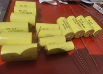
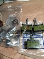
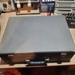
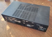
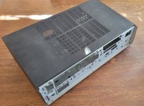
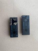
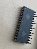
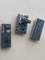
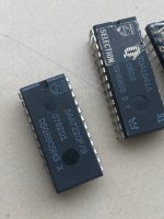
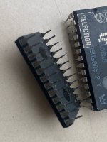
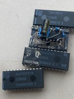
Been collecting vintage yamaha hifi for a while and have now quite some equipment, among other a C2 preamp and a T2 tuner, which feed an M4 power amp at the moment, all fully restored. A few weeks ago, a B2 power amp appeared on an auction site, listed as non-functional. The seller claimed that he had received it two years ago, tested it and then put it away until now as it did'nt work. Well, I couldn't resist the temptation and won the auction, although for some more than I wished for as it was listed as not working. The other day I picked it up, the cosmetic condition is very good, barely a mark on it. So on to the electronics, I opened it up, by the looks of it, it actually seems like it been unused for a quite a few years, some cobwebs and dust all over the inside. So I checked (not powered up) if there was any voltage left in the capacitors, no not even a few mV. Ok, unsolder the connections, unscrewed the heatsinks and remowed them from the chassis to access the VFET transistors. The moment of truth, are they okay or not? Testing the first one, it passes the ohm measurement and the diode test looks good, testing the next one.., the ohm measurement shows infinity and the diode test fails. When I had measured them all, there are two 2SK76, one per channel that measure as they should, the rest is toasted. Well, it was a calculated risk, had they been okay, it would have been a good deal, now it wasn't.

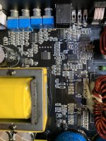
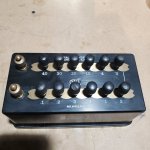
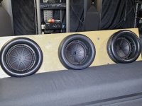
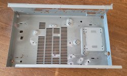
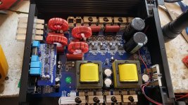
Since it is not likely that I can get hold of four matching pairs of VFETs, the question is what do I do now? Search patiently for VFETs, or use the chassis for a diy build? It's a good looking chassis with really nice vu meters, double transformers, and massive heat sinks. I think it will be possible to use the chassis for diy without making physical changes that cannot be restored. All circuit boards will be removed and keept safely if I would get hold of the VFETs, in which case I will rebuild the amp to original state.

Prerequisites:
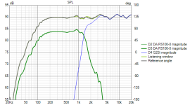
VAC from each transformer: 41V-0-41V, center tap, will give aprox +-54VDC, as I understand.
I will try to keep the meter board to drive the VU meters.
The two driver boards will be removed, dimensions 190x125 mm, giving space to new circuit boards.
Between the fins of the heat sinks there is 55x125 mm space for mounting power transistors (on each heat sink).

If going new diy amp, I would prefer Class A and have been looking at the F5M amplifier, although then it's not possible to use the existing transformers as the voltage would be much to high. If thinking class A/B, Honey Badger, the transformers could be used I think, saving some money.


If going the F5M route, I am thinking dual mono setup, two transformers 160VA, 2x18V, one for each channel.
F5M Core + two PSU kit. Will try to set bias at 1,4 A, or lower if the heatsinks gets to hot.

Yet another option appeared as I was looking through my stuff in the office, found a pair of Aleph 3 clone PCBs. What about this with IRF244 TO3 as outputs? Looks like these are avaiable at Digikey. In this case the TO3s would fit perfectly on the heat sink.


So my options:
1. Wait for four matched pairs of VFETS to be avaiable.
2. Go for F5M dual mono.
3. Go for Aleph 3, probably dual mono as well.


Any thoughts, opinions and advice are welcome.

Hans

P1010198.JPG

P1010203.JPG

P1010227.JPG

McIntosh manuals, sockets, pots

Time to clean things out before unable to do so 😂

1. Some McIntosh manuals and schematics.
2. Some 4-pin tube sockets (bought rom partsconnexion).
3. Three Alps (Japan) pots (100Kx2, 250Kx2, 250Kx2) the short one has a McIntosh logo.

Free to good home(s). I don't have paypal.

Reimburse postage by cash (should be less than US$20 in US),
please say so in this thread.

Ship from California, US.

Attachments

  • 2024-09-13_09-33-36.jpg
    2024-09-13_09-33-36.jpg
    107.5 KB · Views: 72
  • 2024-09-13_10-12-50.jpg
    2024-09-13_10-12-50.jpg
    389.7 KB · Views: 66

Micromega Duo CD3.1 schematic?

hi,

does anyone have a schematic for a micromega duo cd3.1?
the power transformer has died and i need to know the rating/voltages so i can get some kind of replacement.

it started to hum, then over time developed a slight buzz until it started really vibrate almost like a mobile on silent, then it suddenly stopped and then i noticed the player was off. tried the fuse, cable and then i opened up the cd player and could see that the top of the transformer has gone a brown colour like it was giving off loads of heat

how does this kind of thing happen? am i right to think that with age and heat that it has somehow 'de-laminated' itself which caused it to vibrate? the micromega has a circuit which is always powered up unless you unplug it, mabey thats why it died?

i have searched the web and found what i think are suitable replacements but without knowing the specs im stuck.

any info would be much appreciated
thanks

Barker & Williamson Audio Oscillator Model 200 troubleshooting

Hello diyAudio forum! I have a vintage Barker & Williamson Audio Oscillator model 200 that I am hoping to restore for this beginner's use on a test bench for learning more about and taking care of my own audio/guitar hobby tube amps . Brought it up on a variac and have connected to a tektronix 2465A oscilloscope to find irregular wave forms. Frequency controls appear to work, but there is pulsing variation in amplitude and shape as shown in the attached images. (I am also a newbie to using an oscilloscope.)
I am hoping knowledge base here can confirm that these symptoms point to either go/no-go decision to restore, and/or to an order of replacing likely causal components. I would replace the capacitors due to their age, but if the varying waveform and amplitude pulse points to other critical parts, I'd like to see if they are available and get a sense of the overall parts cost before investing up front in the caps. There are two (2) quad caps, and about 5 down below. I have not opened the frequency control box behind the big verneer dial!
There's a great video of a unit similar to mine working well, on youtube at: Login to view embedded media I have not been able to find a schematic, but I understand (from commenters on the above video) that it may be a licensed version of (the first!?) HP product. Any suggestions for this newbie is greatly appreciated! (This is my first "help" post here!)

Attachments

  • IMG_20240908_233501994_x2560_q7.jpg
    IMG_20240908_233501994_x2560_q7.jpg
    247.8 KB · Views: 42
  • IMG_20240907_215354274_x2560_q7.jpg
    IMG_20240907_215354274_x2560_q7.jpg
    259.4 KB · Views: 42
  • IMG_20240903_213147784_x2560_q7.jpg
    IMG_20240903_213147784_x2560_q7.jpg
    235.1 KB · Views: 43
  • IMG_20240903_212448450_x2560_q7.jpg
    IMG_20240903_212448450_x2560_q7.jpg
    225.6 KB · Views: 46

For Sale Thorens TD180 for parts

I have a Thorens TD180 table with Stanton cartridge I'm selling for parts. It is in good shape cosmetically. The strobe light lights up but the motor does not turn. Good for someone who knows how to repair or for parts. Comes with original Thorens power supply. I can email pics for anyone interested.

Asking $50 plus shipping costs in US only.

Thanks,
Jim D.

Attachments

  • Thorens pic 2.JPG
    Thorens pic 2.JPG
    462 KB · Views: 76

BEHRINGER Crossover help needed

I bought online one Behringer 2496 Le crossover many years back , now I want to use it in a 3 way active system :
(Tweeter :Scan Speak D3004/6600 ,Mid-woofer Scan Speak 18W8531G and Peerless HDS 8" as woofer in a separated box )
so the x-over points 2k0 Hz and 400 Hz @ 24 dB
The problem is I am not able to set up the crossover : I took it to most of the stores (in Vancouver ,Canada ) where I live but no
result . I am only 74 ,but my vision /my hands are not good enough to
pick up the soldering iron .I can send it via Canada Post /Fed Ex/UPS to your address ( Vancouver or Seattle only )

Thanks guys ,

A POSITIVE International transaction with VT4C

Just wanted to say THANK YOU Publicly to VT4C for an excellent transaction. Malaysia to the USA! I was a little hesitant buying from out of the country. you know you hear so many scam story's. but VT4C was Very accommodating. I asked that he take a photo of the item with a pieces of paper in the photo with his name and my name on it and he happily obliged! he shipped right away. packed the item VERY well. it was exactly as described. works great absolute A++++ transaction.

so THANK YOU VT4C for an excellent transaction!!!
  • Like
Reactions: gerrittube

PKAudio (Pida) Waveguides for Bliesma tweeters

From time to time I get request for the details of this waveguide so I created this thread to share the details, and to see the experiences and measurements from those who used this WG.

I can share STL/STEP files for 3D printers via email on request.

This WG was used with Bliesma T34B, all measurements are in the attachment. Measurements were taken in actual baffle of Ellips-A project.
https://pkaudio.webnode.cz/ellips-a/

Attachments

  • 6WG T34 40mm drawing.PDF
    6WG T34 40mm drawing.PDF
    30.8 KB · Views: 261
  • T34B WG dist.png
    T34B WG dist.png
    37.8 KB · Views: 344
  • T34B WG H 0-90.png
    T34B WG H 0-90.png
    78.5 KB · Views: 333
  • T34B WG imp.png
    T34B WG imp.png
    18.9 KB · Views: 336
  • T34B WG spinorama.png
    T34B WG spinorama.png
    17.8 KB · Views: 314
  • T34B WG waterfall.png
    T34B WG waterfall.png
    228.2 KB · Views: 331

BJT transistor matching requirements for various circuit blocks

Hello,

Just finished sweeping through more than 200 BJTs for my MC/MM phono preamp, measuring Hfe and Is indirectly through Vbe with diode function of a DVM. A bit of a PITA if you ask me, but you gotta do what you gotta do right? Or do we? Througout this endeavor I couldn't help but wondering, does any audio manufacturer goes through this trouble ? Still have 200 more of the BC549/BC556 to go through... 😡

Thank god for spreadsheets, I can sort the set by Hfe then Vbe or inversely. I also produced statitics from the 2SC2547D/2SA1085D set and right off the bat I can tell you I can't get Hfe matching for the two polarities out of 50 NPN and 100 PNP for the input transistors. I read here that this is normal for the epitaxial transistors.

Descriptive statistics also put forward the following properties:

1. Hfe is generally higher for NPN than PNP;
2. Hfe varies much more than Vbe regardless of polarity;
3. Hfe variance is much higher for NPN than PNP (300.2 vs 47.8)
4. Vbe variance is also higher for NPN than PNP (1.75 vs 0.81), but less variable than Hfe like mentioned in point 2;
5. In my sample, PNPs have Hfe range lower than specified in the datasheet... Bad batch, bad luck, fakes ????

That being said, I'm wondering what to aim for in different parts of the circuit (see below), keeping in mind that Hfe match may be impossible between polarities :
  • The parallel transistors of the input cascode need to be matched for Is; that is have the same collector current for a given Vbe for equal current sharing between them;
  • By which parameter to match the cascode's top transistors?
  • Hfe influences the device's dynamic emitter resistance (re), but when emitter degeneration resistors (Re) are present, Hfe matching is more relaxed. So do I need to place the closest matches where the re/Re ratio is highest, e.g. where the degeneration resistor has the least effect on total output impedance?
  • Do the CCS transistors need to be matched from one rail to the other? Matched for which parameter?
  • Do the current buffer transistors (discrete Darlington configuration) need to be matched, and if yes by which parameter, total Darlington combined gain from rail to rail? I feel these positions are less critical since gain will be high anyways...
  • By which parameter to match the legs of long-tailed pairs?
I know it's a lot of questions, I am really a newbie in all this and will appreciate any help!
- Joris
1707153139157.png

Power supply for (D) amps with high peak output

I lately got a 48V 350W SMPS from Chinese manufacturer MEISHILE. When I started it, my FM radio went crazy, even more than 5 meter away.
I installed some ferrite ring in the wire to the amp, which reduced this effect quite good and have no problems with it serving TPA3255 amps.
Anyway, a mixed feeling stayed, also the permanent running fan is audible.

So I decided to go for a MEANWELL product, which is considered good quality, maybe the best with China SMPS. Searching the options I noticed their new line with "N2" at the end of the model code, in my case the MEAN WELL LRS-600N2-48
It is different from the "normal" LRS supply, in having a 100% over current capability for 5 seconds. Usually such a huge peak helps to start up large inductive or capacitve loads. So it can give an impressive 1.2kW for a few seconds. This should fit well with an audio amp. It has a temperature switched fan, too.
I'm no expert on SMPS, so some ideas would be welcome. Also some might find this product line interesting for their own builds.
  • Like
Reactions: fb

Group delay in high order parallel

What causes a drastic reduction in group delay by adding a 100cm pipe to an existing 300cm pipe (with exits connected)?

(pink is both, white is the plain 300cm TL)

both pipes are at velocity max for that resonace where they join? Instead of the single pipe venting onto the driver’90degrees‘ out of phase at resonance ?

Attachments

  • IMG_0206.jpeg
    IMG_0206.jpeg
    38.6 KB · Views: 74
  • IMG_0208.jpeg
    IMG_0208.jpeg
    74.1 KB · Views: 69

Amplifier recommendations for DIY Speaker projects

Firstly I apologise if this is in the wrong area but didn't seem to really fit in the Amp section.
I love designing and building various speaker projects, im by no means an expert but I really enjoy it. I'm probably on my 10th project now. Most of my projects use built in amps and DACs but this is getting expensive. Instead I want my future projects to use crossovers in my speakers and the ability to run them from a single amplifier rather than build an amp into each project.
What amplifiers would people recommend for this? I have the following requirements making it a little bit tricky:

  1. I want to use the amplifier everyday as I tend to listen to music all the time whilst working
  2. I usually use a stereo system but I want to be able to power multiple setups like Stereo, 2.1, 4 and 5.1. I doubt I'll ever need 7.1
  3. Ideally would like to be able to adjust bass treble and of course volume
  4. Connection points for speaker cables don't matter too much as I tend to build my own cables for my speakers. Some use Speakon, others banana plugs etc. So this isn't a major factor.
  5. I would like some power behind it. My latest project is around 400watts
  6. Ideally bluetooth connection however not a major issue as can use a wire between my laptop and amp if need be
  7. Quality is important but I'll be honest I rarely can tell the difference between very expensive and decent amps.
    Thanks so much

look what showed up at my door

Guy down the street heard I was messing with this stuff and brought me some , I guess you would call them old toys . Starkit 9-99 , and a resistor block that is extremely accurate .. the meter had a bad resistor that I swapped out and seems to be working , seems a bit high but can't complain about the price ..

Attachments

  • 20240912_134631.jpg
    20240912_134631.jpg
    489.8 KB · Views: 97
  • 20240912_134716.jpg
    20240912_134716.jpg
    624.8 KB · Views: 96
  • 20240912_134740.jpg
    20240912_134740.jpg
    683.4 KB · Views: 94

NAD C 370 Power Stage Hum, then into Protection Mode

I purchased a NAD C 370 amp in pretty much immaculate condition a number of months ago. The amp has little use over the 20 or so years. It has worked perfectly for the past few months until last weekend where the sound became distorted. I switched off the amp and on again and it went into Protection Mode(Red light).

I unplugged the amp and put it aside. till I could test it properly.

Conditions-
Main Inputs L&R grounded, so no stray signals feeding the power section
Soft Clipping=Off
Bridging Mode=Off
8 Ohm B&W CM2 Book Shelves on Speakers A (I've also tested with McIntosh ML 1C Speakers as well

Behaviour
Switch on from cold, goes through the normal startup procedure
I get what seems like a 100hz hum/buzzing on both speakers
Switch off, then on again, goes through the startup procedure, then into Protection Mode
----
Leave it for a bit of time and it repeats the behaviour above, hum/buzzing then on second power on; into Protection Mode


I would lean towards the Zener Diodes degrading the Capacitors in the protection circuit if;
  • The Amp has had a lot of use over the years
  • The Amp is producing a 100Hz hum, and only going into Protection Mode after power cycling it

Has anyone experienced this type of behaviour?

Any advice would be appreciated.

TDA7520 equivalent ? the part is obsolete now

Hi !
I saw an interesting video on the repair of an old Lecson Stereo Plus integrated amplifier
This amplifier uses an obsolete TDA7520 integrated amplifier that drives a pair of power darlingtons, one per channel
The TDA is a dual driver
I found the pdf online and was surprised by the extreme simplicity of the application circuit proposed in the datasheet

1725956971202.png


Since the Lecson mentioned above seems to sound really good, I wonder why this solution is less used and especially if there are non-obsolete parts with the same characteristics as the TDA7520
I tried to search but I'm confused
thanks to everyone and have a nice day
gino

Please help me understand which T/S Parameters are important for my particular use

Hi!
So I am into home theater and building Tactile Response devices like Hovereze, HoverBack etc.
For example, here is a photo of my HoverBack setup only missing the thick vinyl to seal the tubes. Then a board is placed in front as my backrest to transfer all that tactile experience to my body.
The Hovereze is the same but is a platform on the floor so the sofa rests on top of it to get that impact. For example we get amazing wobble feeling effect on the Hovereze on frequencies like 1-4Hz or so and for the most part we use the bottom platform to over from 1hz to 20hz (some go higher like 40hz).
This is all a matter of preferences of course.
So what I would like to understand when comparing woofers is what matters most to handle those low frequencies, with the weight on top of them without going to smokeville.

Is it BL, FS, XMAX, QTs?

From my understanding I want high BL for motor strength.
Higher QTs like .500 or higher for this sort of sealed setup.
And of course higher XMAX.
The FS and frequency response I am not so sure how they relate as the ones we are using seem to hit single digits just fine for this use, even with FS and response that is not that low.
Thanks for any tips on this.

Attachments

  • 20240530_103200.jpg
    20240530_103200.jpg
    546.8 KB · Views: 55

Way too much 6505+ waterfall noise

Hi, I've been trying to pinpoint the source of a noise in a 6505+ head. These things are notorious for a bit of "extra hiss" on the lead channel, but this is a roar like a waterfall. With the gain up to 75% or so, and the master just barely turned past 2, it's so loud that it's unplayable. It's just as noisy with no instrument connected. I tried replacing all input tubes one at a time, and I noticed that upon pulling V1 out, the amp is nearly silent, even with the master all the way up. I tired running it with the input stage plate resistor disconnected, and it was a little quieter, but still too much. I noticed that the first gain stage of the lead channel has a 470K series grid resistor (stopper?). Replacing it with a new metal film didn't quiet anything down either. Then I replaced every series resistor in the entire front end (input and 1st and 2nd gain stages of both channels) with new metal films. No change in noise. I am presuming that the original amp was at least playable, so I am still looking for a fault somewhere before I start trying to modify something. I looked at all solder joints under a microscope and there is no evidence of cracking or cold joints. Any advice would be wonderfully appreciated!

TV-2/U bias pot

Hi guys I'm going through my newly purchased TV-2/U tube tester and have been experiencing problems with the Bias adjusting pot . was wondering if anyone has tried to replace this pot with another 10K , unlike the English wheel type pots on the Hickok 800 this pot does not have to be in sync with a graduated scale , I don't myself see any reason why any 10K pot that is precision enough and has correct wattage would not work . Brings me to my next question what do you believe would be the correct wattage for the 10K pot in this unit . was thinking of using a precision wire wound 10 turn 2 watt but not sure the wattage would be enough.. thanks for any help

10 years of XSim! Ty Bill!

Just noticed that @bwaslo released XSim just over 10 years ago. I can't express to bill how grateful I am for this tool. I've gotten endless enjoyment and education from using it to design a number of multi-way speakers. It's always just worked at everything I needed to work.

I hope others join me in expressing their gratitude to him for taking this work on.

Thanks again, Bill.

New Member Questions

Hello everyone! Brand new to the scene and excited to dive in. I've spent the last 2 months reading and re-reading Intro to Basic Electronics, Speaker Building 201 & The LDC 8th edition volumes I & II. I have also been learning Vituix CAD and playing with Xmachina. My next steps will be getting testing equipment. Any recommendations on a cost effective setup would be great! I have a good selection of old speakers from brands of varying quality that I plan on disassembling to use the drivers for experimentation. I have been playing with the half space responses of 2 MTM configurations. Both use the Dayton RS100-8 mid bass and I have experimented with the Morel CAT 308 dome and Aurum Cantus G2Si ribbon tweeters. After completing a few test builds with the drivers I currently have, these will most likely be my first real shot at a quality loudspeakers. I am currently using Cambridge Soundworks and Triad MTM speakers scattered around my house that I can use for reference. I understand that the half space responses are not indicative of what I will be working with in reality. I am going play with the simulated diffraction in Vituix now as practice but I have some concerns with my current designs that I could use some direction on. For both alignments I have good frequency response and the phase and group delay seem appropriate. My concern lies with the impedance. The first alignment using the G2Si tweeter shown below dips to 2.8 Ohm and hangs at 3 Ohm from 200-1200 Hz low point. The second alignment using Cat 308 in my next post runs 3 Ohm from basically 200-2000 Hz. The second alignment is more consistent and has far less circuitry but I would like to try and build both. In both configurations the problem seems to stem from the large parallel capacitor in the low pass section. However adjusting this drastically effects FR. I welcome any feedback on these designs! My questions are as follows.

Are these impedances going to cause problems for a lower end amplifier?

Is there an easy work around to raise the total impedance that wont affect efficiency to horribly?

How does the load phase affect the impedance? The peaks in phase correlate to higher impedance levels, when the impedance is at its lowest the phase is close to 0. This means it is mostly resistive correct? Does this present less of an issue for the amp?

How does the acoustic phase look? Configuration 1 is 90 degrees out of phase in the low pass stop band. Is this ok?

If I invert the tweeter I get a 6 dB drop at the crossover. Is that steep enough?

Does any of this matter as it uses half space responses not real world measurements?

Thank you all in advance! So glad there is a place where I can have access to the wealth of knowledge you all have to offer. I attached the Vituix project file as well as pictures of all the relevant graphs. Alignment 1 is crossover variant 1. and 2 is 2

Attachments

  • TEST 2  XO-schematic.png
    TEST 2 XO-schematic.png
    6.7 KB · Views: 57
  • TEST 2 GD+Phase.png
    TEST 2 GD+Phase.png
    8.9 KB · Views: 57
  • TEST 2 Impedance.png
    TEST 2 Impedance.png
    7 KB · Views: 55
  • TEST 2 INVERTED SPL.png
    TEST 2 INVERTED SPL.png
    10 KB · Views: 51
  • TEST 2 SPL.png
    TEST 2 SPL.png
    12.3 KB · Views: 59

Build log: The Stir Fry - A throw together for the basement

G'day Guys,

I hereby start my build log of what will certainly be one of the ugliest projects around.

The old fridge clear out special (often quite tasty I might add): old experiments and obsolete projects thrown into the wok for a yummy creation suitable for listening in the basement while I fabricate more attractive things.

The goal of this project is to make a 50w per channel stereo amplifier with bluetooth for the least possible cost, time and effort.

First up may I introduce the chassis:
A salvaged chassis from a faulty old Yamaha RX-385 I got for free some time back:
Here's a photo of the original unit I found on google.
1723456824732.jpeg
And after disassembly many years back and a little bit of hacking it now looks something like this:
20240811_150630.jpg
20240811_150807.jpg
20240811_150757.jpg
20240811_150640.jpg
20240811_150637.jpg

It has some useful features:
1) It has a metal front panel unlike most salvaged av receiver chassis which saves me some bother fabricating one.
2) The back panel doesnt have too much crap on it so I can work around what is there rather than fabricate a new one.
3) It just happens to have mounting holes in place for the power transformer I found in my stash for the project.
4) It has some half decent venting in place for cooling.
5) Not too small, I can squeeze in what I need to.
6) It was free, a bit of drilling and it should be ready to go.

The budget for this project is $0 so I will be using what I can find in my stash

I will take the opportunity to experiment with using household paints on steel. Also to see if I can paint over this horrible thick black vinyl like stuff that comes on these things.
Just you wait and see the colour I plan to paint this thing. Hint:
I have a 4L bucket of an appropriate colour for painting a 3 year olds furniture.

Next up I will introduce some of the other ingredients in the stir fry.

Attachments

  • 1723456707491.jpeg
    1723456707491.jpeg
    35.6 KB · Views: 85
  • 20240811_150637.jpg
    20240811_150637.jpg
    373.2 KB · Views: 80
  • 20240811_150640.jpg
    20240811_150640.jpg
    512.3 KB · Views: 74
  • 20240811_150757.jpg
    20240811_150757.jpg
    550.3 KB · Views: 68
  • 20240811_150807.jpg
    20240811_150807.jpg
    561.2 KB · Views: 85

PP First stage, triode or pentode?

Hello!
I have a question, what would be the preferred option for the first stage in a typical 6L6/EL34/KT88 push pull amp (with gNF) using a voltage amplification stage, LTP and output tubes? Triode or pentode? Advantages/disadvantages? I tend to favour triodes, but there are plenty of successful amplifiers using pentodes for the first stage, hence the question.
Thank you!
Jose
1726060053948.png

Open baffle with Philips AD 3800M and AD3460AM

i am just trying to make an ob speaker for my hiohm philips otl amp with EL 86.
in addition to the sprakers i habe two 2x12 active subwoovers, so bass is no problem.
Cause both speakers are fullrange i wonder if i should let run them just in parallel. The 3460 has a high tone conus inside. The 3800 not. The AD3460 AM runs fine alone as well, butin the lower midvrange the AD3800 M has more volume.
Does anyone know if it would be better to use just one speaker, e.g. an AD3800 AM which has a high conus as well. Is its performance in the highs significantly better than the AD3800M without the additional little conus?

Lot Philips TDA1541 S1 and some others

Sold as a lot only:
-TDA1541 S1 Q-Selection (Pulled from a Marantz CD85)
-TDA 1541 A (Used, but not pulled)
-SAA7220P/B
-SAA7220 Nos module

Some are used an pulled. Best to solder them in a new PCB.

Asking: E. 200,- incl. shipping?

Paypal. And EU ans USA only.

Attachments

  • IMG_1091.jpg
    IMG_1091.jpg
    379.2 KB · Views: 146
  • IMG_1092.jpg
    IMG_1092.jpg
    313.8 KB · Views: 113
  • IMG_1093.jpg
    IMG_1093.jpg
    379.5 KB · Views: 105
  • IMG_1094.jpg
    IMG_1094.jpg
    397 KB · Views: 113
  • IMG_1095.jpg
    IMG_1095.jpg
    405.9 KB · Views: 106
  • IMG_1096.jpg
    IMG_1096.jpg
    387 KB · Views: 102
  • IMG_1097.jpg
    IMG_1097.jpg
    437.8 KB · Views: 118

Crossover Group Delay Audibility Testing - please take part!

MY GROUP DELAY AUDIBILITY TESTING IS NOW LIVE
Please use the link in the description, below.

I have launched a suite of online tests where you can see if you can distinguish between various levels of group delay that have been added to several different signals (both synthetic and music types).

These tests are quite difficult, even with the synthetic signals. I have added group delay in levels from inaudible to audible, based on the published literature.

PLEASE ENCOURAGE OTHERS TO ALSO TAKE THESE TESTS.
WHY?
ANSWER: The audibility level for group delay in loudspeakers is an important parameter that puts strict limitations on crossover filter design. Once I have a sufficient number of respondents I will analyze and share the data and full details on the adulterations used to generate the test signals. This information will hopefully be useful to the loudspeaker design community at large.

GROUP DELAY TESTING MAIN PAGE:
http://audio.claub.net/GD_testing/GD_Testing_Main_Page.htm

For Sale Clearout: Pass, Dynavector, EMT, Vinie Rossi....

Hi,

Need some space and cash.
OPEN TO OFFER
NO TRADE please, only item I need is a lovely head shell for my Shick. Something fancy please 😎

EMT TSD 15:rebuilt by AnaMightySound, new coils. Specs available, boron cantilever. Few hours on it since rebuilt: Asking 750 EUR

DYNAVECTOR DV-XX2MKII : rare opportunity to own a true high-end cart for cheap. Need a new stylus, Soundsmith boron is the usual suspect (450$). Asking 500 EUR

Audio-Technica AT-670T:
Very well regarded SUT, it can manage a lot of carts with his impedance settings 3,20,40.
Denon, EMT works well with. Asking 300 EUR

PASS ACA: Asking 350 EUR , very clean built. Comes with 2 SMPS

Vinnie Rossi: Sublime 24VDC power supply from master Vinnie Rossi. Asking 300 EUR

SBooster: 19 and 5 VDC Asking 200 EUR each

Clearaudio Stability Headshell: very nice and clever head shell, almost new. Asking 175 EUR (picture will come)


Pictures

Cambridge A500 - turns on, no sound, suspected Darlingtons dead

Hi all,
First post here and thank you in advance for the wealth of knowledge that I have been able to gain thus far.

I have a Cambridge A500 that no longer produces sound. The green Power LED comes on as well as the two red LEDs inside the unit. I expect that the problem here is (at least) the very obviously dead SAP15 P0 Darlington. I understand that sourcing a replacement set can be challenging and there may be downstream resistors that may also have been taken out.

So 2 questions if I may:
1) Is this worth repairing and if so, are these parts readily available?
2) This is just an assumption about the Sanken SAP but is there anything else I could check to verify this?

Thanks!


IMG_0152.JPG


IMG_0151.JPG

For Sale Dual TPS7A4700 low noise PSU - Rudi Ratlos

For sale is a bunch of dual TPS7A4700 PSU PCBs. Designed by Rudi_ratlos, originally for some of his amp designs like Symasym or FC-100 frontends. Very versatile in choosing output voltage by jumper. Can be used as dual mono or in bridged mode. Fits everything needed (X-former / Rectification / Fuse). Currently have 14 PCBs at hand. Relatively low cost to build at around 30€.

Asking 8€ / PCB + shipping + PP

IMG_6977.jpeg

Judgment call on the effect of a bandpass filter

I'm designing something for reproducing the recorded sound of a church bell over a PA system. The bell has a dominant fundamental frequency of 700Hz with all the complex harmonics and resonances of a brass bell.

To reduce extraneous noises, I'm thinking of passing the signal through a simple passive bandpass RC filter - a second-order high-pass and a first order low pass. A tentative design of the filter produces these results: Relative to a broad mid-range centered around ~3.3 kHz, the response is down -1.8dB at 700 Hz, -1.5dB at 15 kHz, and -21dB at 100Hz. Phase is about +50º at 700 Hz and -30º t 15 kHz.

The target audience is a collection of 'ordinary' people, that is, not audio enthusiasts with trained ears. Do you think they will easily notice the difference between the filtered and unfiltered sounds? (It doesn't really matter if they do notice but well, I'd like to have an idea).

Upgrade of Linn LP12 Lingo 2 PSU to Zeus

The ancient Lingo 2 for my LP12 turntable was not providing proper voltages and the 33 and 45 RPM speeds were slightly off. Updating to a Lingo 4, Valhalla or a Linn Radikal would have been extremely expensive, and options in the U.S. were limited and would have involved shipping the whole works to someone. I am still uncertain if a Valhalla PSU or Radikal would have been possible, but the cost was prohibitive and unacceptable. After much research, I found the Zeus motor speed controller from Valhalla Electronics and decided to give it a try. This is a brief report of my experience in doing so.

Steve at Valhalla was prompt and helpful with pre-sales technical support, assuring me that the Zeus PSU would work as a Lingo 2 upgrade, and was designed for customer installation (he was right!). The instructions were very thorough and available to me as soon as I ordered so I had everything I needed ready to go when the Zeus arrived (like a plug for the oil reservoir in the LP12 so it could be inverted, along with an AC power cord). Removing the Lingo internals and installing the Zeus was easy and went very quickly. It turns out that while the old Lingo accepted a U.S. power input, it communicated to the turntable motor in "U.K. mode." The setup application that comes with the Zeus gives great flexibility, and made it easy to deal with this hybrid setup and put the U.K. values into the Zeus EEPROM configuration.

The turntable is now spinning at exactly 33.33 and 45.00 and holding those speeds very precisely. This is done with a feedback loop, monitoring the speed with an optical sensor and making adjustments if needed every 50 milliseconds. Since I went with the internal Zeus setup, I have the added bonus of now having one less box cluttering the countertop next to the LP12. This upgrade gets my highest recommendation!!

By the way, if you curious what Steve looks like, you just have to look up “Customer Service” in the dictionary — his picture is shown right there next to the definition. 😉

-Jon
Projects by fanatics, for fanatics
Get answers and advice for everyone wanting to learn the art of audio.
Join the Community
507,774
Members
7,887,959
Messages

Filter

Forum Statistics

Threads
406,208
Messages
7,887,959
Members
507,774
Latest member
pete2000