NAD C356Bee shunt regulator blew up, help!

Hi,

i Upgraded my NAD C352 with a 356Bee some days ago. The Amp worked absolutely fine and the sound improvement was even a bit more than i had expected.

As i opened it up to clean the inside from dust and get a short overview of the board i immediately saw blewed up a shunt regulator sitting there.
20240627_205520.jpg


The Regulator ia an AZ431BZ-BE

Screenshot_20240702_215203_Gallery.jpg


Unfortunetly that regulator isnt existing anymore.

The only ones i could find were

AZ431BZ-ATRE1
AZ431AZ-ATRE1
Screenshot_20240702_215223_Gallery.jpg

As i understood, the AZ or BZ Versions differ in the entrance Voltage tolerance of 0.4 -0.8%

Also the others go from 2,5 up to 36v instead of the Original BZ-BE 2,5 to 18v

So my question is one of these, the right regulator to exchange the blown up one?

If i just can get the 2,5 to 36v Versions is an exchange enough or do i have to regulate something after because of the larger range?

Thanks for any help!!

cheers
Screenshot_20240702_223254_OneDrive.jpg


Screenshot_20240702_223617_OneDrive.jpg

Magnum K crossover L-pads resurrected - Happy bunny

I was given some very rough Goodmans Magnum K speakers when I went to collect a Goldring 88 deck.

The drivers worked but the sound was poor. Removed the stuck-on backs with the continuous-pull method. All the capacitors measured correctly at 10 and 4 uF, double checked by running 50Hz through them and measuring current. I replaced the 4 uFs with 2 * 2.2 Polyesters anyway. All four L-pad potentiometers were unserviceable.

The failure mode was high resistance between the moving wipers and the fixed centre terminals. The HF pots were easy to open but I had to get medieval with the MF ones. After all, the pots are otherwise scrap. Cleaning made no difference. Using some very flexible instrument wire I soldered to the wiper and to the terminal. 4 times. Very easy to do.

Result was surprising. The speakers go very low - I was hearing bass notes on the club-dance tracks I never heard in the clubs! This from 35 year-old metal cassettes.

They really are competent speakers for a mid 1960s design. If I want accuracy and realism use the 'statics. For trouser flapping use the Goodmans.

Incidentally the crossovers are similar to but not the same as the cct diagrams I've seen on this forum and others. The signals from the crossover filters go to the centre of the pots. Either the mid or the high - can't remember which, has a 15 Ohm load resistor to ground at one end of the pot's track and the driver at the other end of the pot's track. So you select between sending the signal to the driver or to the load or to a combination thereof. If anyone wants the details I'll open them u[p again.

T-Line Design Help/Review

Hello,

Hope you had a good weekend!.

Looking for guidance and help regarding a t-line design for car audio purposes only.

Driver
Soundqubed HDS 2.208
https://soundqubed.com/8--hds-2.2-series-subwoofer/
called them to confirm RE
Screenshot 2024-10-21 112947.png


I am planning to have two of these. They are Dual Voice Coil 4ohm and will be wired in parallel for a total of 1ohm. Hence I have selected ND as 2P and the same for BL (blp) signifying voice coils wired in parallel. Eg was input as 1000W and 1ohm hence 31.62. Followed the old school guide of line length (196cm) calculated from Fs and line area from cone area (412 in this case as I have 2 subs).

Screenshot 2024-10-21 113004.png


Frequency Response

Screenshot 2024-10-21 113145.png

Next I checked the displacement. It was exceeding max of 13mm but a subsonic or high pass filter at 30hz should take care of that.

Screenshot 2024-10-21 123405.png

Screenshot 2024-10-21 123426.png


I also checked group delay and mouth velocity. From what I have read about ported box, group delay of around 40 is fine. As for mouth velocity, they say that needs to be around 30 but this 45 is at 1000w input. Not sure if at that power I will actually hear the port noise.

Screenshot 2024-10-21 113942.png
Screenshot 2024-10-21 115413.png


Questions I have

  1. Assuming this is based on old school quarter wave theory, Have I done or made any wrong assumptions till now.
  2. Since my goal is to put the t-line in the trunk of a car, do I really need to care about the sharp drop at 120hz? Most car audio setups will set a low pass filter at 100-120hz if not lower at around 80hz. I have read and simulated that to fix this we can place the subs roughly at around 1/3 down the line. If placing 1/3 down the line is not possible, then even having subs and vent diagonally opposite or as far away from each as possible will help because the "Path" comes into picture. Hopefully my understanding of "Path" is correct.
  3. I know this is the old school design and can be improved, but how do I go about it. In my forum introduction thread Dave aka @planet10 mentioned "Sd has little to nothing to do the line design. Vas is what is pertinent". Can someone please explain this to me.
  4. The peak at around 40hz I believe can be fixed by some stuffing either in first 1/3 of line or last 1/3.
  5. Do I need to worry about Group Delay and Mouth Velocity. If so, how do I reduce those.
  6. All sims assume that the box is a straight line, which it might not be and in this case it won't be. What affect does line folding have.
  7. If these drivers are not suited for a t-line, then please suggest some others or what to look for when choosing drivers for a t-line.

Questions You might have for me

  1. What are the goals? An SQL system
  2. Why duals 8's? 8-9 years back I had a t-line in my car but it was not designed or built by me, I knew nothing about t-lines. I lost the car and system in a crash. I want to put subs in my car again and there was nothing I didn't like about it. It could get loud if I wanted it to, and if I turned down the bass knob it would not bother the neighbors 😉. I am trying to recreate the same setup. The exterior dimensions of the box were around 30" wide x 22" deep and 11.5" high, .075" birch plywood. I am limited by height if 11.5 for putting the box in the trunk. Once in the trunk I should be able to add a baffle (to raise the total height some more) in case I decide to replace the dual 8's with a single 12. I believe max side I can go is 34" and depth be 24". If depth is 24 then subs will have to be mounted along the depth face (which could be good as they would be closer to 1/3 down the line).

Please let me know in case you have any more questions for me.

Thanks a lot for reading and hope you have a good day ahead.

Edit
Attaching Hornresp export for dualhds208

Attachments

  • Screenshot 2024-10-21 113314.png
    Screenshot 2024-10-21 113314.png
    13.4 KB · Views: 37
  • 1729527216569.png
    1729527216569.png
    25.8 KB · Views: 35
  • dualhds208.txt
    dualhds208.txt
    2.7 KB · Views: 25

UA 175B Limiting Amplifier - Transformers Identification

Hi,

I'm trying to identify the UTC transformers used in the Universal Audio 175B.
So far I've come across this references but can't find more info on the T3 UTC PA-6003, anyone can help ?

T1 : UTC 0-1 : Low Z to grid (Pri : 50, 200/250, 500/600 Ohms // Sec : 50 KOhms)
T2 : UTC A-19 : Plate to PP grids (Pri : 15 kOhms // Sec : 80 kOhms (split) )
T3 : UTC PA-6003 : ( Custom winded by UTC for UA's 17(5/6/7) Limiting Amps ? )

Thanks for your help !


PS: I'm looking at UTC 1963 catalog


UA17567Litcomp_Page_15.jpg


2.-Universal-Audio-175B-Rear_3000x800.jpg


3.-Universal-Audio-175B-Left_3000x1800.jpg

5.-Universal-Audio-175B-Top_3000x1600.jpg

7.-Universal-Audio-175B-Top-Internals_3000x2100.jpg
6.-Universal-Audio-175B-Bottom_3000x1600.jpg
8.-Universal-Audio-175B-Tube-Compressor-Limiter-Analog-Vintage-Rare_3000x2100.jpg
universal-audio-175b-rear.webp
9.-Universal-Audio-175B-Front-Internals_3000x1200.jpg

1729605559417.webp
1729605450227.webp

utc_transformer_catalog_1963_Page_06.jpg
utc_transformer_catalog_1963_Page_07.jpg
utc_transformer_catalog_1963_Page_05.jpg
utc_transformer_catalog_1963_Page_18.jpg
1729605269398.png

Attachments

  • 9.-Universal-Audio-175B-Front-Internals_3000x1200.jpg
    9.-Universal-Audio-175B-Front-Internals_3000x1200.jpg
    293.9 KB · Views: 35
  • universal-audio-175b-inside.webp
    universal-audio-175b-inside.webp
    31.3 KB · Views: 42

Research project, active speaker design and implementation

Hello all,

I wanted to introduce myself and an ongoing project I have, well really a whole series of projects. As a way to learn a bunch of techniques related to audio engineering, purely as a hobby to stop brain rot, I have a pair of active speakers from the 1980’s, Meridian M30, which I am hoping to have a long-term experiment with. Fortunately I have the schematics for the crossovers and amps.

As a summary, highlights of these speakers are:
  • KEF T33, 180DC15 drive unit pair, both 4ohm
  • Active crossover based on many 5532s with some interesting signal shaping
  • 2x70W power amps based on BD139/140, MJ15003/4 output pairs
  • Regulated 15v power supply using 7815/7915
So far I have done the following “basic hygiene” tasks
  • Replaced all the electrolytic caps (which removed a punishing crack on power up)
  • Replaced the ferrofluid in the tweeters
  • Captured the schematics into LTspice (at least 98% of it)
  • Taken some acoustic measurements with REW/UMIK-1 that seemed to correlate with the crossover design, including a whopping dip designed into the presence region
My aim in this project is to understand by practical activity the effect of changes in electronic/mechanical design, hopefully to produce an “improved” version by the end. Although not a “cost no object” project, I am fully expecting it to become a bit of a money pit over time! At some point this will include getting a 'scope but that's a fairly major jump.

So, I have a few questions I wanted to raise.
  • I was planning to document the project as I went. In terms of diyAudio etiquette, should I put this all in a single thread, updating the first entry as I go, or should it go in a series of threads?
  • As it includes parts of line level, power amp and speaker (drives, cabinet), should I raise questions for each in their own forum areas?
  • The schematics are reasonably easy to obtain online in PDF form, but I think I will only provide snippets from the full diagram publicly. Does this fit with the forum’s IP/copyright approach
  • If you were crazy enough to try this yourself, in what order would you consider review/upgrade? Following a source-first approach my thoughts would be to look at power supply, then crossover, then power amp.
  • Is the T33 tweeter a bit long in the tooth nowadays and could be improved?
  • Are there more modern output devices that could produce interesting changes or are there other places to start.
  • I replaced the electrolytic caps and the remainder are mostly polypropylene and a couple of tantalum ones. Would these normally be replaced too? Any other components that would tend to age and should be replaced as a matter of course?
Thanks for any support you can give!

Ian

Metaxas CP-1 - Impossible repair? Crackling & Popping on one channel.

Hello,
i got my hands on a CP-1 from MAS Metaxas.
never heard of it? me neither,
34Qzy63.jpg

zl7rBBt.jpg


its so rare, you wont even find it on the internet, except in 2 (now 4..5) places.
seems to be from the 80s, probably 86.. 87 or so.
in their "how it all began story" pdf mentioned on page 7 http://www.metaxas.com/HIFI_2015.pdf
on some site mentioning it in "DAS OHR" magazine and the 2 or 3 posts i made.

i found a picture of a later revision, still CP-1 but industrially made PCB instead of self-etched. in low res, due to original got deleted and using google image cache.
ncl5GQe.jpg


it has a technical problem i cant seem to fix, atleast not easily.
one channel loudly pops and crackles when its cold, after warming up it goes away.

im listening to it since an hour now, and havent heard a single crack / noise anymore.


the popping is so loud, it basically swings almost from rail to rail. and then it starts to create noise after settling. hooking it up directly to a high power amp will likely damage it or the speakers attached.


enmV6x4.jpg

gRkTohq.jpeg

4bKICGN.jpg


its not mechanical issue, i tapped and hammered on it, but couldnt reproduce it, it comes and goes on its own.


i replaced all capacitors with new panasonic (FC & FC-A) ones and a x-class foil cap in the supply and renewed the thermal compound, but the issue still persist.
(attached pictures show stats before replacing components.)


i narrowed it down to be one of the potted Gain cells which control the output gain. before that, everything seems to work even the phono stage.

The signal before that is clean and the powersupply doesnt glitch when it happens. so it must come from one of the gain cells.


i confirmed that by swapping left and right, and the issues moved with it.
(its the one with the ripped off sticker in the attached pictures)

gFdFJCl.jpeg


The potting doesnt look like epoxy, more like very hard tar.. bakelite? shellac? cracked corners look like glass / obsidian, its very hard,

i have no clue.
i tried melting it with a soldering iron, well it stinks badly but didnt get soft.


GjTbMBU.jpeg


The faulty cell is 2°C hotter after a hour of listening, and as i mentioned, at this temperature the crackling and popping is gone.
(ignore the hotspot top left, its the resistors for the front LED; they are both dropping 46V no idea why one is hotter, powersupply is perfectly 23.8V -24.1V on both channels.)

i suspect it to be a discrete opamp to be inside, but i havent got a xray machine (yet 😛)

it has 5 connections, +-24V, signal in and out and capacitor feedback of some sort. (2 tantalums in series, in paralell with a foil cap)


also since theres no info about it anywhere, its very unlikely to find a schematic.


anyone got a idea what to do?
can anyone can tell me something about this rare unit?


rebuilding both cells either descrete or with opamps is the last resort.

its definately not something to throw away.


i also contacted the inventor, kostas metaxas if he can tell me more about this unit but havent heard from him yet.

Attachments

  • IMG_20200812_094825.jpg
    IMG_20200812_094825.jpg
    704 KB · Views: 245
  • IMG_20200808_170040.jpg
    IMG_20200808_170040.jpg
    713.2 KB · Views: 229
  • IMG_20200808_170053.jpg
    IMG_20200808_170053.jpg
    571 KB · Views: 215
  • IMG_20200808_170138.jpg
    IMG_20200808_170138.jpg
    456 KB · Views: 206
  • IMG_20200808_170156.jpg
    IMG_20200808_170156.jpg
    615.1 KB · Views: 217
  • IMG_20200812_010040.jpg
    IMG_20200812_010040.jpg
    533.5 KB · Views: 230
  • IMG_20200812_010122.jpg
    IMG_20200812_010122.jpg
    434.3 KB · Views: 210
  • IMG_20200812_092703.jpg
    IMG_20200812_092703.jpg
    367 KB · Views: 214

Help! Transistors replacement AudioAnalyse A9 power amplifier

Hello Experts, I have a question regarding the replacement of transistors in my AudioAnalyse A9 amplifier (Pure Class A, 50WPC). This amp delivers excellent sound quality, which I really enjoy (sweet, calm, with a wide soundstage). Unfortunately, two MJ15015 transistors have shorted, and after reviewing the schematic, my technician friend raised a few concerns and suggestions. I would appreciate your expert opinion on the following:
  1. Why are the same transistors (MJ15015/MJ15016) used both in the output and driver stages?
  2. Can we replace the MJ15015/MJ15016 transistors with MJ21193/MJ21194 across the board?
  3. Considering the different HFE values (20 vs. 75) and Ft ratings (1MHz vs. 4MHz), would this be an upgrade or potentially cause issues?
  4. If MJ21193/MJ21194 can be used in the output stage, should the driver stage transistors also be replaced?
  5. Or should we stay with the original value transistors?
Your guidance would be greatly appreciated. Thank you!

(Schematic attached)

Attachments

  • IMG_8177.JPG
    IMG_8177.JPG
    169.4 KB · Views: 91

Bewitch KT88

Hi,

I'm new to diy audio and have no experience in modifying amps. Few months ago I bought a Bewitch KT88 on ebay and so far I like it a lot, one of the reasons I bought the Bewitch was the positive review on the Lampizator website (Bewitch).
He also made a recommendation on some mods. I'm planning to follow his mods, but recently I heard from some people that the Lampizator mods might not be as good as he claims.
Can somebody give me some information about this mod?

http://lampizator.eu/AMPLIFIERS/CHINA/bewitch 6550/IMG_5577.jpg

Hello It's Me

After months of getting information of this place, i finally decided, to join and become part of the community.
Being a musician and teacher of technical crafts, one doesn't have to think far to try to build the stuff you need by yourself. Starting with simple audio cables, passive audio splitters, adapters and so on, I got my hands into building more and more complex projects, including power amplifiers and parts of my PA. Looking forward to share some projects and learn from the more expierienced around here.

cheers

Discrete OPAMP based on balanced VAS from HITACHI app note with Two Pole Compensation OLG 80dB at 20kHz

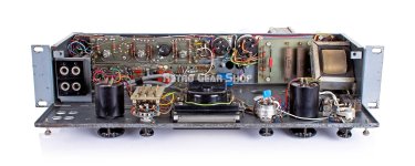
Hitachi's advancements in amplifier design, particularly through the use of power MOSFETs, have significantly impacted the audio industry. Their balanced voltage amplification stage design, outlined in their application note, transformed the way amplifiers were built, enhancing performance, efficiency, and sound quality.

hitachi-an-front-page.PNG

In the early days, bipolar transistors were the dominant components in amplifier circuits. They were valued for their high gain and efficiency, but as the demand for higher fidelity in audio systems grew, the limitations of bipolar transistors became more apparent. They required higher driving power, were prone to distortion, and exhibited significant phase issues at higher frequencies. Recognizing these challenges, Hitachi was one of the first companies to explore the potential of MOSFETs (Metal-Oxide-Semiconductor Field-Effect Transistors) for high-output amplifier designs.

Hitachi engineers initially worked with small signal MOSFETs used in TV tuners and similar high-frequency applications. Through years of refinement, they adapted this technology to create high-power MOSFETs, which offered significant improvements over traditional bipolar transistors. This led to the development of amplifier circuits that took full advantage of MOSFET characteristics, particularly through the balanced voltage amplification stage.

According to the application note, power MOSFETs offer several distinct advantages over bipolar transistors, making them ideal for high-performance audio amplifiers. Power MOSFETs are voltage-controlled devices, which means they require significantly less driving power compared to bipolar transistors. Unlike bipolar transistors, MOSFETs are free from current concentration, making them far more resistant to damage from electrical stress or thermal runaway. The absence of carrier storage effect in MOSFETs enables a high switching speed and excellent frequency response.

While power MOSFETs brought clear advantages, their inherent distortion (approximately 20 dB higher than bipolar transistors) required Hitachi engineers to rethink the design of the voltage amplification stage. To mitigate this distortion, they developed a balanced voltage amplification stage, which allowed them to increase the open-loop gain and apply larger amounts of negative feedback—key to reducing distortion without compromising bandwidth.

hitachi-sch-50w-v2.PNG

The balanced voltage amplification stage works by taking signals from both the inverting and non-inverting outputs of the long tail pair input stage, a critical design decision that maximizes the amplifier’s ability to reject common-mode noise and increase overall gain. By amplifying both signal paths symmetrically, Hitachi’s engineers were able to apply larger amounts of negative feedback over a wide frequency range, effectively reducing distortion.

In bipolar transistor designs, a Darlington connection is often used to increase bandwidth. However, this two-stage emitter follower configuration introduces significant phase distortion, which complicates the application of negative feedback. To compensate for this, phase compensation circuits are required, which can further degrade performance by sacrificing gain and limiting the overall frequency response.

Power MOSFETs, on the other hand, offer a significant advantage. With a single MOSFET source follower, large amounts of negative feedback can be applied over a broad frequency range without the same phase issues. This allows for greater stability and lower distortion, particularly at high frequencies. Furthermore, the driver stage of a MOSFET does not require a conventional class B driver, which reduces the number of components and simplifies the amplifier design.

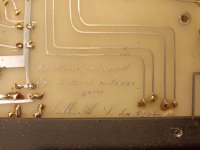
From the application note on design of voltage amplifier stage:
"A power MOS FET can be used with a low driving power. Fundamentally, only the power for charging and discharging the gate-to-source capacitance is needed to the output stage, so that no class B driver stage is required. The driving power varies with input frequency. At 100 W output and 10 kHz frequency it would be about 10 mW. Therefore, an output stage power MOS FET can be driven directly from a class A predriver (voltage amplifier stage) used in a bipolar transistor amplifier. By eliminating the class B driver, the number of components can be reduced, and impairing the amplifier's performance caused by the driver itself can be avoided. Further, the number of poles for transfer function (open loop gain vs. frequency characteristics) decrease, and the stagger can easily be increased. Consequently, the stability against oscillation is improved. Transistors for the voltage amplifier stage are required to have a high voltage durability, low Cob and high fT. Here the 2SD756A/2SB716A developed especially for power MOS FETs are used. With the NPN differential amplifier and PNP constant current load, high gain and low distortion characteristics were obtained. The class A stage bias current is set as 10 mA. When bias current is lacking, sufficient power to drive a power MOS FET at high frequency cannot be supplied, and distortion would worsen. The drain current temperature coefficient of a power MOS FET undergoes a reversal of polarity at around ID = 100 mA and temperature compensation in the large current region will be unnecessary. Hence, the bias circuit for a power MOS FET is vastly simplified because only one semifixed resistor (1 kOhm) for setting idling current will suffice. For the input stage, a stable differential amplifier circuit was formed by using the high-voltage, low-noise transistor 2SA872, which is known for its high performance in improving the S/N ratio. Bias current is set as 0.5 mA."

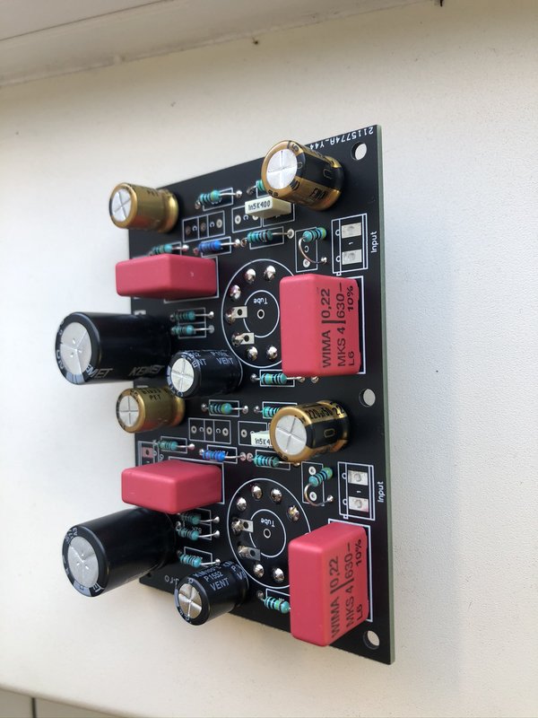
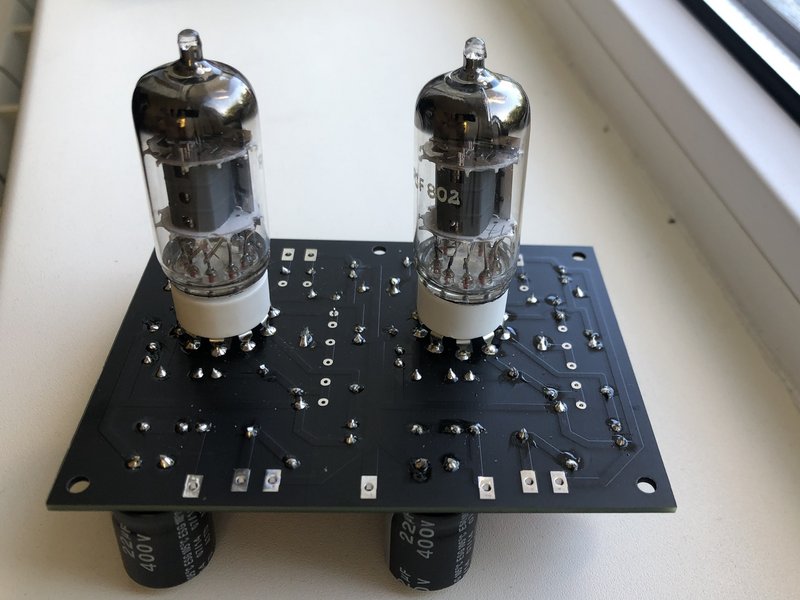
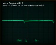
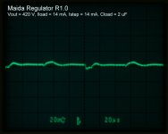
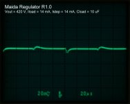
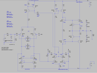
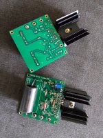
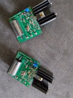
Inspired by Hitachi’s innovations, I have decided to create an op-amp design based on the differential voltage amplification stage. This design leverages the balanced approach to drive the output stage of the op-amp, optimized for small signal processing. Since typical op-amp loads are as low as 600 ohms, compared to the 4-ohm loads found in power amplifiers, the current-driving requirements are much lower.
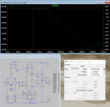
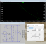
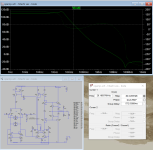
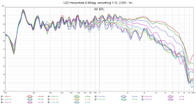
Opamp specs:
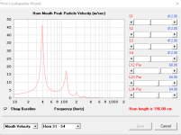
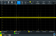
THD (G=+1, 600R, Vin=1.41Vrms, 1kHz): 0.000007% or -143dB
THD (G=+1, 600R, Vin=8.5Vrms, 1kHz): 0.000054% or -125dB
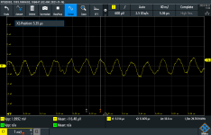
BW (G=1): 10MHz
Noise: 1.95 nV/Hz1/2
Voffset: 0.02mA
AOL (100Hz): 110dB
AOL (20kHz): 80dB

Attached you can find Hitachi app note and opamp design in LTSpice simulation.

Attachments

  • Like
Reactions: 70145 and Mooly

DeForest DL5

IMG_0112.jpeg
Hello everyone!

Today I received 2 DeForest DL5 tubes.

I swapped out a Cunningham CX301-A Harrison Plant, long glass bulb in my amp for the DL5 (120H choke loaded , 120V anode ,ballery biased with -8V on the grid.)

Sounds wonderful! Better than the 01A in many respects. I will go back to the O1A and do more comparisons to see if I can decide on a favorite.

It is (~mildy) microphonic , a tad more than the 01A.

I highly recommend this tube😃

Here are some pics


IMG_0118.jpeg

For Sale Large batch of TDA1541A DAC chips

Hello all,

After 15 years of collecting and tinkering with CD-players I decided to sell some of my TDA1541A DAC collection. I personally desoldered (with the proper tools) all of these from CD-players, CDV players and digital tuners. The pins are all straight and very clean, no bent or damaged pins. Will fit sockets fine (even the machined gold plated ones). They have been stored in anti-static materials for quite some time, it's time to let these make some music!

Available are:
none left

In my opinion all the A types sound very alike. Especially with some form of DEM locking they do not differ all that much from my S1 chip. It is debatable whether the R1 version is worse or better than the plain A. Rumours say the R version is for 'Relaxed' specification but the datasheet states it is slightly better than a normal A. The CDP227ESD from sony uses it, so it must not be worse I suppose.
The non-A cannot be locked by DEM, or at least not without some tricks...

All chips are in good working order and have been stored in anti-static packaging.
Fixed price of 50 euros each for an A type and 40 for the non-A. Payment through PayPal, payment cost and shipping is yours. I can ship anywhere but would prefer within the EU.

I can guarantee these chips are good working genuine Philips parts, however I cannot guarantee the working in your project, so no warranty or money back. They all work fine in my projects, but I hope you understand.

I suspect there will be some interest in this, I'll sell to the first person who messages. If there are none left, I'm sorry in advance. I have 20+ CD-players still that have these, they will probably end up for sale too since I'm clearing out the shop somewhat.

Please state your specific interest based on row nr (1 thru 9) and column (1 thru 3).

Best regards
Joris

10year subjective findings of sonic diferencies between variuos DIR, DF, DAC chips

From 2004 to 2014 i just used what experts said is best. However the more time i spend with particular chips in difeent projest tho more common sonic features common to chip become clear.

So in short-

DIR-

CS8412 double powersuply) is good DIR
CS8414(double power suply) is almost as good as CS8412
DIR9001 Something sonicaly not right about this chip. Edgy,shouty mids and "PRO" sound.
WM8804 much better than DIR9001, but lacks musicality of CS8412. I cant Hear diferencies I2s vs wm8804 in blind test-its so good technicaly.
AK4413- tought choice between it and cs8414.


DF-
SM5803- quite nice, punchy and dynamycs( including 4x OS mode)

SM5813 suprisingly quite nice(as technicaly it should not be that way) sonicaly NOT IDENTICAL to SM5803(smoother)

SM5842- too smooth with its generation dac chips (PCM63), also need carefull capacitor selection to sound clear and with sharper projection,otherwise muddy and too smooth, velvety sound.

PMD100- best widely available and widely used DF (with condition of double PS and reclocking and dither mode 4). no coloration, sound is interesting and inviting, with enought drama to keep you near audio equipment for hours.

PMD200 (real ones) best non OEM available chip,period.

DXF6001/DXF7001- one of the best OEM filter- sharp and musical at the same time. Hughely better than PMD100( especialy with single PS andin hardware mode)

DF1704- it have only one bonus- midrange texture is quite palpable. but bright, tent sound technicaly with all regulators and capacitors(best combiantion to amke it sound less dry and less" hi-fi" -old motorola 7805 and chemi-con AWJ capaitors)

for many years i saw upgrade kits from PMD100 to df1704. sure, in short listening comparision df1704 is more detailed, impressive. but once installed a reduced time of listenting music n hours can be expected. in high end system its clear downgrade comparing to pmd100

DXF7001 and pmd200both capable of 192kh) remains best digital filter (Wadia, Theta DSP filters is not included as I had no ability swap them to toher in same conditions)


Dac chips
UA20400A voltage mode units- smooth musical and always washed out.especialy with tube output (most of nits used tubed outputs for this chip)
UA20400A current output mode units - sharper more transparent. already very nice. still its matter of taste but its not the best R2r dac chip IMHO.


PCM56p-k clean, neutral, fast its like AD1862 with less bass.
PCM63p-k silky, increased midrange texture, requires carefull capacitors and DF selection not so sound soft. I consider this dac chip best but this dac chip best avoided in DIY as its very easy to spoil sound(same goes with sm5842)
PCM1702p-k a sonics combo of pcm56 and pcm63( insipte it should sound simialr to pcm1704)
PCM1704p-k midrange texture reduced comapring to pcm1702(and much more than pcm63) but hights is more refined, extended than pcm63 (and also than pcm1702)

AD1864N-K very clear and transparent and modern sounding dac chips. If i would not knew I would say its quite new sound.

AD1865N-k simialr to sound but worse(!) than 1864n-k could be production year issues, not sure.

AD1853- always musshy a bit compressed closed in mids but pseudo musical just like Elna Silmic MK1 capacitors or OPA2132/34.

PCM1794a- reminds PCM1704 in some ways. refined in i hights, also good dynamycs without being shouty-stays calm.

AKM4495- even wore than AD1853. AKM4499 less mooth more neutral
CS4398- very extended airy hights and large soundstage, but very synthetical sounding (even with audiophile type of outputs)

those are finding of same chips in modular contructions( where part can be easily swaped. in case pmd200/dxf7001, and pmd100/dxf6001 no swaping but swithing chips in same pcb A/B)


its subjective opinion, fortunately no measurements were madeto confirm this and no animals or plants were harmed during this comaparision tests. hope it helps to someone choose their own chips.

sorry for errors, typing fast and with small keyboard laptop.

WTB 6HD5 or 6HJ5 tubes

Hello,
I'm looking to buy 4 pieces of 6HD5 or 6HJ5 tubes if anyone would care to part with them. So far I've found 3 places online
that will take money only to inform you a backorder or unobtainium situation exists after the fact. I did manage to find 4
that are coming by post but would like to have a backup set if these are that hard to find.

On another note, I found a few tubes down the road from me in a box that said 'working radio tubes'. I tried the one tube of the bunch
that I can use (Sylvania 6V6GT) and it did in fact work well. The rest are here if anyone can use them with no guarantees.

1x Westinghouse 5Y3GT
1x 6SQ7GT no brand but Made in Canada
1x Rogers Canada Magic Eye (can't make out any real numbering)
1x Rogers Canada 6SQ7
1x Rogers Canada 6SG7
1x Sylvania 6SK7
1x Rogers Canada 6SA7 (GT?)
A couple old chrome rings taken from a chassis I believe and an old tiny brass Phillips pin

My FHXL Build Thread

Now that I finally have some proper progress made on these, I want to share photos of the build as it continues toward completion. This is my first set of horn speakers, with past builds being 2- and 2.5-ways, as well as a 13Hz F3 ported subwoofer. The 2.5-ways are some Zaph ZRTs that I built almost a decade ago, and they have been so good that I have not really felt a need to build more speakers! They don't really even need the sub (which was built to augment my original self-designed Aurasound 2-ways), and I have it crossed over at 35Hz with my DCX2496 since the ZRTs are solid down to about there. ANYWAY, I got the itch again, and since many people rave about the sound produced by horns, I wanted to give them a go myself. My experience has certainly been that they have vastly better transient response than ported enclosures for snare drums and things like that. Who knows...maybe these FHXLs will take the place of the ZRTs!

As far as the driver configuration, I sourced some new Alpair 10p's from KJF Audio. Shipping to the US hurt a lot, but after I digitized and plotted various MarkAudio and Fostex drivers against one another, the 10p's looked like they would provide the more balanced high frequency response that I prefer. As part of the same order, I also got the recommended damping sheet and stuffing materials.

So, first off I donated to this fine forum and got my copy of the build plans. From there, I created my own model in SketchUp using the actual thickness of the ply sheet stock that I purchased. It came out to 18.4mm, and tiny adjustments were made here and there to both maintain the internal dimensions and ensure that everything fit nicely line-to-line.

http://www.e30tuner.com/speakerbuilding/images/fhxl_2021/fhxl_023.png
fhxl_023.png


http://www.e30tuner.com/speakerbuilding/images/fhxl_2021/fhxl_024.png
fhxl_024.png


The plywood is maple-veneered Europly, and I will be accenting the baffle + top with some "mahogany." In reality, it is Light Red Meranti, which many stores call mahogany, but it is in fact not. Still, it is an attractive species and it also does not break the bank. A local supplier has a fantastic selection of fine plywoods, and I was lucky enough to catch this 13-ply birch material while it was a bit cheaper than usual. The "mahogany" was just some 1x12 stock from a local Home Depot. While I usually don't buy wood for anything more serious than a shed from that place, they happened to have some boards which were reasonably straight and not smashed up, so I grabbed the best looking one.

http://www.e30tuner.com/speakerbuilding/images/fhxl_2021/fhxl_001.jpg
fhxl_001.jpg


http://www.e30tuner.com/speakerbuilding/images/fhxl_2021/fhxl_002.jpg
fhxl_002.jpg


At one point, I took some scrap cardboard and made a mock-up of the FHXL to play around with placement ideas and get a general plan for where I would be able to experiment with them. This was prior to buying the wood...gotta make sure they can actually go somewhere! It has since become a hideout for one of my cats.

http://www.e30tuner.com/speakerbuilding/images/fhxl_2021/fhxl_003.jpg
fhxl_003.jpg


Next, I cut out all of the smaller panels to their overall sizes. From there, I added the required angles to the ends.

http://www.e30tuner.com/speakerbuilding/images/fhxl_2021/fhxl_004.jpg
fhxl_004.jpg


http://www.e30tuner.com/speakerbuilding/images/fhxl_2021/fhxl_005.jpg
fhxl_005.jpg


My preferred way to set up angles is the same way that I tune up the saw...a nice digital inclinometer on a tool plate mounted to the arbor. I had bought this Unisaw used many years ago and it was very out of tune, so I had to invest a bit in dial indicators and other items to get everything properly square. Those of you who have used an improperly tuned table saw know how unpleasant (and DANGEROUS) it can be. The other key for ease & safety of use, in my opinion, is to regularly apply some floor wax (I like Johnson Paste Wax) to the top surfaces so that material moves smoothly and with minimal "grunt". The less force you need to move the workpiece, the less chance there is of you shoving a hand into the blade.

http://www.e30tuner.com/speakerbuilding/images/fhxl_2021/fhxl_006.jpg
fhxl_006b.jpg


The large side panels were the most work, as I am sure that other FHXL builders have found. I wanted a perfect circular arc, so after marking things up and making some measurements, I decided to make a large format circle jig for my router and then used it to cut a guide piece from some old ply scrap.

http://www.e30tuner.com/speakerbuilding/images/fhxl_2021/fhxl_007.jpg
fhxl_007.jpg


http://www.e30tuner.com/speakerbuilding/images/fhxl_2021/fhxl_008.jpg
fhxl_008.jpg


http://www.e30tuner.com/speakerbuilding/images/fhxl_2021/fhxl_009.jpg
fhxl_009.jpg


For the first side panel, I routed the arc in bits and pieces, leaving as many clamps in place as possible and removing them as needed to pass the router. Things have a tendency to wiggle and slip if you let them...so don't let them!

http://www.e30tuner.com/speakerbuilding/images/fhxl_2021/fhxl_010.jpg
fhxl_010.jpg


Personally, I am a big fan of down-cutting spiral bits for things like this. If you have your "A" side on top, there is zero chance of veneer tear-out, and if you have the bottom clamped against something, you won't tear there either. It is also nice to have the chips shoot away from your face. Check out Whiteside Machine Company router bits. They are not inexpensive, but they are SHARP and I have gotten many more hours of useful life from them than cheap bits (making the actual cost negligibly different).

http://www.e30tuner.com/speakerbuilding/images/fhxl_2021/fhxl_011.jpg
fhxl_011.jpg


The first side panel's arc came out beautifully! As with all things, the seven P's of life should be minded (proper prior planning prevents p*ss poor performance). As far as the remaining straight sides were concerned, I also used the router and flush trim bit. Straight scraps were carefully aligned with markings for the straight sides and used as guides. Forget trying to cross-cut the angles on the saw...it is far easier to mark-up and clamp guide pieces very precisely.

http://www.e30tuner.com/speakerbuilding/images/fhxl_2021/fhxl_012.jpg
fhxl_012.jpg


Once I had that first side done nearly perfectly, it was then used as my "golden" template for cutting the remaining three. Measure thrice, cut once, as the saying goes (measure half a dozen times is also something I am a fan of).

http://www.e30tuner.com/speakerbuilding/images/fhxl_2021/fhxl_014.jpg
fhxl_014.jpg


http://www.e30tuner.com/speakerbuilding/images/fhxl_2021/fhxl_013.jpg
fhxl_013.jpg


http://www.e30tuner.com/speakerbuilding/images/fhxl_2021/fhxl_015.jpg
fhxl_015.jpg


And with that, the sides were done and approximately identical!

http://www.e30tuner.com/speakerbuilding/images/fhxl_2021/fhxl_016.jpg
fhxl_016.jpg


The next challenge was to cut the mahogany panels for the baffles and tops. I wanted perfect miter joints, so I used some scrap ply to trial-and-error the exact angle that was needed to get a clean miter line. In theory, setting the blade to a 42.5° angle was ideal, but reality often demands a bit of tweaking to have things work out. Once the angle was set properly, I ran my oversized mahogany panels through. They have a bit of cupping in them, up to 1mm in a couple of spots, so the joint didn't look perfect along the length when just sitting as shown. The angles came out perfect though. These boards started out 19mm thick, and I planed them down to 10mm both to remove surface damage, and to be the same thickness as the Alpair 10p basket frames to get a flush mount.

http://www.e30tuner.com/speakerbuilding/images/fhxl_2021/fhxl_017.jpg
fhxl_017b.jpg


http://www.e30tuner.com/speakerbuilding/images/fhxl_2021/fhxl_018.jpg
fhxl_018.jpg


Since the miter cuts were set in stone now, I needed to work backwards a little to get the underlying ply panels placed correctly to produce a proper fit when everything is finally assembled. Lots of clamping, adjusting, re-clamping, re-adjusting, etc. Once the cupped boards were constrained up against the ply panels, the joint assumed the perfect profile that I had been aiming for.

http://www.e30tuner.com/speakerbuilding/images/fhxl_2021/fhxl_019.jpg
fhxl_019.jpg


http://www.e30tuner.com/speakerbuilding/images/fhxl_2021/fhxl_020.jpg
fhxl_020.jpg


With things clamped together, I needed a strategy to be able to separate them, apply glue, and reassemble them. To ensure proper re-alignment, I drove in some small nails to serve as little datum pins. The nails end about 3mm from the front face of the panels, so there was no cosmetic fallout.

http://www.e30tuner.com/speakerbuilding/images/fhxl_2021/fhxl_021.jpg
fhxl_021.jpg


It has been said that if you can count how many clamps you have, you don't have enough. As I found, I think that I need more clamps. This took all but two of the ones I had in my shop! The glue-ups are sitting and drying now, and should be coming free of the clamps tomorrow after I get home from work. My fingers are crossed that my little nails-as-datums trick actually worked and the miter joints still fit together properly. I've done enough woodworking over the last decade to know that even the best-laid plans can end up failing, so I am prepared to see imperfect joints if things do not work out as planned.

http://www.e30tuner.com/speakerbuilding/images/fhxl_2021/fhxl_022.jpg
fhxl_022.jpg

The Metronome

Steve,

The Metronomes are also quite interesting.... and not really a TQWT (in a strict sense). I can't remember whether we discussed it here or on the full-range forum. Because it tapers in both directions the taper is not linear, but quadratic. It does make for a very elegant looking speaker.... have you posted drawings anywhere?

dave

PS: always nice to see the "Made on a Mac"

Pioneer DJM 600 faders inconsistent

I have a strange behavior with a pioneer DJM600 mixer.
Channels 1-2-4 operate logarithmically. Channel 3 behaves linearly.
Changed all the faders (as I also have another mixer for a donor, logarithmic not linear), trim, bass, mid, treble, fresh solder everywhere.
The strange thing now, the signals go through TC and end up in VCA, the signal path to the potentiometers is the same as the level in all channels.
From there on the thing breaks down, I tried to put resistors 2.7kΩ to fader in the 3rd channel (maybe I ran into a faulty 10kΩ fader alps component, I don't think for sure but you never know, ive try faders from other channel with same results), but that's how it cuts (drops level) and signal from the entrance probably because of TC.
Because I am in the process of changing the TCs (I have a genuine toshiba) it seems extreme to me because I think they either work or they don't work, I don't think and I don't know that linear-logarithmic behavior changes.
Keep in mind that the channel outputs a clear signal and when fully raised the potentiometer gives the same level as the rest.
So does the VCA or the TCs justify such behavior since the signals (1-2 and 3-4) go there in pairs?
PS mute transistors etc I've checked them, I don't have an smd to change them but it doesn't make sense since they measure correctly and the behavior of the channel doesn't change with or without them and the ground is where it should be. As are the supply voltages listed in the schematic.

Sorry for my bad english, cheersm have a nice day.

block.png
block2.png

Introduction

Hi, my name is Fabian, I'm brand new to this hobby, I recently repaired my dads old dual turntable from 1991, and I got out his old Sony TA-F170 amp and some mission speakers from the time. I'm really enjoying listening to vinyl and have brought some new records to play on it. I repaired the turntable intuitively, as I know a good amount about mechanics but electronics I know quite little about. I really want to get at least a little into this hobby, but I have no idea what I'm doing when it comes to amps, as well as not having the necessary tools such as contact cleaner. It is the amp that is giving me problems, but I will post that on a separate thread. My main area of interest at the moment is engines, but its fun having vinyl as a side project. I also love fixing things no-matter what it is, I find it very satisfying to see something work after having a tinker. So that's me!

The Null Tester

Hi folks, Douglas Blake told me there was an interest here in a DIY version of my Null Tester device that compares two signal wires to see if they pass audio differently. Doug asked me if I'd consider making the tester available as a kit, but that would be more work for me than I'm willing to do. One reason is there are two minor problems with the circuit that need to be fixed. Another is I'm not convinced enough people would want to build (or buy) a device that can test only wires to justify the effort.

When I told Doug I'd be glad to hand this off to someone else to complete the last 5 percent needed, he asked me to post here. Doug said there are plenty of people here who are knowledgeable enough to fix the remaining problems. One is the meter VU driver needs to be re-worked to be more accurate. Another is for some reason the 2 watt LM380 output amplifier clips at too low a level, and I never got around to figuring out why. So:

Is anyone here interested in taking over this project and turning it into either a DIY kit of parts or a complete commercial project? I'd be glad to split any potential profits 50-50 if it actually made a profit! 😀

Just Joined

Hey guys, Evan here. Officially joining as a member after many years of reading the forums.

Just attended the Burning Amp festival 2024 (my first one!) over the weekend and it was great to meet some of you folks in person and see/hear some of your projects!

I'm a design engineer @Tymphany/Peerless responsible for many of our automotive endeavors and like many of you I'm a huge tinkerer in my spare time.

Looking forward to spending more time on here in the future.

Cheers,
Evan
  • Like
Reactions: birdbox

Interfacing Amanero to HW balanced PCM56

I came across a stash of PCM56 chips years ago and am looking to build a modern DAC around them. The analog side is straightforward enough, but after reading many threads about how manage the digital connections, I'm hoping to get a quick sanity check from the community before getting too deep into to board layout.

The goal is to connect an Amanero Combo384 to four PCM56s for hardware balanced analog outputs, similar to the Parasound DAC1600, Adcom GDA-700, Pass D1, etc. I'll be using the Amanero clock with settings recommended by Domenico at Amanero, but I'm open to doing things differently if anyone has suggestions to improve the jitter performance. I'm concerned the isolator and gates will introduce jitter but am not sure if it's possible to slave the Amanero to a clock on the DAC.

Here's the glue logic I plan on using. Does this look like it'll work? Would anyone do it differently?

1710599641397.png

Using audio line receiver for measuring stereo DAC with cheap ADC

The short answer is: The method also attunate harmonics with similar level.

I have looked at a a ADAU DSP and a CS42448 codec card. It has several DACs. I have tried to use them differential and used BB INA2137 as a line receivers. The INA is similar to SSM2141 but -6dB gain
The balancing works great.
But it is so good that the measured distortion is mostly the distortion of the ADC of the soundcard.
Then I put another line receiver on two other DACS of the CS42448 and get another single ended signal with the same amplitude and phase.
If i invert this signal and put both into a third line receiver, the fundamental is cancelled about 40 to 60dB, but the noise is still there and the remaining harmonics is way lower than one channel straight into tha ADC. (eg, with or without muting of the cancelling signal)
1725906936774.png

This could be replicated with a line receiver, REW, stereo DAC and a cheap ADC.

But will the result be valid?
Is too much distortion cancelled out by the line receiver?
And is the load valid when the fundamental signal is cancelled out by an other source?
Napkin drawing
IMG_0353.jpeg

Example of ADAU graph in sigma studio
1727187111670.png

AM tuning problem in Pioneer SX-1980/1280

Hi folks!. I live in Long Island NY. I own 2 recently thoroughly restored Pioneer SX 1980, and 1280. The problem is no sound coming out of the AM section in both of them. On the other hand, it’s hard to find a reputable service technician up here in the NY/NJ area who’s very knowledgeable about repairing the tuning issue on these sets.

If there is any other Pioneer owners who have had this AM/FM issue before and knows anyone in the NY/NJ surrounding area please let me know. I’d be sincerely grateful. Good luck in all of your projects.

Onkyo M-200, M-5090, M-509 transistor replacement 2SC1941 -> kSC3503 -> ?

Greetings and Salutations,

I recently acquired a beautiful Onkyo M200. Unfortunately, it’s in pretty rough shape - the front glass is broken, and the PCBs were tampered with. The PCBs are in very poor condition etc.

I have basically repaired the electronics and confirmed it by replacing the bad components with good ones from one side and bypassing the protection circuit.

I was able to find substitutes for almost everything from KEC Semiconductor and ON Semiconductor, except for the 2SC1941 and its complementary device, the 2SA916. The KSC3503 and its complementary device would have been a good fit, but I haven’t been able to find original ones with the same grading from a reputable distributor. I’m located in Germany, by the way.

The closest transistor I could find was the BF723. The only issue is that there are no graphs for gain linearity, etc., and I don’t have a tool to plot them myself with a curve tracer. Other than that, it looks good, I suppose? HFE should be reasonably consistent due to its intended use, as suggested by the datasheet.

Are there any other transistors from a legitimate source that would be suitable? It doesn’t matter if they’re THT or SMD.

The NEC datasheet suggests the following:
  • HFE @10V 1mA = min 50
  • HFE @10V 10mA = min 90
I’m wondering if there’s a mistake in the datasheet, or am I misunderstanding something here?

Thanks in advance and best regards from Germany!

Attachments

Noice in preamp power supply (P3A)

Hi!
Building a power supply for my audio preamp. The build is based on Rod Elliots ”Power Supply for Preamplifiers” using LM317 and LM337 but get noice/oscillaitons - 100kHz, 4.5mVpp and intermittent ~30Mhz, 2mVpp

How can I remove these 100kHz and 30 MHz oscillations?

/Anton

Attachments

Your favorite balanced cables?

All my equipment uses balanced cable. Right now I have stuff that's sensibly priced but with a fair reputation. I'm about to rewire everything everywhere, including my balanced xlr cables and I am not shy with a soldering iron.

I have no problem buying cables that have the connectors already attached, nor is it a problem for me to solder bulk cable. I've been looking at some products that are OCC copper, silver plated and even solid fine silver wire but I'd like to keep the costs below $5 a foot.

Any recommendations?

Did anyone ever own a Rotel RCD975 CD player?

It's from about 1996. I think it cost £450, and was £100 more than the RCD 970 which was more popular and got better reviews in What HiFi and HiFi Choice.

The reason I ask is I've always wanted to buy one as I have a 970 and want to compare them. The used different DAC implementation architecture but the same chassis:

RCD970:
Phillips CDM-9 laser mechanism
TDA-1305 Continuous calibration DAC chipset - 16 times oversampling filter for 20-bit resolution followed by upsampling to the equivalent of 96-time oversampling. Signal then turned into a 5-bit PDM signal

RCD975:
Phillips CDM-9 laser mechanism
Dual differential time-aligned continuous calibration DAC chips. each D/C simultaneously processes both the positive and an inverted version of the same signal. The resulting analogue signals are then compared to each other, any conversion errors appear as differences in the two signals, which can then be cancelled out.


I got these descriptions from the Rotel website where they still have the old brochure: https://www.rotel.com/sites/default/files/product/infosheets/RCD970 Brochure.pdf

Incidentally the 950 and 970 appear to be pretty much the same in terms of DAC implementation, but the 950 didn't use the CDM-9 laser mechanism and didn't have a toroidal transformer and a few other components were probably less select.

The Rotel RCD975 sounds interesting though - did any other CD players of DACs do things that way?

Newmarket, Mullard, Semelab, Texas Transistors and much more ...

Hi;

I am 1 guy with an awful lot of Electronic Components that I know would be of interest to members and had intended to post something in the Bizarre area but I am not allowed.
Is there anywhere on the site I can let other members know about a selection of the parts (from 30K different lines, from Diodes to Semiconductors) that I think could be of interest?
Such as old Texas, Newmarket and Mullard transistors. Sanyo, Hitachi, Semeleb Power Transistors, plus much much more..
All my parts are original 'old' but new stock in the UK but happy to ship anywhere either direct or through my EBAY store.

I did not want to break any rules hence this message.

Thanks for your time.

Kind Regards
Richard

Magneplanar MG1.6IQR

I missed my Martin Logan Aeons and find box speakers hard to live with so I was browsing ebay for some used dipole speakers when I came across the Magneplanars.

I'd heard the name years ago but new nothing about them.

I found this Stereophile review

https://www.stereophile.com/floorloudspeakers/595/index.html

and decided to take a chance on the MG1.6i QRs from a busines seller. They arrived yesterday in their original packaging and were soon unpacked and left to acllimatise for an hour. At 64" tall and 19" wide, they dominate my modest lounge and were located 1m from the wall and 1.5m from the side walls, angled in slightly.

I knew my 35w PP valve amp wouldn't be happy driving the 4ohm power hungry load so I connected them to a Marantz PM6007 integrated amp using it's onboard AKM dac to convert the optical SPDIF output from my LG tv.

Theen i sat back, not knowing what to expect or even whether they would be defective but wow, memories of the Aeons came flooding back with their great transparency, accurate 3D sound stage, smooth frequency reponse and absence of exxcess treble or bass.

I was certainly hearing more than my Naim SBLs delivered, in particular, the ambience of the recording venue was very noticeable.

I think I have discovered a best kept secret......

mg16i.jpg
  • Like
Reactions: birdbox

Bartola Gyrator

Pair of Ale Moglia Gyrator boards build by Ale and used by me for short time in triode 26 line stage.The top mosfet is IXTP08N50D and the second is BSH111.
The capacitor is Amtrans Gold Black Aluminium oil foil 100nF.
Bouth boards working perfectly and were stored now for almost 4 years.
Price would be 160 euro including tracked shipping inside EU or best offer!
You can use this boards with many diferent old triodes like 26,01a,76,56.....and with some new one also.You can use the boards like gyrators or ccs,you can use
BSH111 output for low output impedance or normal anode output.This boards are designed for build a line stage,tube pre,phono amp or some other project,but of course limiting factor is max.input voltage and needed current. Good to up 50mA of bias current and up to 450V of B+ voltage!
For more info look on Bartola online site and projects that Ale meade with this boards.

Attachments

  • 20241019_140132.jpg
    20241019_140132.jpg
    1.2 MB · Views: 153
  • 20241019_140122.jpg
    20241019_140122.jpg
    1.2 MB · Views: 134
  • 20241019_140115.jpg
    20241019_140115.jpg
    1.4 MB · Views: 132

SEAS U22REX/P-SL measurements

Hmmm, what to say. The measurements speak for themselves. This 8" looks and measure really good. I plan it for the woofer in 3way, though I am really tempted to try 2way with WG first.
I was really curious to see how it performs so I did just quick set of indoor measurements.

Attachments

  • 20240303_134617.jpg
    20240303_134617.jpg
    118.4 KB · Views: 594
  • 20240305_170859.jpg
    20240305_170859.jpg
    120.4 KB · Views: 505
  • 20240305_170905.jpg
    20240305_170905.jpg
    144.1 KB · Views: 551
  • U22 dist 10cm.png
    U22 dist 10cm.png
    59 KB · Views: 515
  • U22 dist 30cm.png
    U22 dist 30cm.png
    64.7 KB · Views: 560
  • U22 H 0-90 gating.png
    U22 H 0-90 gating.png
    94.1 KB · Views: 585
  • U22 H 0-90 smoothing.png
    U22 H 0-90 smoothing.png
    95 KB · Views: 548

Passive volume control with secondary un-attenuated output?

Newbie post, so please be gentle! OK, I have titled this as a question but understand that it must be possible due to this item - https://www.tisburyaudio.co.uk/mini-passive-preamplifier.

Just to clarify:
1) This is just for a small second bedroom system, so not really wanting to push it too loud or spend silly money.
2) I need (well, would like) to use this to feed a small power amp via the attenuated output and a headphone amp via the unaffected output.

Unfortunately, being a bear of very little brain, I have yet to work out exactly how this is achieved. I have made a few straightforward passive volume controls in the past for various projects & initially thought that I could simply piggyback the input straight to an output (electrically, the equivalent of using a Y-cable splitter) but, of course, having assembled it all, turning the pot did affect this output, certainly towards the quieter end.

(Of course, I realise that I could add a switch to run one or t'other, but the Tisbury does not need this.)

Any help would be most welcomed & thanks in advance.

Tim

  • Poll Poll
Ultra Analog AES-21 Upgrade / Replacement Project

Have an AES-21?

  • Yes - still works fine

    Votes: 11 25.0%
  • Yes - broken like yours need a replacement

    Votes: 18 40.9%
  • Yes - still works but interested in performance upgrade / better jitter reduction

    Votes: 9 20.5%
  • No - just answering this poll for fun

    Votes: 7 15.9%

Hello Everyone,

I believe I have searched forums long enough to re-start this topic (everything I found is dead and at least 3 years old)...

I am on my second AES-21 in my Classe DAC-1 and it's starting to fail again. I know many others with Parasound DAC 2000s or other Ultra Analog DACs have the same pain with their AES-21s (or 20s).

So it's about time I (or maybe someone already has?) made a plug-and-play replacement with new parts, maybe a quality crystal re-clocker, that for whatever reason doesn't die so easily. I'm thinking CS8416 with tolerant filter -> some nice crystal-based PLL with tight filter. This will go (at least in my Classe) straight out to the PMD-100 HDCD filter so I should have some room to work with on the module for good power supply, decap, etc.

In summary the idea here is to put a good RELIABLE receiver and 21-st century clock (whatever will fit!) in these great old DACs with minimal fuss.

If anyone knows anything or has any recommendations it would be appreciated. Or if you've already done the same thing a starting point would be a time-saver. I'll make a PCB that matches the AES-21 pinout so if anyone is REALLY interested let me know if you'd like a finished one once I get around to parts (several months from now...)

Thanks in advance everyone

Yamaha A-S701 st-by random relay ticking problem

Hi, I have a Yamaha A-S701 amplifier that recently has develop an annoying problem. If the power is off then the relay of the mains st-by module is starting to click on and then off after exactly 30 seconds.
That is happening sporadically, you cannot predict when and I cannot find why.
First I thought that there is some remote control in the home that is doing that but that is not the case.
Started to search the net and I found that this fault has appeared on many A-S series, 301, 501.
I've tried to change the typical "faulty" PP capacitors in the st-by module but it does the same.
Found a similar thread but it seems that no one solved the problem of the relay that seems that it has a mind of it's own :
Yamaha A-S501 relay issue | Audiokarma Home Audio Stereo Discussion Forums
Does anyone have the same issue or can someone help me isolate and find the problem ?
Thank you !

Simple instrument to line level booster

Hello, I'm looking for some help with a simple opamp circuit. I play bass and in the end of my pedal chain there is one which has two outputs: a DI (goes to front of house) and an unbalanced output (goes to stage amplifier). This DI is already too hot for some mixers, but the unbalanced output has not enough gain to fully drive the stage amplifier. Being just one gain control to both outputs, you see the dilema.

I'm looking for building a device with an opamp to put after the unbalanced output and give some gain before the stage amp. As I'm not any expert, I read this article: https://sound-au.com/dwopa.htm and draw the following circuit from it. Assuming the opamp I'm going to use is capable of that gain, could someone point if this should work, or give some directions?

Captura de tela 2024-10-21 111757.png


Some information:
-> Unbalanced output is 2kOhms
-> Stage amp input is 10kOhms (Crown XLS2500)
-> A bass guitar average output is around 100mV so, in my head, 30x gain would give me 3V, which would be more than enough
-> If this gain would be too much, would just tweak R1 until I'm happy
-> I have an isolated PSU which provides +18V 250mA. My idea would be to use a converter module to get +-18V from it
-> Bass signal is already buffered
-> This building must be as small as possible

Which opamp to use is another dilema. Thing is that, where I live, any TI, AD or BB brand opamp to sell will be fake. I just expect the opamp to do what it's meant to: amplify with no coloration, distortion or noise, which I can't expect from these fake ones.
I've found some discrete opamps with good reviews and good price to get over here, like this one: https://www.aliexpress.com/i/3256805273980370.html?gatewayAdapt=bra2glo4itemAdapt

So, my questions are:
1. Am I being too naive expecting it to simple work as I described?
2. If it's okay, should I add something into circuit, expecting a better behaviour?
3. Input/output GND and PSU GND should be wired together as draw in the circuit?
4. Having +-18V is right to assume it won't need a capacitor in the output to block DC?
5. If all of this just doesn't make sense, do you have some other suggestion for my situation?

Thanks for any input

Seeking SCHEMATIC for a DIY Stereo Amplifier

I would like to build from scratch (not a kit) a solid state stereo amplifier and would like some suggestions for a tried & true design (if one exists). This will be a learning project for me.

Ideally the amp has the following attributes:

1) all discrete components, no opamps or integrated circuits
2) all components are readily available from reputable sources
3) can be wired point-to-point, circuit boards are not required
4) power output should be around 20 watts (or more) per channel
5) capacitor coupled output is preferable
6) class AB, I'm aware of the JLH class A but would like something more conventional

The above requirements are based on my interest in early solid state amplifiers, ca. 1960's. I own several from that era and would like to build something similar with modern components.
  • Like
Reactions: cumbb

Log / anti-log pots - interchangeable?

I'd like to get a cermet pot that has an audio log law (Vishay L taper). Because the value is pretty high, these are not common (typically linear taper).

I found a reasonably priced one that has a Vishay 'F' taper. Below I copy a snip out of the datasheet. Vishay's F taper looks like it is the exact inverse of the L or audio log taper - pretty uncommon on audio amplifiers I assume. From this here old thread I understand that the F-tapered pot can be used just like an L tapered pot but you turn counterclockwise for increasing the volume. (So where the proverbial '10' on the volume dial is would be zero and vice versa.) So far so good.

Can I also turn the F-tapered pot into an L-tapered pot by reverse wiring it? By reverse-wiring I mean connecting the incoming signal to the 'c' terminal of the pot (see Vishay datasheet image below) and GND to the 'a' terminal? Which then, assuming the arrow at terminal 'b' for 'cw' (clockwise), causes the F and L labels on the log tapers to be swapped. (And the S and W curves to be inverted.) Is that correct?

The old post cited above appears to have contradictory advice on this point. (This post confidently says 'sorry but no', whereas the following one implies it would be no problem. Who among these posters is confused? Or is it just me who is confused?

Your help is much appreciated.

Screenshot 2024-10-21 at 12.10.57.png

Unstable Bias on Accuphase P-266: Need Help Diagnosing

For a while, I’ve been stuck on repairing a channel of my Accuphase P-266. Initially, I tracked the fault to a shorted dual transistor (Q3: uPA75V) in the complementary differential input stage. I replaced both dual transistors with matched KSC1845 and KSA992 transistors. Additionally, I discovered that the R23 68-ohm fusible resistor was open, so I replaced it with a regular metal film resistor.

When I turned the amplifier on, nothing seemed out of the ordinary. However, when I began measuring the bias on T.P.1, I noticed the reading was very unstable. According to the schematic, the correct reading for T.P.1 in class AB mode is 88mV, but the value fluctuated wildly. It would jump well above 100mV and sometimes drop all the way down to 14mV.

I tested all the semiconductors in diode mode with my multimeter and didn’t find any anomalies. I’ve also replaced all the electrolytic capacitors. At this point, I’m stumped and unsure of what could be causing the issue.

Here are a few possibilities I’m considering:
  1. Could the trimmpotentiometers be faulty? I’ve cleaned them with IPA and lubricated them with contact cleaner, but could they still be causing the instability?
  2. Could the new complementary differential input transistors I installed be contributing to the problem?
  3. Is it possible that a diode or a transistor, while testing well, is failing under load?

I’ve attached a photo of the repaired board for reference. I would appreciate any insights or advice!

Attachments

  • IMG_0585.jpg
    IMG_0585.jpg
    418.7 KB · Views: 75
  • IMG_0586 1.jpg
    IMG_0586 1.jpg
    387.3 KB · Views: 62
  • accuphase_p-266_sch.pdf
    accuphase_p-266_sch.pdf
    169.2 KB · Views: 61

21st Century Maida Regulator

If you want the ultimate in ripple rejection and ease of use, this regulator is for you.

Key features:
  • True floating regulator design
  • Phenomenal ripple rejection (20 uV output ripple in my setup!)
  • Soft start
  • Stable with capacitive load
  • No need for expensive and bulky high-power resistors
  • 2x2 inch (50x50 mm) board footprint

It's now 32 years since Mike Maida authored National Semiconductor Linear Brief 47, describing a high voltage regulator based on the LM317. Lots have happened since then. National Semiconductor was acquired by Texas Instruments for one... And semiconductors have improved tremendously since the 1970'ies. So given that it's been 32 years to the month since LB-47 was published, I figured I'd do an update of Mike Maida's original regulator.

The main drawback of the original Maida regulator is that it requires at least 5 mA (10 mA worst case) to flow in the regulator for it to regulate properly. Typically, this current flows in the feedback network. For lower output voltages, this is no big deal. But for higher output voltages - such as the ones typically used in tube circuits - the power dissipated in the feedback network becomes quite significant, necessitating the use of 5~10 W rated resistors.
In addition, implementing soft start on the original Maida regulator is actually a bit of a challenge as it requires the use of high-voltage PNP or PMOS devices. These are becoming increasingly hard to source.
Modern voltage regulators also have much lower drop-out voltages than the LM317, hence, less power is dissipated in the regulator. As a result, the only heatsink needed is for the cascode device.

My "21st Century Maida Regulator" is based on the same topology as the original Maida Regulator; a low voltage regulator with a cascode in front to drop the voltage. I chose the LT3080 as it has a low drop-out voltage and needs only 300 uA (typ; 500 uA worst case) to operate. As described above, this minimizes the amount of power dissipated in the feedback network. Hence, only 2~3 W rated resistor types are needed.
The LT3080 is a low dropout regulator and only needs 1.4 V (worst case) across it to regulate. This minimizes the power dissipated in the LT3080. It doesn't even need a heat sink.
For the cascode I use a beefy NMOS - STW12NK95 (10 A, 950 V). I've used these in my other regulators and they work well. They're also capable of surviving the conditions present at regulator start-up without running into SOA limits.

My prototype regulator was adjusted to 420 V out @ 200 mA. There is no measurable ripple on its output. With 16 V RMS (50 Vpp) ripple in, I measure 20 uV (yes, micro volts) RMS of ripple and noise on the output of the regulator. Attached pictures show the transient response as function of load current and load capacitance. It looks rock solid to me...
The start-up time comes in at about 10 seconds. This does, however, require a resistive load. Without load, the start-up time is about one second as the output capacitor is charged through zener diode D2. The start-up is smooth without tendency to overshoot.

Using the values in the schematic, I only get about 1 mA running in the feedback network. In order for the LT3080 to regulate properly, at least 300 uA must flow in the LT3080. Hence, with Iout = 0 A, the current flowing in zener diode D2 must not exceed 700 uA. With R1 = 68 kOhm, I get 700 uA when Vin-Vout > 48 V. This isn't enough to guarantee reliable start-up across worst case mains variation, hence, the 330 kOhm "minimum load" seen across the output terminals in the image of the regulator prototype. I'll probably end up burning 1.5~2 mA in the feedback path to ensure that the regulator will start up and regulate properly. I'll also increase R1 from the value in the schematic.

After running for a few hours feeding 200~210 mA into my 300B amplifier, the LT3080 has reached 35 deg C. Clearly, no heat sink is needed for the LT3080 - the cascode still needs a heat sink, obviously. I have no audible hum in the speakers and the amp is dead quiet. I like it....

I plan to offer boards for sale on my website. I haven't done the cost calculations yet, but I figure I'll land around $10.

~Tom

Attachments

  • IMG_8576_LT3080_0uF_200mA_14mAstep.JPG
    IMG_8576_LT3080_0uF_200mA_14mAstep.JPG
    94.7 KB · Views: 12,492
  • IMG_8577_LT3080_2uF_200mA_14mAstep.JPG
    IMG_8577_LT3080_2uF_200mA_14mAstep.JPG
    93.6 KB · Views: 11,904
  • IMG_8578_LT3080_10uF_200mA_14mAstep.JPG
    IMG_8578_LT3080_10uF_200mA_14mAstep.JPG
    86.3 KB · Views: 11,609
  • IMG_8579_LT3080_47uF_200mA_14mAstep.JPG
    IMG_8579_LT3080_47uF_200mA_14mAstep.JPG
    82.9 KB · Views: 11,456
  • IMG_8583_LT3080_0uF_14mA_14mAstep.JPG
    IMG_8583_LT3080_0uF_14mA_14mAstep.JPG
    82.6 KB · Views: 11,237
  • IMG_8584_LT3080_2uF_14mA_14mAstep.JPG
    IMG_8584_LT3080_2uF_14mA_14mAstep.JPG
    80.6 KB · Views: 1,490
  • IMG_8586_LT3080_47uF_14mA_14mAstep.JPG
    IMG_8586_LT3080_47uF_14mA_14mAstep.JPG
    82.4 KB · Views: 3,247
  • MaidaReg_1p0_Schematic.png
    MaidaReg_1p0_Schematic.png
    48.8 KB · Views: 10,957
  • MaidaReg_1p0_Prototype.jpg
    MaidaReg_1p0_Prototype.jpg
    142.9 KB · Views: 9,965
  • IMG_8585_LT3080_10uF_14mA_14mAstep.JPG
    IMG_8585_LT3080_10uF_14mA_14mAstep.JPG
    85.3 KB · Views: 4,960

Forum search

Gentlemen,
i do not understand the search function here. Today I wanted to look up Hasling, a Danish name.
Even if put in parenthesis, it will turn up lot of results which have nothing to do with the original
phrase. The results are for HASL, an abbreviation I do not know and has no connection with the
name I look for. This is not the same as with a Ggl search, so what is going on here, how can I
adapt to this strange routine ?
Thanks.

Davis Acoustics Cesar keeps frying Mids

Hi!
I'm having a strange issue with davis acoustics 3-way speakers made in France. They're not mine and came to me with 2 blown mid drivers (I think they are 17KLV6A). I sent them to davis acoustics for repair because I don't have the voice coils for these speakers. In the end they changed everything (spider, coil, kevlar cone and suspension) on both and they worked perfectly for about three months but now one is back, again with a blown mid driver (voice coil is open). The amp is a Vincent SV-233 that works perfectly, the volume stayed below 1W of output and there was no noise prior to the failing, both woofer and tweeter are fine. I've heard from someone with the same problem that Davis recommended placing a cap in parallel with the driver to solve this but he sold the speakers and doesn't remember what the value was. When I contacted Davis Acoustics they had no trace of this and could not tell me anything more. Here's a basic drawing of the crossover (I measured the inductor with a simple component tester so I don't know how close this is to the actual value). All other component measure within 5% of their announced value with 0.5% voltage loss on the electrolytic (47µF and 0.1% on the film cap (6.8µF) and very low esr. Does this filter seem adequate and would there be some kind of mod that could protect these drivers without altering the frequency response ?


Sans titre.png

davis_acoustics_cesar_vintage_2260272210-1.jpg

C-Media CM6535 firmware

hello,
I am designing a recoring device based on CM6535 from C-Media.

I purchased the IC from:
CM6535 - CM6535 USB 2.0 Audio Chip with Tri-Colors PWM LED driver

after making a small test PCB - i connected it to my linux device, and it does get detected by lsusb commmand, but no audio i/o avaliable (checked using aplay -L).

I have another dev board for a similar IC CM6510 - and it does work well.

my thughts are that a firmware is needed, but i have no idea how to even begin.

can anyone please direct me to the right direction?

thanks allot.

Leaving FW amps powered on not connected to speaker

Is it generally safe to leave FW amps powered on without being connected to an input or a load? I am comparing some amps back to back and find they sound fairly different after 15 min or so of warming up. The idea is to let them heat up, switch power off momentarily to plug in the source and speakers, then power back on to get straight to a "warmed up" amp sound signature.

Motor circuit advice

I have had the following motor kit for quite a few years now.

https://simplemotor.com/shop/motor-kits/kit-6/

I modded it to use an actual shaft, bearings and early on I learned the magnets tended to fly off the rotor at real high speeds so I used some neodymium magnets and epoxied them in place to where the epoxy is flush with the ends of the rotor.

Was a pain to properly balance the rotor so that it doesn't vibrate when running fast.

I used two 12 volt coils instead of the single coil and I used a 7805 to regulate the voltage to the hall effect sensor.

Here's the schematic.

Simple motor circuit.png


Here's the motor.


20240918_001748.jpg


The motor will increase speed until about 23Vdc and above that the waveform at the coil starts to have a higher duty cycle which tends to not allow any real speed increase.

Torque is not that great either, but it's fun to experiment with.

Currently I need to replace the hall sensor and transistor for it to operate. I could simply replace the parts with like parts, but there might be parts better suited for this application.

Getting a little side tracked for a brief moment.

Two things that I've been kicking around in my mind.

1. Get another rotor and build it the exact same and put two on one shaft with one clocked so the magnets are 45 degrees offset from the other rotor's magnets then use another separate transistor, sensor and coils. That would increase torque while likely keeping the higher speed,

2. Get a larger pipe so that I can use more magnets and possibly more coils. That will increase torque, but lower speed. Only reason I don't do that is I am not good at making stuff like that and I'd likely wind up with a rotor that is not balanced at all. What I'd need is a small pipe or other plastic thing that already has 8 or more flat sides on it. I've even thought of making a really large rotor maybe 5" and fill it with equally spaced magnets.

Now if I really wanted to get adventurous I could build a larger rotor and locate coils and sensors 120 degrees apart from each other. I'd then have a three phase brushless DC motor.

That said back on the topic at hand.

Four things I have questions about.

1. Is there a better hall effect sensor than the 21E for this application?
2. Is there a better transistor than the TIP-107 for this application? Perhaps a power MOSFET?
3. Is the 12 volt coil ok or would a 6 volt coil be better and would the coil type I used be best or is there a better type?
4. Is it better to have the coils in series or parallel?

Seattle DIY show - Sept 9, 2023

In an effort to bring some sort of meaning back into the lives of Audiophiles in the Pacific Northwest, the "Sound DIY Club" along with the "Pacific North West Audio Society" (PNWAS) are joining up in order to hold "The Run What 'Cha Brung Audio Fest". on Saturday September 9th It's open to any DIY'ers that would like to show their home-built gear (in my case inserting the word "attempted" would be a worthwhile additional note!)
This is not a contest, or any sort of competition... it's merely to exhibit or demo any stereo gear that has been modified or built!

Now for the best part: It's free to attend, as well as free parking.

Mercer Island Congregational Church
4545 Island Crest Way
Mercer Island, WA 98040

The event will take place in the basement and is near the lower parking lot of the Church. Right now, it appears that it will start around Noon and start shutting down at around 4 to 5 O'Clock, although we would like to begin a bit earlier (Check back to see if the start time has changed).

Hope to see you there!

Best Regards,
Terry Olson

Line array help or suggestions

I am building a center channel channel for our living room Home Theater. I had several drivers already I decided to use, 10 3” FR drivers and a Morel 1” dome. I decided to add the 1” dome above 10k as it has pretty smooth off axis response and the FRs get a little ragged that high.

I plan on wiring each set of 5 in a Bessel alignment to keep horizontal beaming to a minimum.

My question is horizontal spacing. I have no limit up to 60”, but I was wondering if anyone had an ideal of optimum spacing with them being in a Bessel, I really don’t know where the acoustic centers will be and how they will sum. I really do not feel building test baffles and measuring and was hoping someone on here would have a tip.

Thank you!
IMG_6526.jpeg

Attachments

  • IMG_6525.jpeg
    IMG_6525.jpeg
    289.8 KB · Views: 50

Mission M66i Crossover faulty

Hi all.

Recently bought a pair of these speakers. It became very clear that one tweeter was outputting at a small fraction of the other - mono white noise signals sent to the HF inputs showed this very clearly. Tested both tweeters by removing them and - carefully - wiring them straight to the amp's output, and they performed identically. Refitted them, and the same as before. Took the amp's speaker cable direct to the crossover's output to this dodgy tweeter, and it tweeted loudly as it should. So, a fault in the crossover.

No obvious dry or bad joints, all resistors tested to be correct values, and inductors tested for continuity. I have no way to test the caps, but none are looking 'faulty' - no leaks, no bulges. So, most likely a capacitor has gone faulty. No biggie - I will replace them all.

Q's - what type of poly capacitors should I choose? Any benefits from staying with what's there (round polys) or going flat-rectangle!
And, can anyone explain what's going on with the circuit? Why have two caps in parallel when one (larger) one would do? And, why have an electrolytic in parallel with a poly?

The schematic is mine, but I've rechecked it a few times. Thanks!

Schematic.jpgPXL_20240723_124835672.jpgTracks with components.jpg

DIY'ing dead DACs

Hi,

I have a couple of XMOS USB based DAC's that have given up the ghost.

I'll focus on the the ifi micro idsd bl as it's the nicest (the other one is a minidsp u-dac8). The issue with the ifi is definitely the XMOS USB daughtercard because SPDIF works fine.

So here's the DIY Q, how easy is it to fix the ifi with a DIYINHK or MCHStreamer USB to I2S card?

Let's assume it's I2S and I have figured out the pins and made a connection "bridge".

So its more to do with the XMOS firmware, the ifi does PCM 32/768, DSD512 and double speed DXD, I'm assuming multiple I2S channels, maybe four and not sure if the DSD just uses I2S as well?

Say I was "happy" with 32/384 and no DSD, would a "stock" firmware work?

I can solder but I'm no programmer and so I'm just assessing how feasible this is.

Thanks

Balanced Relay Attenuator over I²C

Hello everyone,

I'm an audio enthusiast, but I also appreciate convenience (read lazy). Currently, I control my streaming audio through a voice assistant to select songs, adjust the volume, etc., and it works great. In addition to streaming, I also have a turntable and a vinyl collection. While I still need to get up to change records, I enjoy controlling the volume of my turntable through my voice assistant as well. To achieve this, I hacked together a simple device using an Allo R-Attenuator and an ESP32, which has worked well so far. However, I'm now considering upgrading some of my vinyl gear, and the new setup will have a balanced output. This brings me back to my volume control challenge…

Does anyone know of a device I can use in place of the R-Attenuator to control the volume of a balanced (XLR) connection via I²C? I looked online for ready-made relay attenuators with XLR input/outputs, but they all seem to require a potentiometer for volume adjustment.

Thanks in advance!

- Justin

Attachments

  • Screenshot 2024-10-05 at 9.44.06 AM.png
    Screenshot 2024-10-05 at 9.44.06 AM.png
    1.7 MB · Views: 68
  • Screenshot 2024-10-05 at 9.44.49 AM.png
    Screenshot 2024-10-05 at 9.44.49 AM.png
    1.2 MB · Views: 63
Projects by fanatics, for fanatics
Get answers and advice for everyone wanting to learn the art of audio.
Join the Community
507,630
Members
7,880,938
Messages

Filter

Forum Statistics

Threads
405,900
Messages
7,880,938
Members
507,630
Latest member
bassahaulic