I am Maik from southern Germany and working as a development engineer.
I'm familiar with common electronics, but absolutely new to audio applications.
I'm working on a small phone project and hope to learn how to set up the PCB audio circuits for my microcontroller 🙂
for my phone project i am now designing the audio circuits.
I have a SIM module with a mono output and amplify it with a PAM8302A amplifier to a 8 Ohm speaker.
Now, there are tons of tutorials/post about chosing the right capacitor in terms of capacitance value.
My questions is: What about the power rating? I want my PCB to be as small as possible, and i'm afraid a too small SMD capacitor will pop on my PCB. After all, the whole power for this 1,5W speaker gets transferred through the capacitors. I haven't found a good answer yet.
Can you help with that?
(For reference, i will be using a 220 Ohm resistor in series with the 8 ohm speaker and a 47uF output coupling capacitor, to bring my cutoff frequency down to around 15Hz. I tried it and it sounds great).
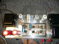
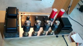
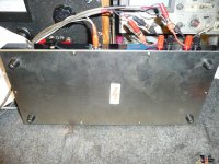
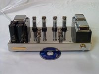
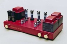
I need a schematic of how to convert a Harmon Kardon Citation II amp from triode top pentode mode.
Right now I have a 270 ohm resistor going from pin 4 of a Kt88 tube to 2nd & 4th connections on output transformer.
What do i need to change?
Any Danes around? Bought a batch of tubes and this one had all prints scrubbed off. However, there was a code on the underside of the tube which revealed it was an ECC81 made by Philips in Copenhagen, Denmark. Horse-shoe getter and ribbed short plates. Strangely enough no date codes (may have been printed on the glass), only a "+" sign after the Copenhagen pyramid symbol. Can anyone shed a light on this?
I have vintage compact floorstanding speakers (JMR-Jean Marie Reynaud) which has a mid woofer installed inside speaker cabinet firing upward, and tweeter and another mid woofer facing forward. Is there specific terminology for this kind of speaker configuration? Not sure if it is called Isobaric configuration or another terminology for it.
If anyone educate me on this would be hugely appreciated.
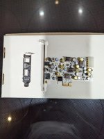
I have a SOtM tX-USBexp card that I'm not using and want to give away. This card is a USB interface that you can add to a PC. I've used them with Windows and Linux.
Hi, I'm looking for advice on a cheaper opamp for the fosi audio za3 that sounds as good as the burson audio v7 live, sparcos lab s 3602 opamps
It is impossible to buy Burson audio v7 live, sparkos labs ss3602 in Turkey and products coming from outside Turkey are subject to 60% tax and products worth more than 30 € are detained at customs, so I am looking for a cheaper opamp with good sound and I am waiting for your advice on this issue.
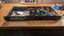
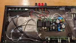
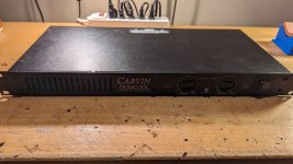
For Sale: ICEPower 125ASX2 amp module in a Carvin DCM200L 1U chassis.
Bandmates blew up original Carvin amp years ago, so I just replaced the Carvin "guts" with an Icepower 125ASX2 stereo module I had. I connected the aux power from module to the amp to drive the preamp / gain control and power / clipping LEDs in front panel.
Both XLR and 1/4" inputs work as inputs. Parallel switch in back will mono channel 1 input to both channels. There is an "EQ Expand" button in front that seems to change sound that also works...
How many ways are there to generate dipole patterns?
Do any of the alternate approaches have particular advantages and disadvantages to learn from?
I've been reading a ton about open baffle designs, ranging from huge baffles to fully "nude" systems, and in all combinations of dipole + monopole combinations across the frequency spectrum.
Since most tweeters are monopole, many designers add tweeters on the back of the baffle/system. I've even seen this on closed box systems. It made me wonder in which ways that kind of solution might be better, different, or worse than dipole tweeters?
Could this extend to the midrange, say, with 2 mids mounted back to back in a tube the diameter of the drivers, wired out of phase?
What would happen as the wavelengths get longer... maybe identical sealed (or ported) chambers front and back, with the drivers again wired out of phase?
I'm curious whether any advantages (or disadvantages) could ensue:
Dipole sound, "closed box" aesthetic?
Instantly change your speaker from being dipole to monopole depending on the music or mood or room placement (e.g. shoved to wall or not) using DSP?
There is an item located in the Netherlands that is for sale on Marktplaats. I cannot register and message the seller because I only have a UK telephone number. Would some kind person be willing to put me in touch with the seller?
Login to view embedded media
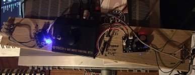
Video equipment connection:
PC -> USB TO 4AES -> 4AES TO HDMI -> HDMI TO 4AES -> AES TO active monitor speakers
4AES is 4-channel AES/EBU digital audio signal, that is, 8-channel audio signal
1. USB TO 4AES: $120
2. HDMI TO 4AES: $190, DSP expansion card: $30
3. 4AES TO HDMI: $258.
USB TO 4AES
1. Supports WIN, Apple, and Android systems, plug and play. There are two models, one is an external USB interface box, and the other is a full-height computer baffle.
HDMI TO 4AES
1. Two HDMI inputs, one HDMI output, and the output supports up to 4K@30Hz.
2. 4 groups of AES/EBU outputs. The audio format required for HDMI transmission is LPCM, with a maximum of 8 channels
3. The DSP function can be expanded. The DSP expansion card is realized through the 4 groups of I2S interfaces on the motherboard. To use the DSP function, you need to use the sigma studio tool and have the USBi tool.
4. With remote control, multiple functions can be realized
If the DSP function is expanded, the remote control function can be customized
Dolby CP750/CP650 control expansion, etc.
4AES TO HDMI
1. 4 groups of AES/EBU input (can be changed to 8-channel analog input through appropriate modification), 1 HDMI output.
2. 4AES/EBU input can be input through DB25 or RJ45 interface.
3. Each group of AES/EBU input has ASRC sampling conversion function. The audio in HDMI is output at a fixed 48KH sampling rate.
4. Volume adjustment and other algorithms can be realized through the expanded DSP function.
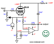
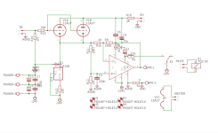
I decided to make a tube buffered IC amp, although tubers or gaincloners won't like it.
And I liked tubecad's tube buffered (with CCS) chipamp design. However, I have 12AU7, 5751 and a few 12AX7. To be honest, I didn't want to buy a 6DJ8 just for this project.
However, the CCS on the cathode of the tube is 10ma and this would be a high bias for the tubes I have. So I decided to use 2x parallel 12au7. This would give me a quiet bias of 5ma per cathode.
I decided to use LM317L, which I have used before and was happy with, set to 10ma, as the CCS.
And this is the circuit that came out..
What I want to ask is, this circuit gives THD values like 0.05% in the simulation.. Also, according to the FFT results, the weighted harmonic is 2. (A harmonic that I personally like) Do you think something like this is possible? Or is this circuit worth making?
Thanks in advance..
PS: 317's resistor should be 120 not 150...
Anyone is the US willing to design, for a fee, DXF files for me to submit to Modushop for panels? I did some searches in various fora, but did not get anything.
I would provide scans of hand-generated design on graph paper, with appropriate dimensional information. Punching is only what I would news, no graphics or labels to be engraved.
I would like to reuse my Carver power supply board for DIY amp boards. The board has 2 bridge rectifiers that supply different voltages. This would be useful for my project. There were thermal switches on the old amp boards. Can I use the board without them? Also, would this affect my speaker delay protection circuit on board ?
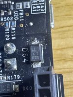
I am trying to identify the part in the photo below market TX8FGS7, I believe its a TVS diode. I have looked online but can't find a data sheet or equivalent could anyone offer and advice on a UK supplier, data sheet or equivalent.
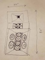
all right i'm attaching some sketches to help you visualize what i have in mind ...
this design has gone through a bunch of iterations and some aspects of it keep sort of vacillating which i will address later ...
for now i will just describe what the current iteration is, as depicted in the sketches ...
5-way system consisting of a center subwoofer stack that goes between the two main 4-way speakers ...
both speakers and subwoofer stack are 80" tall ( to fit in basements ) and the width is 32" for speakers because that's 1/3 of 96" that plywood comes in ... and 2 x 32" for the subwoofer stack. each subwoofer module is 25.5 x 32 x 40 inches, with a total of four modules. 25.5" is just 24" + 2 thicknesses of plywood. the main speakers would have approximately similar depth ( about 2 feet ) but since they curve towards the listener they don't have any hard number for their depth ...
in my sketches you can also see a 75" TV mounted on the subwoofer stack ... that is indeed where the TV will go but it doesn't have to be 75" ... although the width of 75" matches the width of the subwoofer stack exactly, which may or may not be a coincidence ...
total system width would be about 12 feet which is about as narrow as i could get it but it should allow it to fit in most living rooms outside of NYC and SF.
in the current iteration of the design the driver compliment is as follows
3 khz - 20 khz https://www.bmsspeakers.com/index.php-48.html?id=4526nd2 x 2 array of 8 ohm drivers in series parallel for a 8 ohm load
the horn array will consist of four identical but not symmetrical horns that must be 3D printed
that is to say the arrangement of the four horns will be symmetrical but the horns themselves will be asymmetrical
the asymmetry will be used to bring the drivers as close to each other as possible, with magnets almost touching each other
all in all 8 identical horns will have to be 3D printed from a single file
main crossover will be MiniDSP 4X10 HD and it will plug in directly into the TV via optical Toslink ... i will throw some protection caps on the compression drivers to be safe as well ... the 80 hz crossover point will be realized internally to the 4-channel DSP amplifier that will power the woofers and subs
the TV will ultimately be the source, it will probably be a 2022 Mini-LED TV from either Samsung or Sony. i had a 2021 Samsung Mini-Led that i used as a source like this via optical output and it worked really well as the TV could do YouTube, Netflix and Spotify ... unfortunately it was a first generation Mini-LED and had a flicker so i sent it back to Costco ... in 2022 Samsung is coming out with 2nd generation Mini-LED and Sony is entering the Mini-LED market as well ... it will take time for prices on new models to drop but it will also take time for me to design and build this system ...
there will be a total of 3 amplifiers:
QSC PLX 2402 ( which i already own ) will power the 8" midbass array at 2 ohm, and will have a Noctua fan mod
QSC CX 404 ( four channel ) is $400 used on Ebay and will power all compression drivers, it will have the same Noctua fan mod
JBL Crown DSI 2.0 MA4 ( four channel ) will power both subwoofers and 12" woofers. this amp is expensive but it packs a lot of power and DSP and i may need those.
now for where the design keeps vacillating ...
i sometimes wonder if it's best to use 12" or 15" JBL woofers and whether it is best to use 8" or 6" Eighteen Sound tetracoil midbass ...
i sometimes wonder if the midbass should be vented or sealed ...
i sometimes wonder whether to use BMS 4592 mid, 4594 mid or 4599 mid ... the 1.4" throat versions can be used with B&C ME464 horn while the 2" versions would need either SEOS 30 horn or a DIY horn with 3D printed throat adapter and plywood mouth
i sometimes wonder if the system should be 5-way or 6-way ... in case of 6-way it would have an array of Six Beyma CP-12 Supertweeters crossed at 8 khz ...
i sometimes wonder if for tweeters i should go with BMS 4526 or Faital HF106 ... and in case of faital whether to use 1, 2, or 4 ... or if using Supertweeters perhaps a single Faital HF1440 ...
the reason i am using an array of tweeters like this is 2 fold:
- it lower distortion by quadrupling throat area thus lowering compression and distortion ...
- it doubles the coverage angle at the extreme high frequencies where horns begin to beam ...
yes i realize there is the issue of comb filtering and that's why i keep vacillating on what is the best solution in that area ...
as for what i'm trying to achieve with this is it is intended to be my main system for the foreseeable future - it isn't intended as any sort of exercise - it is intended to be THE system i use whenever i want to listen to music or watch music videos or movies at maximum volume ... it is intended to have the absolutely maximum performance level possible within what can be achieved in a system of reasonable size and cost ... spouse approval factor is not a consideration but i want to challenge myself by keeping it as compact and cost effective as possible - i could not respect myself if i went sloppy and simply started to mindlessly pile on heaps of subwoofers using "the more the merrier" approach ...
this system will be acoustically in a large space as the house is an open concept plan with one continuous space spanning from the porch to the patio and also both first and 2nd floors ... it's basically in a "living room" but it's also the same space as an eat in kitchen and sunroom and pretty much open to the entire rest of the house except bedrooms and bathrooms. the floor is wooden as there is basement below. the ceiling is sloped from 10 to 20 foot high. all other surfaces are fairly thin drywall and lots of windows - the house is mostly acoustically transparent - i don't expect much standing wave issues as i used to have in an apartment in a concrete building in NYC. on the other hand where i could fill that apartment with a single sealed 18" TC Sounds LMS subwoofer because those cinder block walls and concrete floors and ceilings trapped the bass and kept it resonating in the space ... by contrast in the space i'm currently in the bass will simply spread through the house and then leak out to the street so i need much higher bass output even for my listening position that will be about 8 feet away from TV screen ...
i have also been on a professional sound reinforcement forum discussing hearing damage and considerations for designing very high SPL systems like this until they eventually told me to go here instead because i'm not a sound reinforcement professional ... but before i was shown the door one good dude did give me a list of AES papers on hearing damage to read ( he wrote most of them ) so i'm currently reading that ...
the system in question is definitely deep into hearing damage territory but i'm trying to quantify it more accurately so i can optimize for lowest audible distortion at highest allowable levels and do so with the most compact and affordable system ... also read recently a very nifty article about audibility of distortion at different frequencies which allowed me to reduce the size of subwoofer array since as it turns out we are essentially deaf to distortion at subwoofer frequencies ...
don't be shy - i want to hear your criticism ! i will eventually hear it one way or the other and i would much rather hear it BEFORE i start building !
to conclude this post i will throw in some sample material i enjoy so that you can have an idea of what i will be trying to reproduce with this system:
I would like to build a hi-end two way loudspeaker with a mid-woofer 6-8” in size, what driver would you suggest? I know this is the most boring speaker size in the world, but it is the most efficient size, in sound quality that is!
i want great bass and a fantastic midrange of course, and this is for a small room!
Does anyone have any schematics for any proven "custom" crossovers for the BMS4590 ( 8 ohm ones) I have been unsucessfully attempting the flatten the response of these drivers by adding notch filters etc. ( running in a 200hz Le Cleach horn crossed actively @ 350hz)
I have looked on the web and have seen ones on german pages for eckhorns etc, and but i don't understand from my simple calcs what they are doing as the notch filters seem to be in places in the freq range where i don't think i need them.
I'm fixing an old mixer and need help identifying replacements for two potentiometers
I'm able to find similar but don't know what kind of taper they have
They both seem to be made by ALPS and are externaly the same (dimensions bellow)
one has XC502 on the pot and 5kzy on the schematic and measures 5kohm - function: preamp gain
the other has ac503 on the pot and 50KG on the schematic, has detent at 12 o'clock - function: aux send
shaft lenght 18mm, including collar 23mm
shaft diameter 6mm
total lenght (excluding terminals) 30mm
body 9,85mm x 11,85mm
A pair of which are enroute to me. Plan is to use in a small ob with a sub. People seem to like this diver inspite of the 15khz Mt. Everest in the graph. Infact it is not mentioned at all. Do you all think this will need attention?
Sorry for getting theoretical here. I'm kicking around an idea in my head for next year, when my cards are paid off. I have a pair of 2-way speakers on stands. I am thinking of adding a bass section to fit below them.
The existing speakers use Revelator 18W/4531 and are about 12" wide. They're rather large due to the BR.
The plan is to seal them and run the upper section from around 200 to 300 Hz up. The bass section should be simple (sealed or BR) and will incorporate a 3-way Hypex plate amp. I'll be converting the passive speakers to fully active.
The bass section should be about 10" wide. I could see a pair of 8" woofers, or a pair of side mounted 10" drivers...
Bass should be solid, convincing but not looking to spend ultimate dollars. Also, plan on fully leveraging the EQ capability of the plate amp for room integration. Thoughts?
Kia ora and hello!
Thank you for having me here. I'm looking forward to learning a bunch of things, and hopefully getting some help to use the a schematic to make a replacement PCB I broke, but with better (newer) components.
Have a great day 🙂
Hello everyone! Mi name is Enrique Spinelli. I have been working for many years on analog instrumentation circuits, mainly focusing on biopotential amplifiers. Currently, as a hobby, I am starting with low-noise balanced microphone preamps. I don’t have much experience in this area, but I hope to take it through this forum... I believe that some of my circuit designs could be adapted for audio applications. Best regards!
Hello
I started few years ago to repare some old amps. Made some mistakes, learned a lot, yet still learning.
Addicted to old Sansui AUx17 series.
Open to new technologies, I love my Fiio M23.
It's time for me to dig deeper into the DIY audio. So, what could be better than this forum?
Hi I am contemplating committing to a three way speaker design despite my preference for my current two way speakers compared with various compression drivers horn combinations in both two way and three way configuration. The current speaker is comprised of a Beyma 15G40 15" woofer and CP755ND 1.4" compression drivers mounted to wave guides actively crossed crossed at 700hz per channel. I was originally considering supplementing the bass section of the speaker with a second 15" woofer in the hopes of achieving a lower bass response however after some suggestions from forum members I am now considering an alternative design.
These are the three way designs I am considering. Any suggestions are appreciated.
-A Ciare 15.00SW 15" subwoofer driver crossed at 100hz, a single or pair of Beyma 10MI100 10" drivers in an MTM or TMM configuration operating from 100hz to 900hz, and a Beyma CP755ND from 900hz to 20khz
-A Ciare 15.00SW crossed at 100hz, a Beyma 15MI100 crossed from 100hz to 900hz, a CP755ND from 900hz to 20khz
-A Beyma 15G40 crossed at 250hz, a Beyma 15MI100 crossed from 250hz to 900hz, a CP755ND from 900hz to 20khz
The primary question questions are, is there an advantage to using a single 10" driver versus multiple 10" drivers in an MTM or TMM configuration? And is there an advantage to incorporating to a single 10" or multiple 10" drivers for midrange duties, compared with a single 15" driver? Any help is appreciated. Thanks.
I wasn’t entirely sure of where to post this thread. I have a stack of Hafler pro amps, and I need to replace a couple of the fans in them. Amps use lateral MOSFETs that are hard to find and very expensive when you do. So I want to make sure that I have enough cooling for them. The fans are not overly loud, but it would be nice to make them a bit lower. I have a bunch of the Yamaha PC-9501n amplifiers, and they are dead quiet.
This is the current fan that is in them, as you can see the one in my hand is broken.
It is a 5 blade fan that draws 350 mA, I found that is spins at about 2550 rpm. I cannot find a spec for air volume on it. I did find another fan from the same company that has eight blades and has a speed of 2800 rpm. It draws 550 mA and moves a volume of 115 cfm. Clearly the fan in my amps will move less volume, but I don’t know how much less.
I purchased this van last night, it is referred to as one of the best performing fans if you want ultra quiet.
It’s spins at a speed of 2000 RPM and draws only 140mA. I found it moves a volume of 60 CFM. Do any of you think that this fan will be up to the task of keeping these MOSFETs cool?
You can see there is some space above the original fan. I was reading that there is another fan that may be even better, but it is 30 mm thick and not all scenarios can support that. I ordered a three pack of them, Phantek T-30.
It spins at a higher speed of 3000 RPM, draws like 360 mA which is closer to the original and it moves over 100 CFM. I could run it at the lower speed of 2000 RPM and it will move 67 CFM, of course faster spin, speed and air movement equals more noise. So I was hoping to get your input on this, do you think that the Noctua up to the task? If it is, I will buy nine more and all of the Haflers with it. I’m just not sure how many degrees of difference on the heat sink there will be if you cut the air volume movement down. With the original fans, the amp do run warm. The amplifiers are biased to about 100 mA per output device.
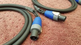
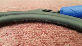
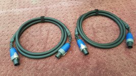
Im looking to buy a stereo pair of this speaker cable in lenght 2,4-3 meter.Im looking terminated or untermineted cable. Price should be up to 150 euro. If you have this cable for sale plese contact me.
I picked up this used Bose Acoustimass 10 IV speaker system. Speakers seem to work fine, but the subwoofer does not make any noise. So I took apart the unit and found some obviously failed (burnt) components:
1x 3.14 A @ 250V main circuit fuse
1x bridge rectifier GBU601. there's actually two of these on the board, one is obviously burnt and the other does not seem to have any anomalies like shorts. However I figure may as well replace both.
2x diode. This is tricky because the only markings I see on it are: "617 402". No current rating or anything else. How do I figure what to replace this with?
There are also transistors SGSD200 (PNP) and SGSD100 (NPN). Couldn't seem to do the typical diode test on these, maybe due to how they are wired on the board. There's no obvious shorts, but I wouldn't mind replacing these just to be safe. One of these does seem slightly darkened. The part numbers show up as obsolete on Digikey. What do I look for in order to source a suitable replacement?
So plan is to just replace the components listed above, help identifying what diode and transistor to use appreciated. Everything else on the board otherwise looks fine. If there's other thoughts, let me know? Thanks!
See attached picture.
EDIT: I also just discovered that the small SMD resistor below the "O" in Bose may also be blow. See my post #15 below.
Hi! I'd like to build some 3 way open baffle using Beyma 12P80ND v2 as a mid and Faital Pro 10AK compression driver for the high frequency. For the low frequency I will decide later the driver(s). Do you think it can be a good choice? Any particular horn in mind? I am looking at Faital Pro LTH 102, looks OK. Any ideas for a good passive crossover is highly-appreciated. Thank you!
so I have tested both R+ and R- by wiring them single-ended and they are working fine.
I want to try testing them now in balanced mode. And I have connected...
hot pin of the XLR (pin2) to R+ PCB (this XLR cable is connected to the XLR output of DAC. Volume can be controlled in the DAC so I set the volume to -90db)
cold pin (pin3) to R- PCB
positive terminal of speaker was connected to R- PCB output
negative terminal of speaker was connected to R+ PCB output
This connection results in massive hum. Do I need to connect the XLR ground to the PCB ground?
Hi,
I’m currently tried to repair a pro audio compressor I bought month or so ago. It’s a Golden Age comp 554, it’s in a 500 series module that’s a copy of a Neve diode bridge compressor. Every works fine on the compressor, except the compression circuit doesn’t engage. Signal runs through it fine and output gain works. I’ve checked all of the caps so far and they are all fine. I’m confused as to whats stopping the circuit from engaging.
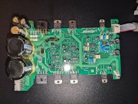
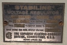
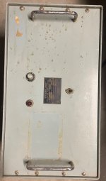
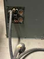
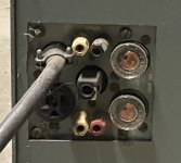
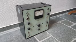
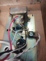
I picked this up years ago. Employer wanted to toss it but asked to keep it. It is beast and very heavy > 50lbs. I believe it was used to regulate voltage to scientific instruments. I’m guessing it was from the 50-60s.
Others have told me to scrap it and some have said it could be used to regulate power to a tube amp. Looking for any additional thoughts. Moreover, I can no longer keep it and would like to get it to a new home where it can be appreciated.
Moving on a superbly built and excellent sounding SissySIT, purchased here towards the end of last year.
500va toroidy trafo 230Vac
Teabag PSU board
Thf51 matched pair
400 deep amp 3U modushop
Cinemag CMOQ-4 high nickel trafos
This owes me £925.
Collection only please from Edinburgh, Scotland. I could ship in UK at buyers cost and risk - but please note it will take me a while to source proper packaging.
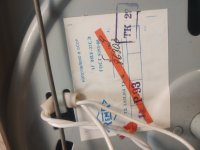
Got a multi broken Thule IA250B that I will try to restore. There are several issues with one being the preamp voltage regulators 317/337 that as std have a what looks like 1uF 50Volt capacitors. I have attached a picture and ofc googled but can't determine if its a ceramic or tantalum capacitor . I have the schematic but its not the same version, in the schematic it says 3,3uF electrolytic.
Not sure whether this is the best section for this topic.
I've put together a simple "integrated" amp for listening to my turntable using an off the shelf Class D board and phono preamp (see links and poor quality photo below). These are both powered from the same 19v laptop supply. I have butchered an input selector switch unit to give RCA inputs and allow other (line) inputs. I have also added a volume pot.
Currently it's not mounted in a proper case, but boards are screwed to a plank of wood, and it's all working absolutely fine with (almost) all grounds connected and no shielding of signal wires. For now I've been connecting the turntable ground wire to the RCA plug grounds which has been effective in cancelling any hum. There's a labelled ground point on the phono preamp board which I've not needed to connect.
I'm happy enough with the performance of this that I've decided to mount it on a proper metal chassis. It sounds better than it has any right to driving some quite decent (and large) speakers. Not high end but definitely HiFi.
I'm trying to plan how best to lay it out and wondering how to approach grounding. I'm not overly worried about obvious unwanted hum as it works fine as is, but I'd like to follow best practice so that it works as well as it can.
Below are all the grounding points:
signal and power grounds on 2 circuit boards, plus the turntable ground on the preamp board.
PSU -ve
RCA socket grounds
Potentiometer ground
the (aluminium) case, and I would assume I would connect the binding post for turntable ground directly to this.
I'm thinking of 3 basic approaches:
1. Connect all signal grounds and power grounds logically to each other. Ground the TT and PSU and RCA sockets to the case. This is roughly the current scheme, and it works. I could potentially use shielded wiring internally with this approach.
2. Only connect positive signal and power wiring, connect grounds to casework at nearest point
3. Only connect positive signal and power wiring, connect grounds to casework at common point (star) in this case I'd probably keep RCA socket grounds insulated from the case and use a bar (solid copper wire) to tie their grounds together.
It's very possible I'm missing something obvious here. Hope it all makes sense. I realise it's quite a basic project but the aim is to do it right - and squeeze as much performance as possible out of these basic components.
I’d welcome any thoughts or suggestions on what’s likely to be the best way to hook it all up.
Hi all,
I have a linn klout that the right side amp module isn’t working and unless I unplug the right side it just blows fuses, does anyone have a schematic? Seeing as it’s nearly 30yrs old there’s no support anymore from linn and there are no linn dealers in upstate NY where I now live now (originally from the uk where I purchased my entire linn system).
Hi, I have a Vibe mono 21k. When i use Digital Meter set to DC, One wire to RCA ground ( it doesn't matter if rca is connected) and next to amp body (hole for mounting screw) i see 0,3v+ When the equipment was not in use, and drop to 0,145v. after listening music, i can see 3volts and above, this is droping to 0,150 volts.
Amplifier have DC Offset, 0,520volt output without signal...
Any tips to Fix this error? This cause: Head unit rca voltage loss, weak sound, distortions. Amplifier does not touch extra ground. I checked another amplifier, Hifonics brx 12000 and problem is this same.
Thanks.
There was some interest in another thread about the modern Quad inductors that form a portion of the delay line in the 63's and newer Quad electrostatic loudspeakers.
Strangely, the British electronics in these speakers is quite robust. But over the 24+ years I've been fixing quads, i've seen just about every failure you can have. I've only seen a couple damaged inductors and they were the results of massive overdriving of the speaker. Below is my knowledge of these inductors, although I haven't really dug into them very deeply (both metaphorically and physically) which you'd want to do if you were going to reproduce them.
The inductors are air core units with a second shorting winding that increases the inductance dramatically beyond what a single coil of this size and wire gauge is capable of. The inductance is about 2.7H each if my measurements are correct. The attachment below shows my method and results. (NOTE: The DCR is in Kohms not ohms as noted on the sheet. And I went back and re-measured the inductor resistance and got the same numbers as the first two inductors; I beleive all inductors are identical). I used a function generator, a resistor and a voltmeter to measure the inductor by forming an AC voltage divider. Using the fact that and inductor has an impedance of: Z = 2 * PI * f * L, I was able to calculate L because I know, Z, and f.
As seen in the pictures, the copper coil is sitting in a plastic "bobbin" with three leads which are soldered to the delay line circuit board. The entire bobbin, and actually the entire delay line circuit board is encapsulated in bee's wax which makes these things easy to work on.
Two of the leads are connected via a buss bar inside the bobbin, and the third (middle) lead runs from the center of the coil. The shorting coil is attached to both the left and right attachment points on the buss bar (forming a short through that bar. And the main inductor coil is attached to one side of the buss bar, at the outside of the coil and the other end is attached to the center lead coming from the middle of the coil.
I don't have a feel for how the shorting coil is arranged relative to the main coil. I'd think it would be bifilar wound, but I have never completely unpotted one of these to check it out.
The way I've seen these fail is that the very fine wire breaks near the solder connection at the buss bar. It appears that the wire overheads and melts, but on come specimens the wire looks thinned which doesn't make sense with a pure melting failure mechanism.
To fix them, I melt the wax around the buss bar and in the center of the coil and using a short piece of jumper wire, I re-solder the fine magnet wire to the jumper and then the jumper to the buss bar. I use the jumper wire because without un-potting the entire coil, the wire where it breaks is too short to reach the buss bar.
Here's a couple pictures of the inductor including one through my stereo-microscope eyepiece. Taking a picture with my cell phone through the eyepiece is a real kludge but works reasonably well to document things.
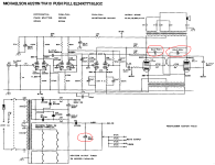
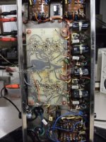
Bevor I start replacements and troubleshooting on his device, I want to know, if there descriptions for upgrades in the circuit design so that this unwanted oscillations is no longer present.
Who can upload this associated circuit diagram ?
How many different versions are exist at whole of the TVA-10 and which of them shows the above mentioned deficiencies in the circuit design ?
Thanks for any advices in advance.
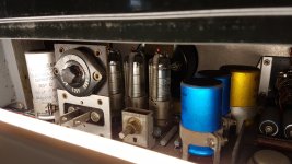
According the attached images there are a version with two capacitors and a version with four capacitors behind the rectifier
Additional a version without PCB and a version with PCB (main board) for input and driver stage
The version with PCB exist with two different input and driver tube configurations (3x2 and 2x3 lines) and thus two different PCB layouts
As I know, all versions have partridge-transformers and the McIntosh Unity coupled circuit in use - very important for a tight and clean bass character.
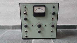
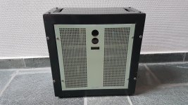
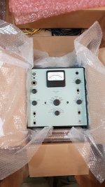
The 2603 is about 55 years old, it dates back to 1966~1969.
This preamp needs some care, but the overall condition is good, and fair given its age.
Was planning to restore it but never got to it so I'm letting it go.
ASKING PRICE € 1.250,00 + shipping
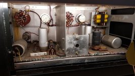
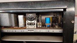
There are 6 or more tubes in the circuitry, and as far as I can tell most, if not all of these tubes are still available in case you need a replacement one day.
I have no idea of the condition of these tubes. Neither do I know if the capacitors need replacement. I never switched it on; it was sitting in my music studio as an eye catcher, waiting to be restored one day. All parts are there. And the unit looks well preserved, which is a good indicator.
It could be non functioning, and require quite some work;
It could require just a minimal check up and of you go.
I can give no guarantees. The unit is sold as is.
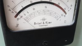
To know how it sounds, look on Youtube for:"Brüel & Kjaer Type 2603 vacuum tube preamp"
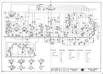
I collected several PDF's of this device and line of equipment, including the schematics etc.
I will happily send them to you (saves you some research)
Please note: this preamp does not work with regular XLR mics - although you could probably mod it to do so.
It does seem to work with line signals as a DI, as you can see from the linked video.
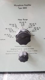
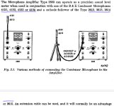
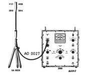
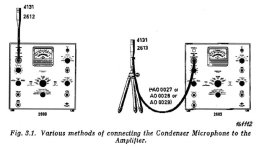
It accepts the following mic capsules from B&K: 4131, 4132, 4133, 4134 ..
Combine the above capsules with a B&K "Cathode Follower" type 2612, 2613, 2614, or 2615.
The above parts are available on Reverb and through other places and sellers.
---
The inputs and outputs require a type of B&K plug that is hard to find. Luckily these connections accept simple banana plugs too, which fit like a glove. The ins and outs are basically (unbalanced) line signals. One could easily fashion a set of adapter cables that go from banana plugs (male) to 1/4" jack (female) for day to day use.
---
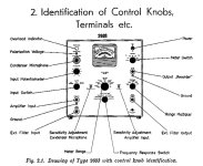
Connections are as follows:
"Amplifier input" = the main line input, which accepts a banana plug
The small hole underneath this and other plugs is ground; accepting a banana plug as well
"External Filter Input" = actually an output !! Clean signal from this out
"Recorder" = allegedly this is a more fuzzy / slightly distorted output
---
The overall gain is adjustable by the "Input Potentiometer" and "Meter Range" switch.
---
The power connector is a Nema 5-15R.
Adapters are available to regular IEC etc.
Alternatively you can connect a power cord directly using the screws adjacent to the inlet pins.
---
My location is Belgium. Items are shipped safe and secure with tracking etc.
Please contact me for a shipping quote for your specific location.
I'll be happy to make you a personal quote.
I recently did some measurements on some B&W 8" drivers from one of their subwoofers. Using the added mass method I kept getting the message stating I hadn't added enough mass to lower Fs enough. I eventually plonked on a tape measure on top of the blue tac that I had run out of. I think this gave me an added mass of about 360g.
Voila, VAS measured and came out at 9.2 with an MMS of 101g.
I forgot to save this so I redid it a day or so later. Didn't add as much mass this time, can't remember exactly how much, but it have me a VAS of approx 12 and Mms in the 70g region.
Quite a change from my initial attemp and makes for different results in WinIsd obviously.
What do I need to for repeatable or more accurate results?
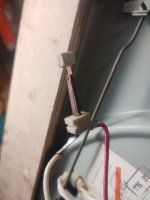
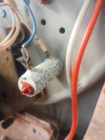
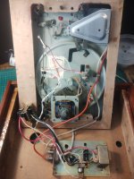
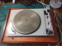
Well. Here is the inside of a 1969 Soviet era Turntable. It's a doozy😜
Apart from the unidentifiable cylinder that looks like it's been at the bottom of the ocean since 1969, the tone arm that seems to suddenly have a ton of tracking force, there is an unidentifiable contact switch hanging loose.
It's a brick.
Oh the turntable turns......kind of.
But it looks soooooo cool.
I could make this a quiz?
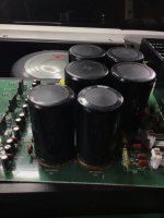
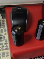
I acquired this amp three months ago, but with life getting in the way, I literally only powered it up last Monday afternoon. Essentially it runs through a start up procedure, the screen works, a fair bit of relay clicking and then it switches off. My own fault for not checking it sooner. I’m half decent with investigating and repairing, and even managed to get the schematics from XTZ. A lot of Chinese though and could be clearer. One 4700uf 63v cap on the power supply board had leaked, actually leaving a leg on the board. Lots of nasty glue everywhere but I’ve cleaned that away, checked the four main 12000uf caps, and they test within spec. I’ve replaced both 4700uf caps, sorted out a couple if dry joints and thought that obviously bad cap could be the issue. No. Found more dry joints on various voltage regulators and elsewhere. Still no joy. There is no response to any control input apart from power on. The overall build of this thing makes it worth the effort, but if anyone has any ideas they would be much appreciated. I’ve never seen an amp with so many screws, it’s depressing!
Hi guys.
I have been a member for a very long time of this site, but haven't got into the introduction of myself.
Anyway, I reside in Denmark close to Copenhagen and enjoy good clean analog audio.
My system consists of a XTZ Class A-100, Dali Mentor 6 speaker and my precious Sony CDP-XA555ES.
Hi All.
I have a PPI A600.2 in which R171 (obviously just a link) has gone open circuit.
I'm also not sure about the lump of solder on the edge of the board screw just below that.
Should I be concerned about either of these things ?
As yet I have not done any further testing.
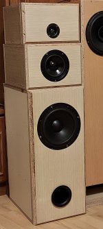
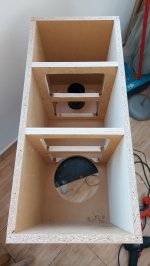
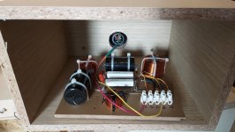
Hello,
Mostly ignorant of speakers rules ,white hair.
In the picture is what i build for home use.
Three separate boxes because this would allow new variants.
They need to be glued, but I'm not sure even if it doesn't sound bad .
Speakers Ciare HWB200-8 ,Visaton w130s,Monacor DT25N.
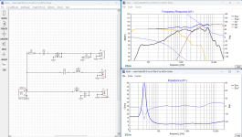
Simple filter (first and second order (?)) designed with some help with Xsim and FPGraphTracer.
Bass box internal dimensions 61.6x25x35cm, Vnet=51.5L(WinISD), port Dv7.2cm Lv15cm double front panel and two transverse reinforcements.
Please ignore the high standards you have for your works and give me some tips .
What can be done better,bass box dimensions ratio ,port and speaker location...
Thank you and sorry for any mistakes, it's google translate.
Over the years I've analized / modded / built a number of onboard bass preamps, for some of which there isn't much info out there, and I thought it would be nice to share all the info I have in a single thread. As I go along I'll update this with an index to the relevant posts. I'll also discuss some general topics such as opamp choice (post #2, post #27 and some suggestions for SMD opamps by @Passinwind in post #23) and pickup loading (post #3). These are some of the preamps I'll cover, in no particular order:
- A DIY 2-band Baxandall (post #4) I designed and made for a friend's Warmoth Jazz Bass
- Mighty Mite MM114 (post #6, no longer produced, see page 3 of this catalogue), it came in a Tobias Toby Deluxe 5 I bought back in 2001. An opamp-based, 2-band Baxandall eq with a couple of unusual twists
- Seymour Duncan STC-2P (post #8) and STC-2ASB (the Steve Bailey version, post #9), used in two Warmoth builds. Both are 2-band eq's that use opamps and transistor-based gyrators that lend themselves to many interesting mods (post #12 ff) Edit 4-Nov-24: There was a small mistake in the previous posts, corrected schematics and sim files in post #10, plus PCB component layout and wiring diagram.
- An analysis of the 2-band Stingray preamp (post #16) and a DIY version based on it (post #17), significantly modded to get a more uniform response and to be able to use standard, easy to find pots
- Info about the 3-band Stingray preamp (post #20) for completeness (I have no experience with it) and possible mods (post #28)
Comments and additions always welcome.
Edit: the attached onboardbass.txt file contains the opamp and transistor models required for some of the simulation files posted below.
Want to use 6B4G as output tube in a SE amp with Ia 45mA. 2A3 is said to have Ua max 300V, but the specs for 6B4G says 325V with fixed bias AB at 40mA. Anyone who have tried 325V?
Looking for an Amp Camp Amp Mini amplifier or kit. I know I can buy a kit in de diyaudio store but there are probably a lot of them out there that are unused or not even build yet so maybe I can give it a second life. Preferably in europe due to delivery costs and import taxes.
Does anyone know where can we buy toroidal transformers in Mumbai ? I have contacted one person BE Torodial Transformer but he doesn't communicate properly. Can anyone please let me know anyone else who manufactures transformers?
It would be greatly appreciated if someone could tell me whether the following well-known audio site from Phoenix AZ is still operating?
alan m. kafton / audio excellence az, inc
940 east cavalier drive
phoenix, AZ 85014-1912 USA
602-277-3737
I've been trying to order his Ground Breaker Adaptor Set for my Audiodharma Cable Cooker but have yet to receive any response despite three emails
(https://www.thecablecooker.com/order/ ) and unable to get through by phone.
I have 2 pairs of Siemens D3A and Phico Type 26 that I planned to build something but never got time to do.
The D3A were bought NOS, used for less than 10 hours. The Phico 26 were bought tested NOS but I still haven't got them used.
Asking $130 including shipping worldwide for both pairs. PP fee is not included though.
I'm wondering if anyone here has actually built/designed a power conditioner. I'm asking because I suspect my main systems have less-than-optimal conditions due to switching power supplies, class D amps, and computers being part of the system.
The prices I see on the ones which look like good quality are sky high. Are they terribly complicated to build?
If an amp is with a FET (mosfet or jfet) input stage, can I omit the DC-blocking feedback cap?
I need real world experience. As you know, in the simulation, everything is perfect.
I'm starting this thread to talk about an interesting and new method for "removing" group delay from a continuous audio signal using reverse-IIR filtering.
Background: When you perform "analog style" filtering on a signal, that filter does not output all frequencies at the same time. Instead, frequencies emerge from the filter at different times. This is a consequence of what the filter is doing in the frequency domain (e.g. to the frequency response) - the filter automatically produces non-linear phase changes to the output signal. The result is a distortion of the time-domain waveform, because the appearance in time of various passed frequency components has been altered compared to the input. This sort of phase-domain distortion does not in any way change the magnitude of the frequency component (the frequency response) but the signal in the time domain may look badly distorted. This effect is called by different names, including phase distortion and group delay distortion. When the distortion grows large enough, it is possible to perceive a change to the "tone" of the signal. At lower levels it becomes imperceptable/inaudible. in general, the steeper the filter the worse the group delay distortion and this puts some limits on how steep of a filter we can use for a loudspeaker crossover. With FIR filtering, the situation is different. Phase and amplitude of the filter are independent of each other and this means it is possible to choose the phase to be linear (meaning the group delay is flat). Until now, FIR processing was essentially (to the best of my knowledge) the only practical way to implement a filter with a linear phase response.
More Background: Forward-Backward IIR processing. Someone realized that if you had some finite quantity of sampled audio you could process it first in the normal "forward" direction, and then also in the "backwards" direction. The filter's magnitude changes are applied twice. But the changes in the phase of the signal are exactly reversed, undone, and set back to zero in the "reverse" pass of the filter. What is happening is that the time shift of a given frequency that occurs in the forward direction is exactly equal to the time shft from the reverse pass, but these are opposite in their time "direction" and so they cancel. The result is zero phase distortion, zilch, nada! Let's do it says the crowd. Ah, but implementing this is not so simple. In the forward pass the ringing tail of the signal requires some time to "die down" This extends the duration of the original signal by the length of the tail. This tail must also be processed in the reverse pass in order for it to be brought back in time to its original "place". But if you have a continuous signal, things get tricky. There have been attempts at overlap-and-add methods to process chunks of a continuous signal and then sort of stitch them together but this typically leads to end effects and other problems, and the algorithm is a bit messy.
To the rescue and something that I belive is completely novel is the work by Martin Vicanek that is described in his whitepaper "A New Reverse IIR Filtering Algorithm": https://www.vicanek.de/articles/ReverseIIR.pdf
I will not get into the gory details of the algorithm too much here. However, in the whitepaper Martin describes a way to take the "Infinite Impulse Response" of the IIR filter, truncate it to make it an FIR response, and then reverse the FIR as blocks in order to reverse the poles of the filter. It's frankly some brilliant work that completely eliminates the need for block processing. The only inputs to the algorithm are previous INPUT samples. There is no longer the feedback from output samples because of the re-formulation of the IIR as an FIR (which is then reversed). This allows for continuous "forward only" processing of the audio signal, and this can go on indefinitely. Best of all, the number of operations required for the processing is much less than the equivalent FIR and latency is much less than reverse-IIR block processing methods.
So, how does this help with loudspeaker group delay? While reading Martin's whitepaper I recalled that the group delay from the summed outputs of an Nth order crossover (the sum of the lowpass and highpass filters that make up the crossover) is the same as the group delay from an all-pass filter of order N/2. An example of this is a 4th order Linkwitz-Riley crossover, which is constructed from two second order Butterworth filter (each having the same pole frequency and Q=0.707) run in series. The LR4 has the EXACT same group delay as a second order allpass filter with the same Fc and Q. So, to make a linear phase LR4 crossover we can implement the allpass response, "in reverse" via the RIIR filter, upstream of the crossover to "pre-distort" the phase of the signal so that after it passes through the LR4 and undergoes an "in air" summation the phase remains unchanged.
The applicability of this technique is very broad. This is because we only need to find the group delay response of the loudspeaker that results from the crossover filters and other sources of delay, construct approximately the same group delay response using only all-pass filters, and then apply those all-pass filters in reverse using the RIIR filter. It doesn't matter what order the crossover may be or what the source of the group delay, as long as you can model or measure it you can cancel most or all of it depending on how close a match you can get via allpass filters. My recent effort to do some group delaey audibility testing, as well as what has been repoted in the literature about group delay, indicates that group delay does not need to be zero but only below some threshold to remain inaudible because human hearing is just not all that sensitive to it. But what (to me) is interesting as someone interested in new frontiers in crossover design, is that filters that previous had too high of a group delay response because they were "very steep" can now be corrected to have as low of a group delay as you wish. This starts to blur the lines between IIR and FIR processing and what each type can accompllish, and I find that pretty interesting stuff.
So, are there any downsides? Well, not really but there is a consequence to the RIIR algorithm: latency. When I described how the algorithm works, above, I mentioned that the IIR impulse response is truncated to become an FIR filter. This truncation introduces error because you are at some point setting the remaining part of the impulse "tail" to zero. This is a source of error or noise in the output signal. The more of the tail you retain, the lower is the added "noise" signal. Luckily Martin provides a way to determine how much of the tail needs to be retained when given some signal to noise ratio that is desired. Also, because the tails from poles located at lower frequencies last longer than for higher frequencies, RIIR filtering for filters with lower pole frequencies requires increasing latency. But luckily the tail decays exponentially, and so the latency is not too severe. In a test trial I ran a 1kHz 2nd order allpass as an RIIR filter. This required 128 samples of latency at 96kHz, which is a latency of 1.33 milliseconds. It's a small price to pay indeed.
I have created LADSPA plugins that implement the RIIR algorithm for first and second order allpass filters. These can be used for phase and group delay equalization and linearization. As of 27SEPT2024 these are available for download at my LADSPA page: http://audio.claub.net/LADSPA-plugins.html
I will post some follow up information including some more specific examples soon. For now I thought I would put this out there to start a discussion and raise awareness of this processing algorithm.
I’d like to build the popular Manzanita Open Baffle but can’t find the required 20mH, 16 AWG inductor for the 6dB Low pass filter, it’s back ordered in most places.
Please let me know if you have a pair available. Picture shown below
I have been working with many different electronic systems my whole life, career and hobbies included.
My favourite is anything to do with audio and that is why I am here. Hoping to gain knowledge from other like minded people.
Hello to all. My name is Koulle. I have been tasked with providing a plan to turn some Volvo Dynaudio 4ohm car speakers into "world class" bookshelf speakers. I have been reading J. D'Appolito's "Testing Loudspeakers", wondering if I could find a handle to create a flow chart to the dark art of speaker building with ones own drivers. Can't get off first base. So here I am posting a short intro and hoping that I may borrow valuable information from you. So, thank you in advance. Suggestions as where to begin in terms of where to post my first question would be appreciated.
I have a Dynaco Pas 3, looking at different options on replacing the electrolytics. My question is, if using film capacitors can I use lower value compedance than what the specifications call for and still get good performance?
I just picked up a pair, also got the tops. Used to have the SP1 variant of these years ago.
I’ve seen some posts from people stating the Klipsch 33, 43 or the Emminence 15c is the way to go in these bins.
I’m using these in my workshop with the occasional yard parties with a pair of Dynaco Mark 3’s.
Does anyone have any experience with these and can recommend a driver for them as well as a complimenting horn driver(s) for a passive 2 or 3 way setup?
I have a 40 year Miller & Kreisel Volkswoofer III that I need to do some minor repairs on.
I need to replace the gain pot and the phase switch.
Fairly straight forward but I can't find where in the schematic the phase switch is located.
It could be that I am blind however I cannot find a switch anywhere in this schematic.
1) Ian Canada McFIFO / McDual XO - $150 shipped
Originally purchased for use as a clock buffer for a miniSHARC based 8 channel DSP AES output project. It accepts multichannel I2S and will buffer / reclock input data using oscillators on the McDual XO. In addition it provides 4 MCLK, BCLK and LRCLK outputs which makes interfacing with stereo I2S input boards very easy. Comes with the stock oscillators and will include 24.576 MHz and 49.152 MHz NDK SDAs on DIP14 adapters. If you are interested in interfacing with the I2S to SPDIF/AES boards I have in this listing and I can thrown in some U.FL to pin adapters that work great.
2) WM8804 I2S to BNC SPDIF Output Boards - $15 shipped (first one is $15, if you would like more each additional board is $10)
I originally had five of these, I now have three. These convert I2S to SPDIF input and take 5 V power. Made in a form factor that is plug and play with Amanero they also work great for other general projects. They are reasonably sized and work well. If you want to adapter the pin header to U.FL connections these Ian Canada adapters for the Buffalo III DAC work perfectly.
3) WM8804 I2S to AES Output Boards - $15 shipped (first one is $15, if you would like more each additional board is $10)
I originally had five of these, I now have four. These convert I2S to SPDIF input and take 5 V power. Made in a form factor that is plug and play with Amanero they also work great for other general projects. They are reasonably sized and work well. If you want to adapter the pin header to U.FL connections these Ian Canada adapters for the Buffalo III DAC work perfectly.
4) AK4118 SPDIF to I2S Board - $20 shipped
This board takes TOSLINK or SPDIF and outputs I2S. It has been discontinued for sometime due to the AKM fire but is a great way to add SPDIF input to I2S devices. It runs on 5 V power.
5) OPA1612 op amps on DIP 8 adapters - $5 shipped (or buy all of them for $50 shipped)
I have fourteen of these. Not much to say other than these are low noise and distortion and easy to use in DIP 8 sockets.
Hey Folks,
I've been hooked on the idea of making a WAW for a while. I've also been heavily inspired by xrk & bushmeisters bookshelf synergy thread and love the look of the results they have gotten from the SB 2.5" fullrange.
As it stands I don't believe I have the technical knowledge or physical skills to create a MEH, so I'd like to buy a horn, print adapters and create a WAW setup to begin with. One day I could move to making a MEH.
I've been considering a number of different fullrange 2"-4" drivers and would like to test multiple over time. I'd start with the SB 2.5" and adapter xrk designed in the bookshelf thread.
Please note, my primary goal from horn/waveguide loading the full range is controlled dispersion. Not increasing the SPL of the driver.
Why a WAW/ Fullranger, instead of a compression driver? I want to cross as low as possible in true WAW/Fullrange philosphy of avoiding crossovers in the main audio spectrum. But I also want more bass than can be found from full rangers (WAW), with better dispersion thus trying to horn load these little guys. Compression drivers that reach 300-400hz and have a good top end are not cheap in the slightest!
I am considering the two following horns after a fair amount of research and would love some external thoughts:
Is there a reason you wouldn't choose the HF950 besides size?
Are there any other affordable, CD, low crossed, 1.4" commercially available horns you can think of?
Am I just nuts and should stay with a more traditional WAW design?
The reason I am starting a different thread is that this build isn't constrained by size like xrk & bushmeisters discussion is, it isn't immediately a MEH and I don't want to muddy their waters.
As regards to the overall WAW design, I’d see the primary goals as:
<500hz crossover.
1/4 wavelength distance CtC spacing
Good directivity to 10k+ hz
In room Bass extension to 35hz.
Nice to have goals:
<300hz crossover
85+ db total speaker sensitivity
Passive crossover option - unlikely.
Time aligned
Low THD for both drivers
Flexible in room positioning requirements
scored a pair of gee jay cabinets a couple of years ago. they have a sliding wood panel to adjust the eq level. i have some newer model ev sp 12 b's in them. would love to add some sparkle, can I bi-wire some bookshelves to them to keep it simple, or is that going to ruin everything?
I just recently noticed a strange behavior on my X250.8 meter. With no input the meter has a small rhythmic "twitch". It literally looks like my amp has a beating heart. In the past the meter has only shown movement when pushing the amp from class A to AB. Does anyone know if this is cause for concern... as I said there is NO input and the wall voltage is a constant 120.6 volts.
Thanks,
Tom
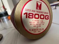
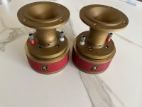
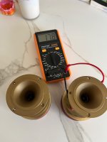
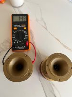
Information outside of Japan is scarce, but I believe these were YL’s TOTL high frequency driver / tweeter. Very rare to find one in working condition, let alone a pair.
$2,000 net to me, shipping only in the USA for now.
Found the site through a few random searches and there were some great threads I still have some questions on.
Large fan of 80s-90's rock and have been known to cycle through hardware on a personal quest for things I think sound better.
Looking forward to reading up on other peoples projects and trials with varied hardware.