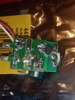
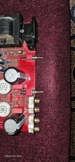
Vintage board UAP-02 - RCA 70 Watts - Temperature problems

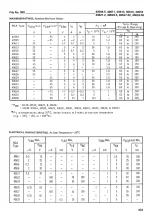
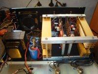
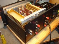
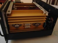
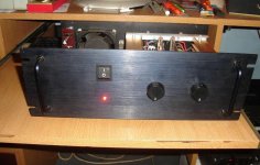
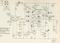
This is a request for help to the older ones here ( me too 😉 ) twho surely knew the RCA power amp based on the UAP-02 board. I'm talking about the 70's. I built the 70 Watt version of this amplifier back then, and every now and then I used it, normally I used it with my PC to feed two small speakers, so it was never used intensively or at high volumes. But, (there's always a first time) lately the left channel started to heat up so I decided to put the noble NAD 3020 in its place, and decided to see what was causing the overheating. I proceeded to check DC voltages at the output (Offset), 1.0 mV on the left channel and 9.0 mV on the right, which I considered acceptable, so the next step was to check the quiescent currents (Bias). As it was recommended in the days of analog multimeters, I did not use the typical procedure of inserting the ammeter in the collector junction of the output TRs with the + B, because the internal impedance of the same would slightly alter the measurement and this method forces us from physically opening the circuit. (Although I remember having done it on DIY - Phillips boards without problems - I do not know if using a digital multimeter the same thing happens) Applying Ohm's Law, in theory the Bias of the left channel was 41.5 mA, and of the right channel 45.9 mA, which caught my attention, I expected that the one that exceeded the maximum recommended by RCA (40 mA) was the channel that was heating up, the left one, but it is the other way around.
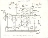
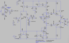
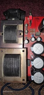
That said, I proceeded to adjust the presets of both channels. (RCA recommended installing a 100 Ohm preset instead of R11 in case of temperature problems.) and I managed to adjust both channels as you can see:
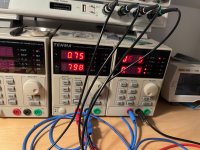
+B 39.5 Volts DC / 117.5 Ohms = 33.6 mA.
I was surprised that the preset allowed me to exceed the maximum 100 Ohms, but I suppose that the manufacturing tolerances in those years were quite large.
But, I was greatly surprised to find that after these adjustments, BOTH channels overheated much more, evenly and gradually, and in a few minutes!
With an ambient temperature of 27 ° C, in 10 minutes the heat sinks reached 45 ° C! The amplifier works well, and the offset now, with this temperature, is 8 mV on the right channel and 0.7 mV on the left channel.....At this point, I turn off the amplifier, the 40636 output from RCA indicates maximum 200 °C, but I won't wait to spoil them, this operation is not normal...
I really can't figure out why this can happen, I thought that some TR - input differential pair - could have become unbalanced, which usually causes anomalies in the DC output, but, that failure in both channels simultaneously? And also the DC at the speaker output is not so high...
Should I go back to the traditional Bias adjustment?
What have I forgotten in all these years ?
I will appreciate any thoughts that help !

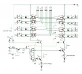
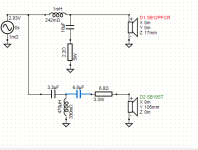
PS: The diagrams are taken from the web, the notes and measurements do not correspond to my amplifier. I will look for the original diagram and upload it, although being in red I fear that it is not very visible.

Attachments

  • 2-bb163c3178.webp
    2-bb163c3178.webp
    96.5 KB · Views: 126
  • Instalación fuente y Led - Potencia RCA 007.jpg
    Instalación fuente y Led - Potencia RCA 007.jpg
    96.6 KB · Views: 90
  • Instalación fuente y Led - Potencia RCA 032.jpg
    Instalación fuente y Led - Potencia RCA 032.jpg
    108.3 KB · Views: 91
  • Instalación fuente y Led - Potencia RCA 037.jpg
    Instalación fuente y Led - Potencia RCA 037.jpg
    107.9 KB · Views: 93
  • Potencia RCA 031.jpg
    Potencia RCA 031.jpg
    68.8 KB · Views: 97
  • Instalación fuente y Led - Potencia RCA 017.jpg
    Instalación fuente y Led - Potencia RCA 017.jpg
    135.7 KB · Views: 113
  • amp6.jpg
    amp6.jpg
    91.3 KB · Views: 132
  • circuito.jpg
    circuito.jpg
    479.6 KB · Views: 130

Conrad Johnson PV10A voltages

So I gave Conrad Johnson a call in regards to the voltages at certain points in the schematic. They don't offer these on the schematic because they do in-house servicing for customers. However at $150 an hour my PV10A is never going to get there especially because I fix all my own stuff.

My system has an over voltage issue which results in the NPN transistor in the primary power supply shorting collector to emitter. They read somewhere in the neighborhood of 360 volts.

I was hoping if somebody here has a PV-10A, with phono stage, if they could perhaps probe a couple points for me and let me know what their voltage is are. Mainly what I really need is what is the voltage on each of the large 20 UF bulk capacitor after the bridge rectifier.

Also I was hoping that somebody was able to get some voltages for me to find out what the AC output of the transformer is on the high voltage and low voltage test points.

If someone is able to crack theirs open I could take a picture of mine and point to a few other places where I need voltages.

All the components seem, And that is a heavy seem to be spot on. I double checked the transformer primary wiring to make sure I wasn't somehow producing higher secondary voltage.

The smaller filament supply seems to be working perfectly.


I am a newbie in this forum so be gentle.

Thanks for your time if you made it this far!

Dear Sirs/Madams! I salute you

Greatings all!
My name is Jørgen, born and bread in Oslo Norway, pushing 60 and not really a freshman on this glorious site.
However this is my first hello as up to now i have only been present as a bottomfeeder, feasting on your accumulated knowledge to improve my skills and verify the validity of my own projects.
So here i am and ive got a question i am eager to post in the apropriate department.
  • Like
Reactions: grindstone

3116D2 amp and some questions

I just finished my very first amplifier, with schematics based on tpa3116d2 evaluation module (https://www.ti.com/lit/ug/slou336b/slou336b.pdf). The only change I made was to drop the gain to 20dB, and remove some jumpers. I threw together the box from 0.25" oak board pieces. All parts came from digikey, except the power button and connectors that I ordered on aliexpress. The PCB was designed in kicad and manufactured by jlcpcb. This was a very exciting project overall (for me). I still have a few remaining problems and would appreciate some help,

(1) The speakers emit some white noise when there is no input. It is barely audible, but becomes about twice as loud a few seconds after the input stops. Does anyone have an idea on what could be going on? In any case, I can still only hear it if I put my ear next to the speakers.

(2) I would like to have two stereo inputs in it. I was planning to add a mixer. Could someone please suggest a mixer that is decent and not too complicated to understand? I don't have enough experience in audio to design something like that. I did go over the mixer page (https://sound-au.com/articles/audio-mixing.htm) and some opamp theory in Sedra's book.

Thanks All.

Attachments

  • image.jpg
    image.jpg
    798.4 KB · Views: 74

NEW Toshiba 2SJ313 / 2SK2013 Quads (matched)

Hi,
I wont need all my transistors anymore, so i will sell a few quads that are left.
Each quad has 2 x 2SJ313 and 2 x 2SK2013.
I will ask 99€ for a quad.
I prefer shipping within europe, but worldwide is no problem (only fully insured), with tracking.
Inside europe shippingcosts are around 19€.
Paypal as friend.
Pictures can be added.

Regards
Alex

Waveguide for BG Neo3 PDR - in 3-way (8"+4,5"+BG)

I searched... one forum, another, google images, but I didn't find any WG files for B&G NEO3 PDR.

They will be connected with Seas MCA12RC. The front panel will be straight, but with bevels like AVALON. However, I need to get an offset and the original frontplate does not allow it.

Could someone help me?

Attachments

  • IMG-20240601-WA0002.jpg
    IMG-20240601-WA0002.jpg
    255.9 KB · Views: 66

Thermostat relay causes computer monitors to restart

Merry Christmas everyone!

I have noticed that the central heating thermostats are causing my monitors to restart. Immediately after the thermostat clicks, the monitors go black and restart a second later. I suspect this is caused by the back EMF generated by switching inductive solenoid.

I thought of adding some sort of snubber, maybe just a capacitor in parallel with the relay switch. However, I am not sure how much I will violate safety (and regulations).

Does anyone have any idea if this is a good idea? Or is there a better solution?

For more information I have attached the photos of the unit.

Attachments

  • IMG_5170.jpeg
    IMG_5170.jpeg
    582.9 KB · Views: 47
  • IMG_5171.jpeg
    IMG_5171.jpeg
    481.6 KB · Views: 46

Problem powering up first amp - any hints welcome

Hi all,

Since a few weeks I have been busy prototyping my first power amplifier based on Douglas Self's Blameless design.
I attached the LTspice file that reflects the actual circuit (except for one of the resistors in the Vbe multiplier, because the simulation with the actual value gave a slightly too high bias voltage, whereas reality is okay).


As a first test I used a small-signal (full voltage swing, constant-current, few milli-amps) class-A output stage. This worked fine. I was able to verify the correct working of the input stage and VAS using this output stage: grounding the input resulted in near-zero volt output without dc-offset trimming, and a sine input of a few hundred millivolts gave a (relatively) clean sine output of several volts.

Currents sourced in the stages were approximately as I expected, and the voltages at various points are okay.

Then I decided to try the actual class B output stage, without any load. With great anticipation, hoping to see a nice zero volt output with grounded input, I switched on my lab supply. And got a clipping amplifier, with huge current running in the output stage.

For some time now I cannot figure out what is going on, and do not know how to continue from here.

I have restricted the lab supply to different currents to see the effect of that, but mostly around 800 milli amps. This to prevent destruction of the output devices. The side effect of this is of course that the voltage rails collapse, which I think results in misbehaving small-signal stages.

To make sure that all of this was not caused by any Vbe multiplier problem I shorted the multiplier's collector to emitter, effectively removing any biasing. I rather have an amplifier with huge cross-over distortion to start with, than one that's about to apply for a job as smoke generator.

At the moment I'm short of desperate getting this thing working. What joy is awaiting me, when hearing the first tones erupting from the amplifier, after first ensuring a simple grounded input and sine input give the expected result without any load and with an 8 Ohm power resistor.

Does anyone have any clue what could be wrong or how I should proceed?

Attachments

  • actual-circuit-22-nov-2024.png
    actual-circuit-22-nov-2024.png
    68.9 KB · Views: 220
  • actual-circuit-not-working.asc
    actual-circuit-not-working.asc
    23.3 KB · Views: 53
  • breadboard-22-nov-2024.jpg
    breadboard-22-nov-2024.jpg
    694 KB · Views: 231
  • lab-supply-22-nov-2024.jpg
    lab-supply-22-nov-2024.jpg
    509.1 KB · Views: 209

Mini transformer / parts in LED lamp

Wonder what type of mini transformers these are and if they could be used for anything in Hifi alternatively.

Got it out of led lamp.

Nice 400v electrolytic to be found in and can be reused. And the other parts?

Who knows what can be done with it?

IMG_20240105_143012.jpg

Attachments

  • IMG_20240105_143058.jpg
    IMG_20240105_143058.jpg
    377.7 KB · Views: 138
  • IMG_20240105_143052.jpg
    IMG_20240105_143052.jpg
    479 KB · Views: 149
  • IMG_20240105_143034.jpg
    IMG_20240105_143034.jpg
    484.6 KB · Views: 145

Tweeter dust cap glue for KEF Q-series (Uni-Q)

Heel there and very nice Christmas🙂

I'm working over (new ferro fluid) some tweeters from some KEF 65.2 and Q5's. I've cleaned / removed all the old glue on the plastic parts. I need to know what kind of glue I should use to mount the dust cap with coil to the plastic ring. I don't want to use super glue (also not the slow drying ones). Would some tiny bits of bison kit or tix serv the purpose or would I be needing something else?
WhatsApp Image 2024-12-25 at 09.55.52.jpeg

WhatsApp Image 2024-12-25 at 09.56.41.jpeg


thx in advance

willem

Poor Serbian Man Optical Volume Control

here it is ;
result of collaboration of few Serbian DiyAs - one engineer mind (sp300b) and one sick mind (ZM)

as usual - ZM does all back of napkin drawings and some testing , sp300b does some much more testing and pcbs ;

find schematics enclosed ; pcbs are in stage of testing ..... in fact - pcbs for PSM Optical Volume

are ordered , and pcbs for separate buffer are in developing ;

first - PSMLS schematic ; nice drawn by sp300b ( not in my usual gorgeoushandscribing way )

it's intended either for stereo balanced or stereo unbalanced ( omitting
4 LDRs)

Attachments

  • psmlsw.jpg
    psmlsw.jpg
    84.5 KB · Views: 9,974
  • Like
Reactions: weissi

Current feedback amplifier + push-pull cascoded VAS

'Tis for a guitar amp. (I have never designed, nor built a power amp. In the words of Jeremy Clarkson: how hard can it be?).

Specifications:
  • at least 20W@8ohm, <3%
  • soft knee clipping
  • high output impedance (or mixed mode feedback, possibly)
  • use of lateral MOSFETs for ease of biasing ('tis my first amp, after all)
  • no tertiary power supply for the input stage and VAS (for simplicity and to actually keep power levels low)

Power rails would be either +/-35V (ish) or single-supply 70V (ish), which should allow for a 40W-ish clean power (taking the MOSFET drop into account).

My idea:

- use a single-ended input stage employing current feedback (as in the following examples: https://sound-au.com/project217.htm https://sound-au.com/project12.htm either with an output cap, DC adjustment or better yet, a DC servo)

- use a push-pull cascode VAS with dynamic gate bias as in Slone's OptiMOS amp for its soft clipping characteristics (right there in the middle)

1718815699268.jpeg


- with such a VAS, possibly capable of beefier current than the usual, do without MOSFET drivers.

MOSFETs would probably be the Exicon devices (rated 125W).

Could it work? Replicating the OptiMOS design for a guitar amp is extravagantly overkill, and I don't feel I need all the symmetry or complexity. Also, 2nd harmonic distortion is not a big issue. If it's rich in low-order distortion, that's actually the design goal.

No, I don't want to go with a soft clipper (whatever it may be) before the power amp, because the response would be quite different, and most of all, it would be too easy 🤣 . The clipping should be generated internally by the high output impedance power amp with all its interactions with the speaker.

Troubleshooting hum in an Elekit TU-8200

I've got an original Elekit TU-8200 that I built back in 2016. It's developed a hum in the left channel, audible in the speaker as well as headphones. I've swapped the pre-amp and power tubes to no effect. Googling led me here (well, the Elekit forum here, but alas I can't post there yet 🙂, and suggests I need to replace my FET(s).

I've measured the voltages at the documented test points, and several on the left channel are out of spec. Anything else I should check, or just order some FETs and swap them out?

And @vkung if you're watching, I suspect you'd be able to nail this one down quickly.

Thanks!

Voltages (12AU7 and 6L6EH):

1 -> 3.8
2 -> 3.5
3 -> 3.6
4 -> 3.6
5 -> 123
6 -> 119
7 -> 127.1
8 -> 116.1
9 -> 220.2
10 -> 208.9
11 -> 1.1
12 -> 0.58
13 -> -20
14 -> -17.3
15 -> 0.03
16 -> 0
17 -> 0.46
18 -> 0.43
19 -> 285.8
20 -> 271.5
21 -> 285.4
22 -> 318.3
23 -> 291.3
24 -> 279.8
25 -> 287.4
26 -> -33.2
27 -> -34.5
28 -> 5.9
29 -> 6.2

CD versus LP - a comparison of the frequency spectra

Hello

just a quick comparison between a CD (16Bit/44,1KHz-Rip) and a LP (16Bit/48KHz-Rip).
Same song and same audio segment.
First: Audacity > Analyze > Plot Spectrum

CD
CD-Rip-Flac_FQ.jpg
LP
LP-Rip-Flac_FQ.jpg

Second: spec
CD
CD-Rip-Flac_Spectrum.jpg

LP
LP-Rip-Flac_Spectrum.jpg


I am amazed, i had expected a worse quality of the LP.

Thorens TD126 MK III + Ortofon OM20, Pioneer SX 950, ACER D270 for analog ripping.

Happy holidays to you all
  • Like
Reactions: dazcwl

DPLL Settings for DSD256 and 512 from HQPlayer

Hello all. I am planning to upgrade my Buffalo IIISE (9018) DAC, which currently uses a Sonore Audiobyte USB to I2S board that can only handle DSD up to DSD128. My source is a Small Green Computer Sonic Transporter i9 and player is a Sonore Signature Rendu Deluxe. Works great upsampling everything via HQPlayer to DSD128, but I'd like to explore the higher rates.

The new setup will feature the BuffaloIIISE Pro (9028) and a JL Sounds USB to I2S board capable of handling DSD512.

In preparation for the build, I was wondering if anyone who has done such a build could recommend the proper DPLL dip switch settings for the BIIIPro 9028 DAC to give a good lock on DSD256 and DSD512 with no extraneous noise while minimizing jitter. Of course I will do my own experimentation, but having a starting point is always helpful!

Thanks in advance for any advice given!!

fillament hum balancer trimpot

Hi, I plan to use the following transformer setup:

hum_balance_trimpot.jpg
The diagram bellow shows a 'regular' hum balancer wiring.

In this case there must be galvanic connection between the fillament windings and ground.

R-drop resistors are needed to drop from ~9v AC to ~6.3v
R11-12/ 21-22 are chosen 1k so that it has neglibile effect when it shortens the transformer winding (leftmost), and the R-DROP.
There are seporate R-drop and hum balance wiring for two identical tubes - this is for symetrical load distribution between the two transformers.
The HT transformer is connected that way as well - to share load from both primary transformers.

But would it actually work?
As far as I understood, the hum balancer shifts the fillament AC phase, so it kind of cancels out relative to the tubes power supply.
Here the balancer is connected to ground and the fillament potential 'starts' ~3 volts above the ground.
// R-drop should be ~8.1 ohm, R fillament is supposed to be ~18 ohm
There could be other options for wiring, I allready got confused drawing this one 🙂

Next option is regulated DC power supply, so the rectifier kind of 'isolates' the fillament ground from the common ground.
Least favourable is adding seporate heater transformer.
In general I want to keep it as simple as possible with the layout above.

Regards - Emil

Tube Amp One Channel Dropout

I have a Schiit valhalla 2 preamp. It was working quite well till last month, after which it started giving a problem of losing one channel after about an hour of usage. When I turn on the amp, it plays just fine, then after around an hour or so, the left channel starts to distort/crackle and then mutes itself. It then restores itself after about a minute and sometimes it doesnt. I have tried a few ways to debug the issue from Changing to New tubes as well as changing New tube sockets as well as changing to a New potentiometer. But the problem remains. Tried cleaning the input and output rca Jacks as well but to no improvement. If I use a different preamp, everything plays just fine, so no issues with any connected equipment as well.


I suspected a cold solder joint somewhere, but could not really find one upon inspection (but it may be there)

Can a failing coupling capacitor be a suspect ? Tried using a magnifying glass to inspect a cold solder joint but could not find one. Whatever looked dry, i reflowed New solder on them.

Please advise
20240919_150300.jpg
20240919_150300.jpg
20240919_150300.jpg
20240919_150328.jpg
20240919_154556.jpg
20240919_154533.jpg
20240919_150318.jpg
20240919_154556.jpg

Attachments

  • 20240919_150333.jpg
    20240919_150333.jpg
    651 KB · Views: 29
  • 20240919_150308.jpg
    20240919_150308.jpg
    830.4 KB · Views: 33

For Sale Emerald Physics CS2 with miniDSP

For Sale: Emerald Physics CS2 speakers with MINIDSP 2x4

Sold these to a friend years ago and recently traded them back for a Hypex amp.

I have the original CS2 boxes (a bit ratty), but the original Behringer DCX2496 was replaced with a standard MiniDSP 2x4 unit.

The speakers themselves look very clean with zero issues. Pickup in west sub of Chicago only....to big/heavy to ship.

I recently built a "pseudo clone" of these CS2 with the four Eminence 15A Alphas but with Heil AMT tweeters that I am sticking with (builder's bias?).

How's $675 picked up?

I also have a pair of PASCAL stereo amps 500Watt/125Watt (4 channels total that are prefect to biamp these CS2) that can be added to the sale if needed...

Attachments

  • 2.JPG
    2.JPG
    367 KB · Views: 204
  • 6.JPG
    6.JPG
    350.9 KB · Views: 210
  • 3.JPG
    3.JPG
    384.6 KB · Views: 214

LM1875 minimal gain

Hi, LM1875 circuit:

IMG_20241224_122206_988_LL.jpg

The 1k/ 330p network is a low pass 482kHz I guess. Is it a good idea to tweak it to around 10kHz?

The datasheet states that the chip is stable at gain >= 10.
Is it ok to lower it to 6 or 4?
The preamp levels are high and I don't need gain of 10.

The circuit is intended to work in the range 2k5 - 10k. A HF driver for a bass guitar cabinet, 2k5 active crossover before the amp.
I want to minimize all hearable HF noise, introducing LPF and reducing the gain.
  • Like
Reactions: lineup

Which cartridge? Denon DL 103 or Ortofon 2M Black?

I'm looking for either....

A new stylus for my current Ortofon 2M Bronze. (The Black stylus fits),

A new Denon DL 103,

Or I've just see a Denon DL 103R for a similar price.

Turntable is a Project 1 Xpression with carbon arm and my phono stage is a Cambridge Audio Alva Duo so MM/MC.

I know carts have been covered lots but I just want to know if there's anything else I should be looking at for around £450? Or if not, what would be the best of the 3 I've mentioned.

Any advice appreciated.. And Merry Christmas!

Finding Q-factor by graphical method

I’ve been attempting to formulate an empirical formula for finding Q-factor of second-order filter by using graphical method. Say we could find Q-value from the frequency response curve. And, finally, I obtained it, that is, Q = 10^(x/20) where x is the -dB at Fb (box resonance). I verified with theory and many examples and it worked.

For example,
if x = -3dB, it yielded Q = 0.707 or Butterworth slope
If x = -4.5dB, it yielded Q = 0.58 or Bessel slope
If x = -6dB, it yielded Q = 0.5 or Linkwitz-Riley slope
Etc.

Nonetheless, that formula can only be used for Q of enclosure. It wouldn’t work for electrical fIlter because I cannot find the corner frequency on the amplitude curve. So anyone advise me how to find corner frequency from the frequency response graph? Don’t suggest me to look at -3dB point because it would be correct only for Butterworth filter.

Hi from Paris, France

Hi,

I am from France. I am in my fifties and was really passionate about electronics as a teenager. I missed the opportunity to work in this field for various reasons and did not pursue it even as a hobby. But....

I recently bought a Meridian 557 amplifier and decided to recap it myself. This may be the first of a new long list!

Thierry
  • Like
Reactions: Vix and druidaudio

Threshold FET 2

Over the weekend i came across an old FET 2 preamp in slight need of attention (blown MC input, malfunctioning muting relay).

This was hardly a statement product in its heyday but the quality of case, pcb and layout really impressed me. The sound also exceeded my expectations.

Fwiw, i think that it would make an excellent simple project for anyone wishing to build a nice sounding discrete preamp. I am fairly certain that its phono section is better than any of the el-cheapo, single opamp designs.

So, this morning i attempted drawing the circuit. Although trying to be careful, i may have made an error or two, so if anyone spots anything funny please let me know.

The preamp has a separate MC gain stage which, being a common gate circuit is rather unusual. It uses a parallel 2N5566 and i found that a 2SK389 works quite well. The trimpot is used to set 0v at the input which seems to be quite reliable and stable.


Predictaby, this is the worst sounding part of the unit. Most probably because of the PS - remember this pre is built for a limited budget. Entire pre is supplied from a nice but tiny 30VA 2x20v toroid followed by a bridge, 2x2000uF Mallories and separate 7824,7924 for each channel. No local regulation, just single caps per rail near the line amp (no markings, must be around 100uF)

IME a MC gain stage requires the absolute best PS with batteries or dedicated Jung type regulator to sound acceptable.
Coupling cap to MM stage is a 1uF polyester-looking Electrocube.

R1 is selectable for 3 values - 50, 100, 200 ohm.

Attachments

Calculation for third-order crossover

I've been wondering how to calculate crossover frequency of the third-order crossover and its parameters from the schematic.

Let us consider second-order crossover, there are two formulas to calculate the parameters of the crossover which are crossover frequency and quality factor. The crossover frequency of the second-order filter is calculated from resonance formula: f = 1/(2 x pi x sqrt(L x C)) and the quality factor is calculated by Q = sqrt(CR^2/L).

But, how about third-order system? Are there formulas for calculating crossover point and Q-factor as the second-order system?

I know the simulator software can do it very well. But sometimes it should be more handy with hand calculation.

Assume we have a series 6.8uF capacitor and a shunt 0.2mH inductor, we can easily obtain crossover frequency and Q-factor of this second-order filter by using two formulas above. What if we add a second series capacitor of about 18uF to it, now the crossover is converted to be third-order system, can we find crossover frequency and Q-factor (if any) of this third-order filter?

ASTX AudioLabs 4x SA2015 V-Mos (my personal build)

Hi all 🙂
After successfully completing excellent SA2014 from @astx , I decided to build the SA2015 V-Mosfet (4x SA2015 in one box). I want to build this amplifier for Bi-Amp wiring and compare with single amp wiring (SA2014).

This 4x SA2015 V-Mos will be housed in a single 5U/400mm box from modushop. The feeding of these 4 modules will be handled by 2 massive 500VA toroidal transformers from Toroidy_pl. Each module will have a separate power supply (4x 15.000 uF Nichicon).

Original thread ASTX: https://www.diyaudio.com/community/...ance-class-ab-power-amp-200w8r-400w4r.235194/

SA2015, PSU , transistors --- (all from astx)
IMG_20241108_132631.jpg

Softstart (incl DC protect)
softstart.jpg

SSR3 speaker protect
ssr_preview.jpg

If anyone would also like these protections they can join the ongoing GB.

Ground Loop
ground loop.jpg

* All input and output connectors will be of premium quality as well as the internal cabling, ...probably from SUPRA.
  • Like
Reactions: astx

NAD T748 input problem

Hello.
NAD T748 V1
Works fine, just one problem.
Analog Source one......no sound.
All auther sources works fine but the sound appears only after 10 seconds

That is, if I select an input, it appears on the display but the sound will only appear after 10 seconds. There is never any sound at analog input number 1.

Factory reset doesn't help.
Last firmware is installed.

Thanks


Service manual

https://acrobat.adobe.com/id/urn:aaid:sc:EU:7d422752-fb6b-45b5-aaa3-3ae30999865c

Greetings from Ukraine (khm region)

Good evening, everybody! I’m from western Ukraine, city Khmel’nytskyi. It’s my new account, because old one (viking_km) is deactivated since I didn’t used it for a while and it was registered using ruzzian email a long time ago. Now I’m here because my interest to build devices with good sound has been reopened again 🙂. Right now I want to build a tube RIAA phono stage and buy some vinyl turntable

Hello from California

I guess you'd say my hi fi tastes are high-middle-brow: bought my first AR speakers, Marantz amp and Shure V15 in about 1972. I have mostly Yamaha electronics now, though I'm no longer much of a fan of the variable loudness control that led me to Yamaha originally (I think it is really a variable high filter). Still like AR speakers but I've picked up JBL's and Bose and Klipsch over the years. I found this site by looking for a particular topic of how stylus force deforms a vinyl record.

TU -8200 check voltage

Hello everyone,
a few years ago I bought my Elekit TU-8200 which I built myself.
Now I would like to check all the voltages as suggested in the manual but it seems to be quite difficult as the components are mounted upside down on the board ....
Is there someone on the forum who has already marked all the control points on the welding side who wants to share his experience, in order to help even inexperienced people like me ... ????
Photos would be appreciated
Thank you in advance 🙂

Show us your DIY coaxial drive units

This was asked for in another thread, so I thought I'd start it here, though it was not asked of me.

I have only really assembled one pair, which I dubbed the "Foster-Franken-Coax". This used 12" Foster woofers and 1.5" Foster dome tweeters, both from a pair of Sears-branded speakers.

07-jpg.648671


I have no data or measurements, this was before I got more serious into the hobby.

The tweeter was held in place via a short length of ABS pipe, glued with epoxy to both the pole-piece and tweeter back-plate. The tweeter leads were made with solder wick going through the cone, where I made a small slit and sealed it back with glue. I briefly tried these in a Karlson 12" box, where they performed horribly, way to small Vb for the woofers. I then stuck them in a large-ish sealed box and gave them away to a buddy who I haven't heard much from in a long time. That was about 10-12 years ago.

Now, those who have handled these tweeters know they are fairly massive. I can't help but imagine that since then, the glue must have failed or is about to. Whether this happens at the pole-piece or tweeter back plate, it will brutally and irreparably take out either if not both the woofer cone and voice coil. I should check up on said buddy and see if these have met an horrible demise or if I have underestimated the strength of Lepage 20 minute epoxy.

What are your experiences with DIY coaxial drive units?
  • Like
Reactions: HEXAAA and krivium

XMOS I2S periodic audio pops in Windows / not in Linux

Hi,

I use a chinese XMOS I2S interface board (Crystal upgrade XMOS XU208 DAC + cpld card USB digital interface I2S DSD output for AK4497 ES9018 ES9028 ES9038 decoder E4 007-in Amplifier from Consumer Electronics on AliExpress) with a chinese ES9038 board (ES9038 Q2M DAC DSD Decoder Support IIS DSD 384KHz Coaxial Fiber DOP | eBay).

Several different drivers were tested, they all produce the same issue: I get periodic audio pops (buffer overflow/underrun? Recording+its spectrum in attachments) every few seconds. This does not happen when I feed S/PDIF directly from the PC to the DAC.

I've done a quick test playing back a 400Hz test signal via foobar (happens everywhere - videos, browser, games) and depending on the sample rate these pops appeared in different intervals:

44100 Hz: every 88s
48000 Hz: every 95s
88200 Hz: every 44s
96000 Hz: every 44s
176400 Hz: every 22s
192000 Hz: every 25s

I've tried the same USB interface / DAC combination on three different Windows-PCs (all Windows 10), they all show the same result. Then I tried installing a fresh version of Ubuntu, didn't change any driver related settings, and there are no pops at all with the standard alsa drivers on any sample rate. Since the DAC itself doesn't "see" the OS, I guess it's not a DAC issue.

Apparently this XMOS device doesn't work properly under Windows 10. Did anyone experience something similar with these devices? Could this be a firmware related issue which can be solved by flashing the firmware?

Are I2SoverUSB, diyinhk and WaveIO still recommended USB/I2S interfaces? In case I find no fix I'd buy a new interface and would much rather have existing customer support this time.

Attachments

  • pop.jpg
    pop.jpg
    199.6 KB · Views: 183
  • pop.zip
    pop.zip
    63 KB · Views: 79

FH3-inspired Foam Core Mini Build

FH3-inspired Foam Core Mini Build HOWTO

I've gotten some requests to provide details of how to build the FH3-inspired mini speaker in foam core and thought that a new thread with the "how to" might be useful.

If you have been following the Foam Core or Cornu Spiral threads (http://www.diyaudio.com/forums/full-range/223313-foam-core-board-speaker-enclosures.html and http://www.diyaudio.com/forums/full-range/225622-ever-think-building-cornu-spiral-horn-now-you-can.html), this will be familiar. I recently built a smaller all foam core speaker inspired by the very elegant FH3 to see what it sounds like without having to cut any wood or having to invest too much time in the shop (if I had one). Being made of foam core boards from the dollar store, the maximum dimension would be 30 inches. I also wanted to use a smaller less expensive driver to match the smaller cabinet and to save money. Having my favorite budget Vifa TC9FD driver (Vifa TC9FD-18-08 3-1/2" Full Range Paper Cone Woofer 264-1062) on hand, I set out to design the new mini FH3-inspired speaker by scaling the cross sectional areas of the speaker's horn as a function of the driver piston area Sd. My calculations showed that the FH3 has nominal cross sections of 2x Sd at the folding point, 4x Sd at the base, and 1.06 x Sd at the terminus choke point. These were calculated from the published dimensions of the FH3 (http://www.google.com/url?sa=t&rct=j&q=frugel%20horn%20mk3%20plans&source=web&cd=9&cad=rja&ved=0CGMQFjAI&url=http%3A%2F%2Fwww.p10hifi.net%2FFH%2Fdownloads%2Ffrugel-hornMk3-1v0-250212.pdf&ei=h8TuUNO5K4W80QGh2YD4AQ&usg=AFQjCNFRzgZK1QjpBt2V3mP5wK3U97zfUw&bvm=bv.1357700187,d.dmg)and one of the recommended drivers - the MA CHR70. Armed with this knowledge and constrained by a maximum height of 30 inches, and knowing that the cabinet needs to be at least 4.5 in wide for the baffle to properly mount the Vifa, it was a simple matter to derive the cross sections at the fold point, the base, and the terminus for the Vifa driver.

The resulting principal dimensions that came out of the scaling were surprisingly even and simple: 2.5 inches x 2.5 inches x 2.5 inches at the fold point for a base depth of 5.0 inches, and a terminus gap height of 1.33 inches. The cabinet is sloped back at an approximate 5 deg angle to form a parallelogram when viewed from the side. Rather than deal with angles, I measured a setback of 2.5 inches from vertical to approximate the angle. Thus will also require the height of cabinet (vertical) to be only 29.9 inches in order to preserve the 30 in length for the baffle. So we now have a very slender looking cabinet that is 4.5 in wide x 5.0 deep x 29.9 in tall. Such a cabinet would not be very stable and tip over easily requiring outrigger feet for stability. Foam core construction permits the neat ability to make compound or complex curved walls at will. Thus I decided to curve the rear horn walls outwards to give the base stability and provide more expansion for the rear facing horn mouth. So I expanded the rear mouth from 4.5 in to 12 inches over a distance of 10 inches.

Before actually putting razor to foam, I simulated the response in HornResp just to make sure the bass output was reasonable and to see where the tuning frequency was. It looked ok, with a main low bass peak at about 70 Hz and a dip around the 125 Hz region which is OK because that is the Fs of the Vifa and there should be enough output from the driver to fill in. diyAudio

The build went very smoothly, one just has to use a good straight edge (I used a masonite panel) and a sharp razor. Make sure you account for the thickness of the board (3/16 in) as the dimensions above are internal dimensions. Draw the plan on one of the sides and begin by hot melt gluing the back panel. Use a square piece of foam core as a gage to ensure 90 deg angle while the glue sets. Then glue on the internal angled divider. Also use the 90 deg gage to ensure squareness. It helps to glue in sections at a time as 30 inches is too long of a stretch to do in a single stroke with hot melt. Then glue the front baffle, which I made wide to cover the front joints. It is trickier than the back or divider to glue as it is not lying directly on top of side. You can make construction easier by gluing it on the side just like the back if you make the sides deeper by 3/16 in to accommodate the thickness. Then bracing needs to be added, I had 3 major brace locations. These are cut to fit and jammed in place with hot melt taking care not to distort the squareness of the cabinet. I also added some front brace strips to serve as ledges for the final side to be glued on. I also added a second 4.5 x 4.5 in piece of foam behind driver for a double layer to give more support for the driver mounting.

Then a curved piece needs to be glued over the terminus to provide a smooth flow at the mouth. Curves are made by scoring lines deep enough just to pierce the paper on the concave side to allow the foam to compress when you bend it.

Next comes mounting the binding posts and adding wire to receive the driver once it is all buttoned up. I hot melted the binding posts onto the back and added crimped wire connectors with wiring for the drivers.

Now comes the dampening plan, I used the suggestions from the FH3 plans and added pillow stuffing into the closed end and used open cell foam to line the walls adjacent to the driver, ideally felt should be used. The top is left off for adjusting stuffing after build is complete. Now the second side panel is glued on with pva glue and a combination of hot melt at stragegic points to act as a tack while pva dries. I used books and dumbbells to clamp the side. Rubber bands can also be used to apply tension to clamp baffle edge to side as side is not on top of baffle.

Once the side gluing is complete, check for any leaks or gaps and fill in with more pva or run hot melt glue over gap to seal. Now the base is glued on with hot melt. Do the straight sections where the main box is first, then glue the curved sections in bits at a time while bending the horn mouth outwards like a wing. Hold in place with your hand while hot melt glue sets. It makes a nice graceful curve which now doubles as support feet.

Finally, cut the hole for the driver - use a template and center it at 2.5 inches down from the top. Glue small strips of wood where the screws go to provide purchase for the wood screw threads. Install the driver and now add stuffing to cavity behind driver and maybe 2 inches below driver but no more as that will kill bass extension. Use a temporary means to fasten top on and listen to speaker, and adjust stuffing as needed to taste. I used quite a dense pack behind driver to absorb reflections that could go back out the cone. Once you are satisfied with sound, hot melt glue the top on and you are done.

How does it sound? Fantastic! There is plenty of warm deep punchy bass emanating from the terminus. The Vifa does a great job with the mids and highs. The sound stage and imaging are superb. The sound stage does not feel as wide as the Cornu but that is to be expected as it is not 24 or 28 inches wide. I like how the bass and mid bass sound more balanced than Cornu, but overall, the Cornu's wide sound stage and impressive mid bass still manages to knock my socks off. The foam core FH3-inspired speaker definitely is one of my favorites and I understand its popularity: not only does it sound great, it looks really nice. I like how it sounds so much that I started on the build of the second channel and promptly ordered more Vifa drivers as I am borrowing the ones from the Cornu spiral.

Each speaker uses about 3.5 sheets of foam core board. The total cost of each speaker is under $20 including driver, binding posts, foam core, and glue. The build time (not including glue drying time) is about 3 hours per speaker. The second one goes faster due to the learning curve.

Give it a try, it is a lot of fun, they sound great, and look even better. 😀

these designs are NOT in any way approved, endorsed, or connected to the real frugal-horn.com Frugel-Horn designed/developed by Scott Dave, Chris.

Attachments

  • Foam-FH3-layout-960557547.jpg
    Foam-FH3-layout-960557547.jpg
    115.4 KB · Views: 4,055
  • Foam-FH3-build-bracing1670431727.jpg
    Foam-FH3-build-bracing1670431727.jpg
    125.9 KB · Views: 3,966
  • Foam-FH3-damping11648466299.jpg
    Foam-FH3-damping11648466299.jpg
    155.7 KB · Views: 3,944
  • Foam-FH3-terminus-detail-1141689260.jpg
    Foam-FH3-terminus-detail-1141689260.jpg
    98.4 KB · Views: 3,895
  • Foam-FH3-build-09-1067673785.jpg
    Foam-FH3-build-09-1067673785.jpg
    130 KB · Views: 4,136
  • Foam-FH3-build-11-1712313160.jpg
    Foam-FH3-build-11-1712313160.jpg
    126.3 KB · Views: 1,278
  • Foam-FH3-build-101105487053.jpg
    Foam-FH3-build-101105487053.jpg
    99.6 KB · Views: 1,029
  • Foam-FH3-build-12803233267.jpg
    Foam-FH3-build-12803233267.jpg
    126.9 KB · Views: 1,141
  • Foam-FH3-build-finished2-779268845.jpg
    Foam-FH3-build-finished2-779268845.jpg
    91.9 KB · Views: 1,204
  • Foam-FH3-build-finished4-222524412.jpg
    Foam-FH3-build-finished4-222524412.jpg
    133.5 KB · Views: 1,425
  • Thank You
Reactions: Elias Zacharopoulos

2V, 2.5V, and 4.5V Line Levels? What are they?

Probably a trivial question, but it seems odd to me. In datasheets and other sources, it states that line levels are either 2Vpp or 2.5Vpp for consumer, and 4.5Vpp for professional line levels. The standards state consumer levels as 894mVpp (-7.78dBu) and professional as 3.472Vpp (+4dbu). There's also a "standard" called "semi-pro" that seems to be anything in between.

Maybe those non-standard standards where devised to prevent clipping and where intended for inputs only? If so, using those levels as outputs, as they often are, defeats that purpose.

Other than the ARD standard (4.384Vpp/6dBu) which appears to be strictly adhered to, there are some insane nameless standards for some power amplifier inputs, ranging from 5.515Vpp (8dBu) to 34.732Vpp (24dBu)!

Can anyone enlighten me?

Sterling Silver Iris worth buying?

Hi,

I have an option to buy a pair of secondhand Hawthorne Sterling Silver Iris speakers. To me, the treble looks very rolled off and I read mixed reviews on the web.

Should I proceed with the purchase or will I be disappointed?

I've often considered OB's but the cost including shipping to the bottom of the world is large so this pair of SSI's is my only practial option to owning OB's.

Thanks for any comments
Andrew

NAD C542 CD player Technical help needed

I have an older model NAD C542 that I have changed the optics/ribbon cable and it's back working again. The issue I am seeing is that the temps on the caps and I believe transistors are running at temps over 125*F. I believe they are part of the PS? Is this normal when a disc is being played? Perhaps I should change out these caps and transistors? Any help would be appreciated! Thanks 🙂

MACKIE PPM series 808M Amplifier Service

I'm servicing a MACKIE PPM 808M that channel 1 doesn't work but channel 2 is just fine. I've determined the input op amp (U3A - NJM4560M), is bad. This is the input op to the power amp board from the mixer board. Of course the part is obsolete. Anyone have any recommendation on which of the following similar parts I should use as a replacement?

NJM4565M
NJM4580M
TLC272BCPS

Also, how important would it be to replace the good NJM4560M input op amp on channel #2 with the same new op amp part number that I'm using in channel #1?

Hi from the Netherlands

Hello all,

I'm not much of a DIY person when it comes to audio (or anything else in fact) but do have a love for music, mainly jazz and a sizeable vinyl and cd collection. Have always been listening to solid state, except for a little Musical Fidelity tube box that is now idle. But I have always been interested to learn about the magic of tube amplifiers. I have recently pulled the plug an bought a DIY amplifier from the Dutch version of Craigslist. Now in need of some advice on how to connect everything as it came without cables.

The gear in use right now: Linn LP12 or Rega P25 => Audio Analogue Bellini => Musical Fidelity P270 => Jamo Concert 5. I still have some other gear, part of it set up at my girlfriend's house.

Vincent
  • Like
Reactions: freebee

Corona: An Ultra-Low Distortion A2 DHT SE Amp Prototype

...and in addition to being ultra-low distortion, it is low cost as well. The idea was to use high-impedance DHTs that you can pick up for significantly less $ than the good low-impedance triodes, and a cheap input tube. I also used an inexpensive Edcor 5k:8 25W SE transformer. Nothing exotic.

I ran 520V for B+ and 100mA quiescent current, which gave about 19W output at onset of clipping (still 0.3% distortion, but rising very steeply after 19W).

My output tube is an 826, a 60W high impedance transmitting triode, but this approach works well with pentode output stages as well. I actually started this design with 811A in mind. Whatever it was it needed a thoriated tungsten filament, that's for sure. If I had it to do over again, I wouldn't use the 826. Too many NOS tubes are gassy, and without getter material on the inside of the glass you have no visual clues that you are buying a bottle of air. I had a very high rate of returns when purchasing my small stock.

Why call it Corona? Well, the output tube plate, when viewed from above reminds me of the sun's corona. That and the virus by the same name gave me a lot of extra time to work on this.

I'll follow up with posts on theory of operation and detailed performance tests, but here's the simplified schematic and a photo of the amplifier itself to start.
  • Like
Reactions: toshiba_nz

Greetings, from sunny southern California

I'm a new member to the DIYAUDIO family. A little about myself, I'm located in southern California and have built many DIY kits over the years. Cabinets from Jeff Bagby all the way to some big Troels Designs. Just recently finished the DTQWT 212 MK III built from all 24MM thick baltic birch plywood. Those cabinets were insanely sturdy.

Attachments

  • BalticTroels.jpg
    BalticTroels.jpg
    427.3 KB · Views: 29
  • CandyRed.jpg
    CandyRed.jpg
    515 KB · Views: 31
  • SantosRosewoodKairos.JPG
    SantosRosewoodKairos.JPG
    48.4 KB · Views: 25

HELLO DA WORLD

Hello DIYAudio Community,

I’m excited to join this vibrant community of audio enthusiasts! My name is Ali, and I’ve always had a passion for vintage high-quality sound systems. I am particularly interested in audio restoration, as I am currently working on a project related to it.

I’m looking forward to learning from all of you, sharing my own experiences, and contributing to the discussions. Thank you for letting me here, and I can’t wait to dive into the world of DIY audio with you all!

Ali
  • Like
Reactions: Pano

Hello

Hi. I joined this forum a while back to learn and research but I am finally getting around to designing and building my truck audio system. I have a 1981 Chevy pickup with very little space but I want really high quality sound. Many years ago I had a 91 Mazda MX6 and I designed the sound system so that I could turn the volume really low or really high and it would always sound the same and it did not hurt at any volumn. I like to be able to hear everything and have it really loud sometimes. I love almost all types of music except I don’t get jazz, opera, or really heavy thrasher metal, sorry. That is what interests me.

Power supply issues?

New here....having channel/power supply issues with amp and/or graphic EQ. Hoping to gain some knowledge and suggestions to correct the issues. I regularly loose left channel....if I partially unplug the EQ (Pioneer SQ-550) to a half-way loose-ish insertion I can regain stereo. First guess is bad power cord, but I'm no expert. Looking for other thoughts, recommendations and/or actions to take to correct the issue.

Hello

Hello,

I am a new member of this forum. I come from midwest United States. I've been interested in electronics since grade school. I've worked as electronics technician since mid 1980's. I'm pretty much retired now but still tinker around with miscellaneous projects. I've just recently become interested in audio electronics.

Hi from St. George Utah in the US.

I am a career electrical engineer in the area of medical instrumentation and imaging system design. I have retired and now have time to put my electronics lab back together and spend some quality time with electronics. I have always had a passion for audio amplifiers, through Heath Kits I built at an early age. and have decided to take on designing an audio power amplifier for use at home. I have been reading as much as I can, simulating various designs and look forward to interacting with members in diyAudio on questions I have.

Hi from Thueringia

Greetings to the Forum.
My name is Michael, I am from Arnstadt, Germany.
Working as technician in semiconductor industries as reliability engineer.

20 -10 years ago i was interested in car audio an hab build some systems into my cars. After some years of nothing i had started to build "quick and dirty" a 2-Way aktive Speaker System from some leftovers that a had found in the cellar.

PXL_20241223_110900587.jpg
PXL_20230827_083041933.jpg


My interrests are in building LS-Systems and new to me electronics like amps and pre amps.

New rig owner from SW UK

Hello! I am currently building a soundsystem in the southwest of the UK, we have small beginnings but I am building towards a system with XOC TH18 subs, cubo 15 kicks, and MT121 mid tops to play a mix of genres, but mostly tekno, jungle and dub. I am also a DJ and producer so owning a soundsystem has been a goal of mine for a while now. I am new to all of this, having only started a few weeks ago but have been a lurker here for a while, looking to use this great community as a way to gain more knowledge and know-how from more experienced people.

Cheers!
Marley

Kenwood Basic M2 repair and restoration.

New to this group, obviously. How I got here? ChatGPT. Why I'm here? I purchased a Kenwood Basic M2 in Japan in the early 80s to drive my Sansui PM-C200s (only released in Japan). Long and short of it is, sometime in the late 80s I shorted a speaker output, damaging the Sanken DAT transistor for that channel. I had it repaired at a stereo shop and it worked flawlessly for another 10 years before it happened again! At that point the entire setup went into the attic. Fast forward, my daughter developed an affinity for vinyl. We began buying old vinyl together at sales, used stuff stores, etc. Now I need something to play them on. So I pulled the old setup out of the attic, including my JVC QL-Y66F turntable. Now I need to repair my M2. I do have a smaller Kenwood amp in the interim but it does not compare to the M2. So the obvious question is... Is there an alternative to sourcing Sanken DAT1521N and DAT1521P transistors besides used on eBay? I know the drill. They were a specialty product produced for Kenwood and only used in the Basic M2 and Basic M2a. They have been out of production for decades and no data sheet was ever published. I am adamant about repairing this beast. Any insight is welcomed.

Which Pairs to Twist?

I am going to use a couple of 266N12 Hammond transformers to power some Rod Coleman Raw DC modules (for his V-9 DC modules). If I want to twist the secondary leads to minimize hum, I think I want to twist the Blue with the Red and the Grey with the Yellow. Does this seem correct to minimize hum from the wire pairs? I want the parallel configuration.
Thanks
Dave
Screenshot 2024-12-22 154709.png

Attachments

Is a full range 2 way MEH possible?

I’ve seen more than one person assert that you don’t need expensive drivers to make a really good MEH. I have no reason to doubt that, but what if you wanted to simplify things by just making a 2 way MEH, but you also wanted it to be full range ie no subs required. There is at least one mid/ woofer which seems not only capable of covering say 30hz to 1000hz but of doing so with exceptional performance. I am of course talking about what may be the best driver yet produced, the Purifi 10”. Yes its expensive, but I’m wondering if you could make a really great sounding full range MEH with just one Purifi 10” + CD per channel and hence save on buying multiple other mids and woofers ?

There are plenty of experienced MEH builders of this parish and I’d love to hear their thoughts on this.

First Design - SB12PFCR25-4 + SB19ST-C000-4

Hi everyone, I want to share and hopefully get some inputs/feedback on my first two-way design. Please feel free to give any notes/pointers on what I missed.

Background
I've been lurking this forum for years and has been fascinated by the design work of all the people here but never pulled the trigger on doing a build.
And now it's the start of a new year, I decided it's time to try and do a project.

I've set a few priorities for this project:
  1. 2-way design - I looked at this project as a learning experience and I think that I would miss out on the crossover design aspect if I were to do a full-range (which I believe is a very good choice for a first build for most people)
  2. Ported enclosure - similar to 1st point.
  3. Low cost - Since this is a first project, I don't want to spend big, but I also don't want it to be a very low quality build.
As for measurement, I know that a lot of people think that doing a design without measurement is only a waste of time (which I understand) but for this "kickstarter" project, I decided to hold off on purchasing measurement gears as the next step in my journey, just to have something to listen to at the end of the day.

Driver Selection
As for the drivers, the main considerations are availability and cost. Due to the fact that I live in the country where SB Acoustics are manufactured, it is pretty easy to get an SBA Driver.
I've been reading other people's designs with SBA drivers and I've read a couple of times that their published specs are close to real measurements, which is good for my non-measurement approach. Considering the low-cost target, I've went with their entry level 4 inch PFC series SB12PFCR25-4 and SB19ST-C000-4.

I use VITUIXCAD for every step in this design phase

1. Enclosure Design
I've inputted the parameters on the Enclosure Tool and come up with the tuning below, then I exported the SPL and Impedance

1707132851346.png


2. Baffle Dimensions
For aesthetic purposes, I try to get close to 1:1.62 for the dimensions, and considering the driver frames, I've came up with below design

1707133597799.png


3. Taking out IEC Baffle from Manufacturer Traced SPL
I would not go into details, but basically I followed the "design without measurement" guide on the stickied thread.
In summary:
  1. Trace Woofer Manufacturer data using "SPL Trace"
  2. Model an IEC Baffle diffraction response using "Diffraction" tool (Important note: SBA data is from 31.6 cm mic distance)
  3. Take out IEC Baffle from traced SPL using "calculator"
  4. Do the same for tweeter
As a result, we get the half-space response.

4. Simulate On-Baffle Responses
For the tweeters, I used the diffraction tool with the baffle dimensions above with a 1000mm mic distance on-axis, import the half-space response, and export the 4-pi response with simulated off-axis responses. (which is very not ideal from what I understand, since there will be a lot of uncertainties occuring in the off-axis, due to dome design, etc, CMIIW)

For the woofers, there are a few more steps I did:
  1. I modeled the baffle and driver location according to drawing above, with the same settings as the tweeter (1000mm, on woofer's axis)
  2. I exported out the raw diffraction/bafflestep response
  3. Import the half-space response of the woofer
  4. Export the full-space simulated response.
So we get 2 exported response (raw diffraction and simulated full-space with traced SPL),
Using the merger tool, I imported the exported SPL response from enclosure tool and set the raw diffraction response from Diffraction tool as the LF part.
The HF part is the exported full-space woofer response (with the traced SPL) from the diffraction tool.
Then exported the merged response

1707134773211.png


4. Main Software Page
On the main software page, I imported the following as my drivers:

Woofer
SPL - Exported from Merger Tool
Impedance - Exported from Enclosure Tool

Tweeter
SPL - Exported from Diffraction Tool (full-space on-baffle response)
Impedance - Traced Manufacturer Graph

I set 17mm as the z depth of the woofer (I've seen this number on another person's project while lurking, but can't seem to find the exact page. I believe it was acquired through the late Jeff Bagby's technique to find acoustic offset), and -105mm as the y offset.

5. Crossover Design
The impedance peak of tweeter is at 1khz, and the woofer's response started to become messy around 4khz, so I decided to aim 2-2.5 khz as the crossover point.
After trying out and messing around, here is what I came up with.

1707135947868.png

1707135960994.png


6. CONCLUSION
Now what is remaining from me is to get any feedback from the forum, is there any steps I might have missed? Or if you have any input to the crossover design, what you would have changed, please let me know, I'm all ears for any improvements.

I'm planning to start the build in 2-3 weeks time so I still have time to make corrections and any changes.

And yes, after building the speaker, it is the plan to buy a measurement mic (I'm thinking UMIK-1) to conduct a proper measurement and validation of the design, and maybe design a new crossover using measured data.

Thank you, and looking forward to your feedbacks on this.

Attachments

  • 1707135854976.png
    1707135854976.png
    6 KB · Views: 193
  • Like
Reactions: Askimo

Looking for the Scandinavian Audiolabs SAL08C08 6.5” inch full range drivers

Good Evening Everyone. So am looking for a pair of the scandinavian Audiolabs SAL08C08 6.5” inch full range drivers new or in very good condition. Here’s a picture of the drivers. Please let me know if you have them and we can work out price and shipping. Thank’s Jeff

Attachments

  • IMG_5357.jpeg
    IMG_5357.jpeg
    51.2 KB · Views: 62

Best subwoofer (DIY Build) for this amp?

I'm really really out of touch with the audio world, I used to have a lot of amazing equipment but as I started listening to less music I traded it all in and got a pair of KRK RP5s powered studio monitors for the computer and a pair of the KRK RP8s for movies and home theater. I would like to add a subwoofer to the RP8s and for ease of use I purchased this amp due to the XLR in/out/.

https://www.parts-express.com/Dayto...W-Subwoofer-Plate-Amplifier-with-DSP-300-8010

I'm going to make a sealed enclosure, I would like the speaker to be physically protected but I don't think a 4th order box makes sense. Outside of that I think a down firing sealed enclosure would work best if I'm not going to have the woofer physically protected inside of the box. This way I can make it an end table or something as well. Any thoughts on a woofer that would be a good compliment for the KRKs?

I was initially thinking a 10" but I want more base so then I thought 12" would work. Then I figured I would just go for it with a 15" until seeing this:

https://www.amazon.com/Rockville-RVP18W4-Replacement-Subwoofer-Woofer/dp/B00MP5J7PM/

And this

https://www.amazon.com/Skar-Audio-SDR-18-D4-Subwoofer/dp/B07J4WCL3W/

Which both seem like my kind of absurd. I would be open to some isobaric designs as well as I've found some pretty good deals on 2x8ohm 12" so I can run them at 4ohms for that amp.

Anyway, please just help, I'm not set on anything other than that amp and down firing and keeping the budget around $125 for the woofer.

Thanks in advance for any input, I just don't have the brain power to spare to research this enough to make an informed decision. I think those KRK Rokit 8s have a frequancy response of 45hz to 20khz.

Keysight DSOX1102G Repair Question

Keysight DSOX1102G Repair Question

Hello All,

I have a 6-year-old Keysight DSOX1102G scope. After sitting for about 6 months in a closet I went to use it and it booted up with an error message “System Concerns Detected – P-Clock failure – The default setup was loaded.”

After consulting the Keysight website (Not user friendly) I found a reference to that problem that suggested upgrading to the latest firmware, and running “Utility > Service > Diagnostics > Hardware Self Test.” I did that, but I still have the problem, but with a slightly different error message “ System Concerns Detected – System clock is defaulted – The default setup was loaded.” The last suggestion from the website document is to try a “Secure Erase” which is defined as an “aggressive reset.” Not sure what that may mean, and I have not tried it yet.

If I reset the date and time the machine seems to work, but once I power down, I am back to “System clock is defaulted” situation
Keysight wants $744.00 for a repair.

Any advice appreciated.
Thanks
ceulrich

Mains Supply Step down 220vac to 120vac for Stereo Receiver

Hi Guys,

Need help on figuring out a way to use the Sony Stereo receiver which was originaly ment for 120vac in a country where we have 220vac supply.

i asked a local transformer manufacturer and he suggested to use an Auto Transformer which has one winding.

would 50hz supply the existing transformer which is made from 60Hz and at which type of situation would the original transformer be damaged

Re winding is out of question.

all help is welcomed.

Help with preamp output …

Well, I bought a preamp board from AliExpress, hooked it up, and was delighted with it for the last two weeks--very nice sound for the price. This morning I went to turn on the system and, though the preamp was on (the power LED is lit up), the volume was SO low even at full volume I could barely hear it, though I could hear something.... What are the first things I should do to troubleshoot what the problem is? Thanks in advance for all your help.
Projects by fanatics, for fanatics
Get answers and advice for everyone wanting to learn the art of audio.
Join the Community
507,816
Members
7,889,607
Messages

Filter

Forum Statistics

Threads
406,307
Messages
7,889,607
Members
507,816
Latest member
Danny624