


Rebuilding a Hafler DH200 Part 1
Posted 11th December 2012 at 12:42 AM by Stormrider
Doctor, Doctor
David Hafler (RIP) must have sold tons of these amps... There are always a wide selection of different models on ebay, but the DH200 and DH220 seem to be the most common. I have three of my own (2 P230's and a P125) that I cycle in and out of use. I've repaired and rebuilt several for other people, and yet I keep running into more of them. The most recent being Brokencrank's DH200, which I have documented below for reference, and to have a place to put my notes. I don't claim any of the info below to be gospel, just my experience. I also don't claim this to be a step by step guide to resuscitate your old Hafler. A basic understanding of electronics and amplifiers will be required. Know what you're doing before you do it, and you will make less mistakes. If you have questions, ask!*
Note: All of the component reference numbers (ie. R3, C14, Q10, etc...) I mention will be based on the schematics available in the manuals at Hafler.com. Because this will be mainly about the DH200 in particular I will only mention reference numbers pertaining to that schematic, on page 13 of this manual:*https://hafler.com/techsupport/pdf/DH-200_amp_man.pdf
History Lesson: The DH200 (later the DH220) and the DH500 were originally available as kits to be assembled by hobbyists, not unlike the Heathkit and Dynaco products. While great, this, in combination with the various modification articles that have been written, makes opening some of these amps like a box of chocolates. You never know what you're going to get mainly because the quality control of most garage workshops tends to vary. The main difference between the DH200 and the DH220 is the circuit board, and associated component changes. Most consider the DH220 an upgrade to the DH200. The DH500 had a similar design change mid-production but it did not accompany a model name change. The P230 is almost the same electrically as the DH220, difference being it has an extra pair of output MOSFET's for greater reliability into 4ohm loads. The XL280 and the SE240 are also similar to the earlier DH models, but have JFET's in the input stage, and different circuit board designs. The DH120, P125 and SE120 are also pretty similar to each other electrically. All of the Hafler models developed a good reputation as studio monitor amplifiers, and for lower power PA applications. The DH500, P500 and XL600 are better suited to being mounted in a rack as they have forced air cooling.
Techno-Babble
Design Summary: The DH200 has a dual differential input stage, a symmetrical voltage amplification stage (VAS) with darlington pairs, class A output driver stage, and two pairs of Hitachi lateral MOSFET's biased into class AB. There is nothing magical about the circuit design of these amps, and in general, except for the fact they were pretty high quality in a low to mid-fi price range. The power transformer is sized well for the output power, my guess being 400-450VA. The heatsinks are also good sized, assuming the amp isn't buried in a PA rack with other hot running gear or spaces with low ventalation. All of the DH model amps have RCA jacks and two prong power cords. The P225, P230, and P125 have 1/4" non-balanced inputs, ability to be bridged, and three prong power cords. some of the later PRO series amps have XLR balanced inputs.
This particular DH200 had some really bad wiring. The kits came with decent wire, but for whatever reason this amp was built, or rebuilt, with ~16AWG lamp cord. Most of the wired connections to the circuit boards were just tacked on to the eyelets, not actually through the circuit board and soldered to the circuit traces. Because of this only one channel worked. First step was to remove the two fuses for each channel that are in the +DCV and -DCV lines (fuses F2L, F2R, F3L, F3R) and test the power supply.*
Note: Be sure the main power supply filtering caps (C16, C17) are discharged when working inside an amp, and never have your hands in a device that is plugged in.
The proper way to discharge the caps is with a ~100ohm to 1Kohm 1W resistor. It will get hot, so hold it with needle nose pliers.
Typical rail voltages in these amps is +/-58Vdc to +/-64Vdc depending on your AC mains voltage at the wall.
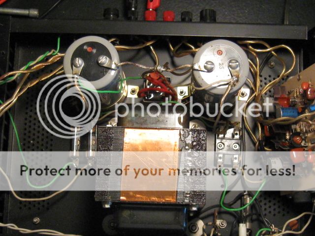
The four DC power supply fuses are in the dual fuse holders on either side of the transformer. Pop those out to isolate the circuit boards from the power supply. Use a DMM (or two) and measure the voltage across the power supply caps relative to ground. If the amp is in unknown condition, power it up using a lightbulb limiter or a variable transformer (Variac). A lightbulb limiter is simply an incandescent lightbulb placed in series with the 120VAC line to the amp. The light will glow bright for second with the turn on surge of the amp, then go dim to show proper operation. If there is a fault the light will stay lit bright, and the series resistance will keep the amp from imploding long enough for you to hit the switch.
This amps power supply was fine, and since Brokencrank had tested the amp previously I went ahead and powered up each channel one at a time to find out what was wrong. The right channel was ok, with low DC offset (DC voltage measured at the output terminals). The left channel had higher DC offset, and had an open circuit somewhere in the output fuse wiring. The output fuses in these amps are inside the feedback loop of these amps, which reduces any distortion caused by the fuse in the signal path. If the fuse network is open anywhere, output will be reduced dramatically as it is then only able to go through R35.
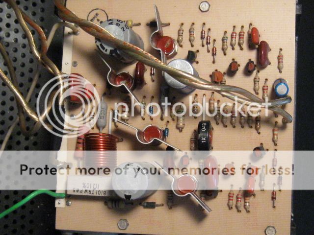
In this photo, you can see the shoddy wiring. The main power supply and output wiring is along the bottom of the circuit boards (left side of this view), and the input wiring is at the top. The input wiring should be a ~22AWG tightly twisted pair or shielded wire, not the the lightly twisted 16AWG pair you see here. Also in this photo, you can see that mostly carbon film resistors with a 5% tolerance were used in the DH200. These are fine, but should be checked to make sure their value hasn't drifted over time and heat cycles. Particularly around the input stage, drifting resistor values can cause excessive DC offset at the output and increased distortion due to imbalances in the differential pairs. Resistor sets that should be checked at a minimum:
R6, R7, R17, R19 = 2.2K ohms
R9, R10, R15, R16 = 22 ohms
R12, R14 = 560 ohms
R11, R13 = 39K ohms
R4, R5, R20, R21 = 100 ohms
These don't have to be pulled to be measured. They can all be measured when the input transistors are pulled. In this DH200 all were fine except R12 and R14 which had drifted some. Those two resistors set the current flowing through each differential pair. If there is an imbalance there DC offset and possibly distortion will be increased. I replaced them with new metal film resistors.*
All of the transistors in the input stage should be pulled and checked for beta and leakage. I use an old Heathkit IT-18 transistor checker for this. Most DMM's have an HFE function, but this will only tell you part of the story. I highly recommend anyone getting into this side of the hobby get an IT-18 or similar transistor checker. Alternatively, these testers are pretty simple so you could build something that would do the same thing, or even better, but the commercial testers are convenient. Q1, Q2, Q5, and Q6 should all be matched for beta. Q3, and Q4 should also be matched. If the transistors need to be replaced, I found picking matched sets to be very easy if you stick to large vendors like Digikey and Mouser for parts as even transistors bought in bulk packaging will be from the same batch. I don't advocate wholesale component replacement when repairing equipment, but in this case since I had to pull the transistors to check them anyway I just replaced them with new parts. The early DH200's used MPS8099/MPS8599 transistors for the differential pairs, and BC546/BC556 transistors for the current sources. For all later amps they used 2N5551/2N5401 (or the lower voltage 2N5550/2N5400) in all locations. The MPS parts are still in production, but I use the 2N devices for no reason other than they are typically cheaper as more companies make them. ON Semi is the only current manufacturer of the MPS8099/MPS8599 pair that I know of.
Note: Be careful soldering and de-soldering on the ccircuit boards. The traces will lift if too much heat is applied for too long. You should use a temperature controlled solder station for this type of work, or at the least a power controlled station like the Weller WLC100. Use a solder sucker instead of solder braid. Don't rush it.
There are four electrolytic capacitors on the circuit boards that should be replaced on the DH200. Later models used a film cap at the input. C7 and C10 are the power supply decoupling caps for the VAS and input stage. They are polarized 100uF/80Vdc. 100Vdc rated parts will be much easier to find. The third electrolytic (C5) is a non-polar 470uF 6.3V cap in feedback loop reducing the DC gain of teh amp to zero. Fourth is C1, a 10uF which blocks DC at the input. For replacements I used standard Nichcon for the 100uF's, and Nichicon Muse non-polar for the input and feedback caps. To get the right size and lead spacing I used a 16V part for C5, and 50V for C1.
The wiring was replaced with PTFE (Teflon) insulated, silver coated copper 18AWG wire from ApexJr. The input wiring was replaced with PTFE 22AWG shielded wire (also available from ApexJr).
One channel done... Rinse and repeat.
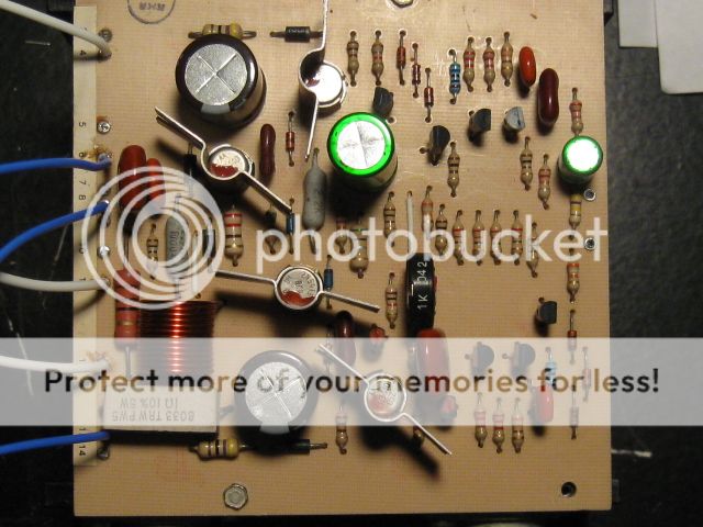
Once I got to this stage I powered up the completed, individual channel with a benchtop power supply ramping up to +/-25Vdc. As you increase the power supply voltage the output DC offset will jump up, until the voltage is high enough for the circuit to stabilize. This is normal, just watch the current draw. These amps work fine at this low voltage, and it allows you to do basic operation checks. As long as the circuit is drawing less than ~300mA from the power supply (will vary depending on the bias setting, controlled by the trimpot P1), and the DC voltage measured at the output is low (less than 100mVdc) the circuit is probably functioning OK.
Congratulations to the people (person?) that actually read this far. Part 2 will have final assembly notes and more rambling.
David Hafler (RIP) must have sold tons of these amps... There are always a wide selection of different models on ebay, but the DH200 and DH220 seem to be the most common. I have three of my own (2 P230's and a P125) that I cycle in and out of use. I've repaired and rebuilt several for other people, and yet I keep running into more of them. The most recent being Brokencrank's DH200, which I have documented below for reference, and to have a place to put my notes. I don't claim any of the info below to be gospel, just my experience. I also don't claim this to be a step by step guide to resuscitate your old Hafler. A basic understanding of electronics and amplifiers will be required. Know what you're doing before you do it, and you will make less mistakes. If you have questions, ask!*
Note: All of the component reference numbers (ie. R3, C14, Q10, etc...) I mention will be based on the schematics available in the manuals at Hafler.com. Because this will be mainly about the DH200 in particular I will only mention reference numbers pertaining to that schematic, on page 13 of this manual:*https://hafler.com/techsupport/pdf/DH-200_amp_man.pdf
History Lesson: The DH200 (later the DH220) and the DH500 were originally available as kits to be assembled by hobbyists, not unlike the Heathkit and Dynaco products. While great, this, in combination with the various modification articles that have been written, makes opening some of these amps like a box of chocolates. You never know what you're going to get mainly because the quality control of most garage workshops tends to vary. The main difference between the DH200 and the DH220 is the circuit board, and associated component changes. Most consider the DH220 an upgrade to the DH200. The DH500 had a similar design change mid-production but it did not accompany a model name change. The P230 is almost the same electrically as the DH220, difference being it has an extra pair of output MOSFET's for greater reliability into 4ohm loads. The XL280 and the SE240 are also similar to the earlier DH models, but have JFET's in the input stage, and different circuit board designs. The DH120, P125 and SE120 are also pretty similar to each other electrically. All of the Hafler models developed a good reputation as studio monitor amplifiers, and for lower power PA applications. The DH500, P500 and XL600 are better suited to being mounted in a rack as they have forced air cooling.
Techno-Babble
Design Summary: The DH200 has a dual differential input stage, a symmetrical voltage amplification stage (VAS) with darlington pairs, class A output driver stage, and two pairs of Hitachi lateral MOSFET's biased into class AB. There is nothing magical about the circuit design of these amps, and in general, except for the fact they were pretty high quality in a low to mid-fi price range. The power transformer is sized well for the output power, my guess being 400-450VA. The heatsinks are also good sized, assuming the amp isn't buried in a PA rack with other hot running gear or spaces with low ventalation. All of the DH model amps have RCA jacks and two prong power cords. The P225, P230, and P125 have 1/4" non-balanced inputs, ability to be bridged, and three prong power cords. some of the later PRO series amps have XLR balanced inputs.
This particular DH200 had some really bad wiring. The kits came with decent wire, but for whatever reason this amp was built, or rebuilt, with ~16AWG lamp cord. Most of the wired connections to the circuit boards were just tacked on to the eyelets, not actually through the circuit board and soldered to the circuit traces. Because of this only one channel worked. First step was to remove the two fuses for each channel that are in the +DCV and -DCV lines (fuses F2L, F2R, F3L, F3R) and test the power supply.*
Note: Be sure the main power supply filtering caps (C16, C17) are discharged when working inside an amp, and never have your hands in a device that is plugged in.
The proper way to discharge the caps is with a ~100ohm to 1Kohm 1W resistor. It will get hot, so hold it with needle nose pliers.
Typical rail voltages in these amps is +/-58Vdc to +/-64Vdc depending on your AC mains voltage at the wall.
The four DC power supply fuses are in the dual fuse holders on either side of the transformer. Pop those out to isolate the circuit boards from the power supply. Use a DMM (or two) and measure the voltage across the power supply caps relative to ground. If the amp is in unknown condition, power it up using a lightbulb limiter or a variable transformer (Variac). A lightbulb limiter is simply an incandescent lightbulb placed in series with the 120VAC line to the amp. The light will glow bright for second with the turn on surge of the amp, then go dim to show proper operation. If there is a fault the light will stay lit bright, and the series resistance will keep the amp from imploding long enough for you to hit the switch.
This amps power supply was fine, and since Brokencrank had tested the amp previously I went ahead and powered up each channel one at a time to find out what was wrong. The right channel was ok, with low DC offset (DC voltage measured at the output terminals). The left channel had higher DC offset, and had an open circuit somewhere in the output fuse wiring. The output fuses in these amps are inside the feedback loop of these amps, which reduces any distortion caused by the fuse in the signal path. If the fuse network is open anywhere, output will be reduced dramatically as it is then only able to go through R35.
In this photo, you can see the shoddy wiring. The main power supply and output wiring is along the bottom of the circuit boards (left side of this view), and the input wiring is at the top. The input wiring should be a ~22AWG tightly twisted pair or shielded wire, not the the lightly twisted 16AWG pair you see here. Also in this photo, you can see that mostly carbon film resistors with a 5% tolerance were used in the DH200. These are fine, but should be checked to make sure their value hasn't drifted over time and heat cycles. Particularly around the input stage, drifting resistor values can cause excessive DC offset at the output and increased distortion due to imbalances in the differential pairs. Resistor sets that should be checked at a minimum:
R6, R7, R17, R19 = 2.2K ohms
R9, R10, R15, R16 = 22 ohms
R12, R14 = 560 ohms
R11, R13 = 39K ohms
R4, R5, R20, R21 = 100 ohms
These don't have to be pulled to be measured. They can all be measured when the input transistors are pulled. In this DH200 all were fine except R12 and R14 which had drifted some. Those two resistors set the current flowing through each differential pair. If there is an imbalance there DC offset and possibly distortion will be increased. I replaced them with new metal film resistors.*
All of the transistors in the input stage should be pulled and checked for beta and leakage. I use an old Heathkit IT-18 transistor checker for this. Most DMM's have an HFE function, but this will only tell you part of the story. I highly recommend anyone getting into this side of the hobby get an IT-18 or similar transistor checker. Alternatively, these testers are pretty simple so you could build something that would do the same thing, or even better, but the commercial testers are convenient. Q1, Q2, Q5, and Q6 should all be matched for beta. Q3, and Q4 should also be matched. If the transistors need to be replaced, I found picking matched sets to be very easy if you stick to large vendors like Digikey and Mouser for parts as even transistors bought in bulk packaging will be from the same batch. I don't advocate wholesale component replacement when repairing equipment, but in this case since I had to pull the transistors to check them anyway I just replaced them with new parts. The early DH200's used MPS8099/MPS8599 transistors for the differential pairs, and BC546/BC556 transistors for the current sources. For all later amps they used 2N5551/2N5401 (or the lower voltage 2N5550/2N5400) in all locations. The MPS parts are still in production, but I use the 2N devices for no reason other than they are typically cheaper as more companies make them. ON Semi is the only current manufacturer of the MPS8099/MPS8599 pair that I know of.
Note: Be careful soldering and de-soldering on the ccircuit boards. The traces will lift if too much heat is applied for too long. You should use a temperature controlled solder station for this type of work, or at the least a power controlled station like the Weller WLC100. Use a solder sucker instead of solder braid. Don't rush it.
There are four electrolytic capacitors on the circuit boards that should be replaced on the DH200. Later models used a film cap at the input. C7 and C10 are the power supply decoupling caps for the VAS and input stage. They are polarized 100uF/80Vdc. 100Vdc rated parts will be much easier to find. The third electrolytic (C5) is a non-polar 470uF 6.3V cap in feedback loop reducing the DC gain of teh amp to zero. Fourth is C1, a 10uF which blocks DC at the input. For replacements I used standard Nichcon for the 100uF's, and Nichicon Muse non-polar for the input and feedback caps. To get the right size and lead spacing I used a 16V part for C5, and 50V for C1.
The wiring was replaced with PTFE (Teflon) insulated, silver coated copper 18AWG wire from ApexJr. The input wiring was replaced with PTFE 22AWG shielded wire (also available from ApexJr).
One channel done... Rinse and repeat.
Once I got to this stage I powered up the completed, individual channel with a benchtop power supply ramping up to +/-25Vdc. As you increase the power supply voltage the output DC offset will jump up, until the voltage is high enough for the circuit to stabilize. This is normal, just watch the current draw. These amps work fine at this low voltage, and it allows you to do basic operation checks. As long as the circuit is drawing less than ~300mA from the power supply (will vary depending on the bias setting, controlled by the trimpot P1), and the DC voltage measured at the output is low (less than 100mVdc) the circuit is probably functioning OK.
Congratulations to the people (person?) that actually read this far. Part 2 will have final assembly notes and more rambling.
Total Comments 5
Comments
-

 Hard to believe that 152 of us have gained knowledge from you and this article, but none yet said "Thank you".
I will be the first then.
Thank you for taking the time to write an informative and humorous blog about our well used and loved Hafflers. Mine is limping on one leg and sits on a shelf in the garage awaiting repairs. I now know where to start looking.
Maybe after the F5 turbo ........... It will rise again!!!
Renron
Edit,
I'd read part 2. And enjoy it too.
I like your writing style.Posted 27th December 2012 at 10:10 PM by Renron

Updated 27th December 2012 at 10:12 PM by Renron -
 Thanks for the support. I will get going on the 2nd part.Quote:Originally Posted by Renron
 Hard to believe that 152 of us have gained knowledge from you and this article, but none yet said "Thank you".
I will be the first then.
Thank you for taking the time to write an informative and humorous blog about our well used and loved Hafflers. Mine is limping on one leg and sits on a shelf in the garage awaiting repairs. I now know where to start looking.
Maybe after the F5 turbo ........... It will rise again!!!
Renron
Edit,
I'd read part 2. And enjoy it too.
I like your writing style.Posted 31st December 2012 at 12:48 PM by Stormrider
-
 Thanks for the info, im doing my research before I tackle my DH200. I have wanted one since they were new, I even ordered the manual from Hafler.
Finally I found one that is super clean and functoning offsets are a bit high 25mv/50mv.
Your article has given me great information, Id like my 200 to be good as new.
bobPosted 19th January 2014 at 02:00 AM by Rjones5296
-
This was helpful,I have a very stock board (other than recap,and repair(no mods)and it was great to see a original pc 6 to compare to.Posted 10th April 2014 at 04:13 PM by KTnC
-
Thank you as well. Anyone who spends the time to share knowledge in an organized way adds to the good karma in the world.Posted 9th January 2015 at 01:49 AM by Halauhula

