

This is just an area I can blab on about stuff without it using up bandwidth in the threads  Hopefully someone will find it interesting or useful.
Tony.
Hopefully someone will find it interesting or useful. Tony.
Construction of a P2P LM3886 gainclone part 2.
Posted 20th November 2009 at 03:44 AM by wintermute
Updated 25th November 2009 at 12:18 PM by wintermute (Added to category amplifiers)
Updated 25th November 2009 at 12:18 PM by wintermute (Added to category amplifiers)
edit: applogies to anyone viewing this at less than 1280 screen width... It formats properly with that (two images side by side) but I'm not going to go and redo all the images now!!! I already did twice....
OK Continuing on where Part 1 left off. The next step was to attach the Power Supply wiring. I will continue the numbering from the first blog entry for consistency.
18. 19.
19. 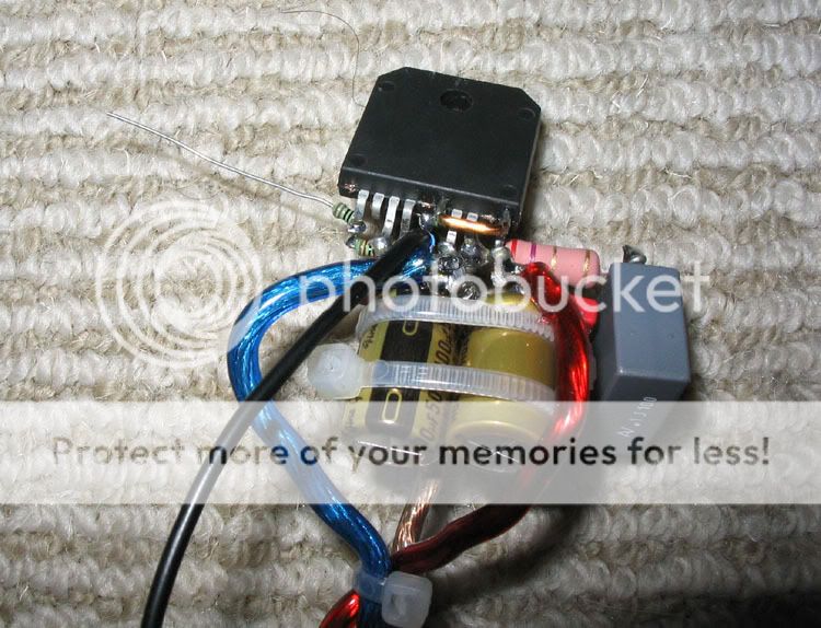
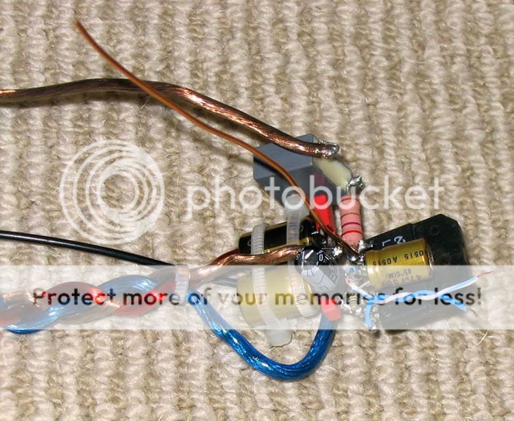
images 18 and 19 show the completed amplifier with +ve -ve and zero volts wires connected. Note also that there is a separate zero volts return from the zobel capacitor to the star ground on the PS board. The red wire is the +ve the blue wire the -ve and the green wire is the zero volts. The return for the speakers is direct from the speaker output jack to the star point on the PS board. So in all there are three returns from the chip, and a fourth for the speakers. Image 19 is supposed to show how the +ve and -ve PS wires are attached but it just looks like some big blobs of solder. Honestly nothing is shorting! I didn't go overboard with the gauge of the wiring for PS but it was nonetheless a PITA to solder to the assembly, and by far the hardest part of the entire job. If you look carefully you will see a continuity error in the photos, That is because I took most of the photos when building the second channel, but for some reason didn't take any of the PS wiring attached, which I had to use pics from the construction of the first channel for.
I will now move on to the power supply. I decided not to use one of the common power supply designs currently in vogue at the time, and do my own version. I went with the minimal cap approach (only 1000uF per rail per channel) and used BYV32E-200 diodes (which were recommended by Hugh Dean). These are a little unusual in that they have two diodes in a three terminal pack, configured as one half of a rectifier, they don't have a complementary version (that I am aware of) though (for the other half of the rectifier) for this reason it is possible to make a full wave bridge from just three of the packages (instead of the usual four).
19. 20.
20. 
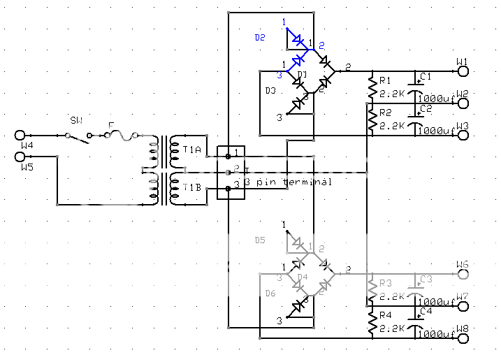
The circuit diagram for the power supply is shown in image 19. I highlighted one of the diodes so you can see the configuration. The "unused" diode is wired so that it is effectively shorted. I tossed up whether I should wire them in parallel but decided it best to just effectively remove it from the circuit.. I didn't like the idea of it floating. Figure 20 shows the plan I did for the verro board. Bit of overkill for such a simple circuit but I quite like the express pcb software and it didn't take long to mock it up. Although not shown on the board mock up, there is a bolt in the centre of the caps which forms the star ground point.
21. 22.
22. 
The PS board is basically very simple as can be seen in pictures 21 and 22. I put the bleeder resistors on the reverse side of the board to allow for room on the other side to add more caps should I think it necessary. In then end I didn't think it needed any additional capacitance. The wires which can be seen in 22 are the AC from the transformer. and the bolt in the center of the board is the star earth point. As you can no doubt see, the board met with a slight accident which some super glue fixed. You will probably also notice a couple of seemingly random cuts in the tracks at the top left of the board. This was me practicing cutting the tracks, in the end I used a dentists drill on my dremel which worked very nicely.
23. 24.
24. 
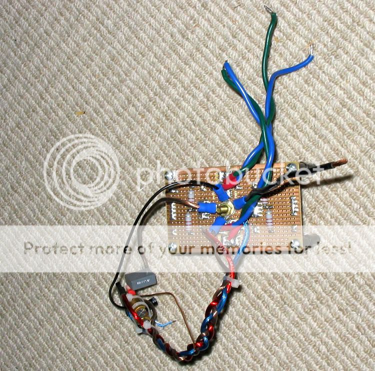
Picture 23 shows the completed module connected to the power supply. The wiring on the star point is in the following order. Bottom lug goes to the terminal block which has the two transformer windings connected. next is (I think as it isn't connected in this photo) the speaker return. The main zero volt line to the decoupling caps is next followed by the return from the zobel cap. Finally the return from pin 7 and the negative feedback is last (this is also the point where the input ground terminates). 24. Shows the earth loop breaker that I made (based on the circuit on Rod Elliot's site). This was a necessity as the original purpose for this amp was as a speaker testing amp, and because the PC it is connected to is also grounded, earth loops were an issue.
I'll now post some pictures of the construction of the chassis for the amplifier. I basically used stuff I had lying around. The heat sink was off a 48V regulated supply from a Fujitsu M380A Mainframe. The sides of the chassis were made from bits of aluminium which had previously formed the carrier cases for the CPU boards for the same mainframe, and the base was some left over MDF I had. So apart from Time the chassis really cost me nothing.
25.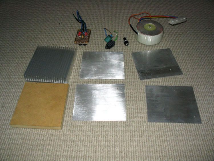 26.
26. 
25. shows the pieces cut and the power supply components Since the plan was to use the heat sink as the top of the box everything was made to fit around that. 26. shows the less than perfect results that come from being to hasty! My nibbling tool bit the dust when doing the hole for the IEC power connector and I decided to use the piece of steel from the power supply I had taken it from as a template and cut it out with a tungsten carbide tip on the dremel... BAD idea!! The later holes I chain drilled and filed with much better results! Even the holes for the rca and speaker jacks are very rough. mainly due to not having a drill press and inadequate clamping... Note that the extraneous holes were holes that were already present in the aluminum sheet before I started.
27. 28.
28. 
27. shows that with a bit of patience (the oval hole was the last one, was still a bit shaky on the rectangular one) good results can be had with nothing more than a hand drill and some files. picture 28 just a quick put together to make sure everything was going to fit! It is definitely tight...
29. 30.
30. 
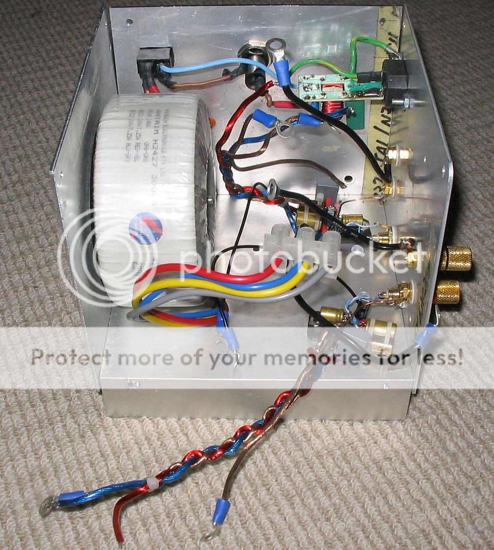
Picture 29. shows things coming together. Both LM3886's are mounted to the heat sink and connected to the rear panel jacks. This was a bit tricky as I kept the leads as short as practical as one of the design philosophies of this amp was to keep the signal paths as short as possible! 30. shows the mess that is the power supply wiring! I was really concerned about my star earthing up until the point when I connected the amp to the speakers, after which I decided it was a complete success! The amp is dead quiet with only the slightest his audible if you put your ear right against the tweeter.
31. 32.
32. 
Image 31 shows just how tight the whole package is. All the more surprising that it is dead quiet. The transformer is an Antrim one made under license by Harburch at Hornsby. it is a 300VA 240V primary 2 X 20V secondary and after rectification provides +- 28V. Image 32 is a back view of the completed amplifier.
33. 34.
34. 
33 and 34 are just different angles of the completed amp
I guess it wouldn't be complete unless I provided a BOM, so here goes:
Amplifier:
2 X LM3886TF chips $4.66 each $9.32 futurlec
2 X red RCA $1.60 each $3.20 futurlec
2 X black RCA $1.60 each $3.20 futurlec
2 X red binding post 0.60 each $1.20 futurlec
2 X black binding post 0.60 each $1.20 futurlec
4X wima MKS-02 0.1uf polyester caps 0.85 $3.40 RS components (main bypass caps).
4 X nichicon FG 100uf 50V $1.41 $5.64 RS components (main PS decoupling caps)
2 X Rubycon YXA 100uf 35V 0.33 0.66 RS Components (mute caps)
2 X Nichicon FG 47uF 50V $1.02 $2.04 RS Components (feedback cap)
2 X Arcotronics 0.1uF 100V film-foil polypropylene $1.36 $2.72 RS components (zobel caps).
2 X Kayama 1K 0.25W Metal film resistors 0.07 0.14 RS Components
4 X Kayama 22k 0.25W Metal film resistors 0.07 0.14 RS Components
2 X Kayama 680R 0.25W Metal Film resistors 0.07 0.14 RS components
2 X Kayama 10K 0.25W Metal Film resistors 0.07 0.14 RS Components.
2 X 2.7R 2W Resistors Unknown est 0.30 0.60
Total cost of amp components $33.74
Note that I would not recommend the futurlec binding posts and rca jacks. The gold has rubbed off (after minimal insertions and removals) on the rca sockets. and the speaker binding posts have dulled. I can't find the receipt for the zobel resistors but suspect that they were just plain old metal oxide ones probably from Wagner Electronic Services possibly non-inductive.
Power Supply:
1 X Antrim H2427 300VA 240:2 X 20V Toroid $61.88 Harbuch Electronics
6 X Phiilips BYV32E-200 Diodes $1.97 $11.82 RS Components
4 X Panasonic FC 1000uf 50V 3.21 $13.64
4 X 2.2K 2W resistors Unknown est .30 $1.20
1 X Fuse Holder $1.45 Altronics
1 X 3AG Slow Blow 3A fuse $2.00 Altronics
1 X Terminal strip Unknown est $1.50
1 X IEC Power Plug Free (from dead pc power supply)
1 X Power switch Free (from dead pc power supply)
Misc wire OFC est $2.00 Wagner Electronics Services
Total for power supply $95.49
Chassis free!
Total cost of amp $129.23 AU in Oct 2005.
As can be seen the power supply was by far the most expensive part of the amplifier, and it is only a simple one using small caps! The cost would also have been significantly higher if I needed to purchase a chassis and heat sink.
This was probably the fastest DIY project I have ever done, I ordered the LM3886's on 23rd Sep (slow delivery) built and tested the power supply on the 17th Oct cut the parts for the chassis on 19th Oct, started work on the p2p on 21st Oct, 1st p2p module completed 25th Oct, and everything complete 2nd Nov. So only about 2 weeks from the time the chips arrived to completion... I wish all my projects were like that!!!
Tony.
OK Continuing on where Part 1 left off. The next step was to attach the Power Supply wiring. I will continue the numbering from the first blog entry for consistency.
18.
19. images 18 and 19 show the completed amplifier with +ve -ve and zero volts wires connected. Note also that there is a separate zero volts return from the zobel capacitor to the star ground on the PS board. The red wire is the +ve the blue wire the -ve and the green wire is the zero volts. The return for the speakers is direct from the speaker output jack to the star point on the PS board. So in all there are three returns from the chip, and a fourth for the speakers. Image 19 is supposed to show how the +ve and -ve PS wires are attached but it just looks like some big blobs of solder. Honestly nothing is shorting! I didn't go overboard with the gauge of the wiring for PS but it was nonetheless a PITA to solder to the assembly, and by far the hardest part of the entire job. If you look carefully you will see a continuity error in the photos, That is because I took most of the photos when building the second channel, but for some reason didn't take any of the PS wiring attached, which I had to use pics from the construction of the first channel for.
I will now move on to the power supply. I decided not to use one of the common power supply designs currently in vogue at the time, and do my own version. I went with the minimal cap approach (only 1000uF per rail per channel) and used BYV32E-200 diodes (which were recommended by Hugh Dean). These are a little unusual in that they have two diodes in a three terminal pack, configured as one half of a rectifier, they don't have a complementary version (that I am aware of) though (for the other half of the rectifier) for this reason it is possible to make a full wave bridge from just three of the packages (instead of the usual four).
19.
20. The circuit diagram for the power supply is shown in image 19. I highlighted one of the diodes so you can see the configuration. The "unused" diode is wired so that it is effectively shorted. I tossed up whether I should wire them in parallel but decided it best to just effectively remove it from the circuit.. I didn't like the idea of it floating. Figure 20 shows the plan I did for the verro board. Bit of overkill for such a simple circuit but I quite like the express pcb software and it didn't take long to mock it up. Although not shown on the board mock up, there is a bolt in the centre of the caps which forms the star ground point.
21.
22. The PS board is basically very simple as can be seen in pictures 21 and 22. I put the bleeder resistors on the reverse side of the board to allow for room on the other side to add more caps should I think it necessary. In then end I didn't think it needed any additional capacitance. The wires which can be seen in 22 are the AC from the transformer. and the bolt in the center of the board is the star earth point. As you can no doubt see, the board met with a slight accident which some super glue fixed. You will probably also notice a couple of seemingly random cuts in the tracks at the top left of the board. This was me practicing cutting the tracks, in the end I used a dentists drill on my dremel which worked very nicely.
23.
24. Picture 23 shows the completed module connected to the power supply. The wiring on the star point is in the following order. Bottom lug goes to the terminal block which has the two transformer windings connected. next is (I think as it isn't connected in this photo) the speaker return. The main zero volt line to the decoupling caps is next followed by the return from the zobel cap. Finally the return from pin 7 and the negative feedback is last (this is also the point where the input ground terminates). 24. Shows the earth loop breaker that I made (based on the circuit on Rod Elliot's site). This was a necessity as the original purpose for this amp was as a speaker testing amp, and because the PC it is connected to is also grounded, earth loops were an issue.
I'll now post some pictures of the construction of the chassis for the amplifier. I basically used stuff I had lying around. The heat sink was off a 48V regulated supply from a Fujitsu M380A Mainframe. The sides of the chassis were made from bits of aluminium which had previously formed the carrier cases for the CPU boards for the same mainframe, and the base was some left over MDF I had. So apart from Time the chassis really cost me nothing.
25.
26. 25. shows the pieces cut and the power supply components Since the plan was to use the heat sink as the top of the box everything was made to fit around that. 26. shows the less than perfect results that come from being to hasty! My nibbling tool bit the dust when doing the hole for the IEC power connector and I decided to use the piece of steel from the power supply I had taken it from as a template and cut it out with a tungsten carbide tip on the dremel... BAD idea!!
The later holes I chain drilled and filed with much better results! Even the holes for the rca and speaker jacks are very rough. mainly due to not having a drill press and inadequate clamping... Note that the extraneous holes were holes that were already present in the aluminum sheet before I started. 27.
28. 27. shows that with a bit of patience (the oval hole was the last one, was still a bit shaky on the rectangular one) good results can be had with nothing more than a hand drill and some files. picture 28 just a quick put together to make sure everything was going to fit! It is definitely tight...
29.
30. Picture 29. shows things coming together. Both LM3886's are mounted to the heat sink and connected to the rear panel jacks. This was a bit tricky as I kept the leads as short as practical as one of the design philosophies of this amp was to keep the signal paths as short as possible! 30. shows the mess that is the power supply wiring! I was really concerned about my star earthing up until the point when I connected the amp to the speakers, after which I decided it was a complete success! The amp is dead quiet with only the slightest his audible if you put your ear right against the tweeter.
31.
32. Image 31 shows just how tight the whole package is. All the more surprising that it is dead quiet. The transformer is an Antrim one made under license by Harburch at Hornsby. it is a 300VA 240V primary 2 X 20V secondary and after rectification provides +- 28V. Image 32 is a back view of the completed amplifier.
33.
34. 33 and 34 are just different angles of the completed amp
I guess it wouldn't be complete unless I provided a BOM, so here goes:
Amplifier:
2 X LM3886TF chips $4.66 each $9.32 futurlec
2 X red RCA $1.60 each $3.20 futurlec
2 X black RCA $1.60 each $3.20 futurlec
2 X red binding post 0.60 each $1.20 futurlec
2 X black binding post 0.60 each $1.20 futurlec
4X wima MKS-02 0.1uf polyester caps 0.85 $3.40 RS components (main bypass caps).
4 X nichicon FG 100uf 50V $1.41 $5.64 RS components (main PS decoupling caps)
2 X Rubycon YXA 100uf 35V 0.33 0.66 RS Components (mute caps)
2 X Nichicon FG 47uF 50V $1.02 $2.04 RS Components (feedback cap)
2 X Arcotronics 0.1uF 100V film-foil polypropylene $1.36 $2.72 RS components (zobel caps).
2 X Kayama 1K 0.25W Metal film resistors 0.07 0.14 RS Components
4 X Kayama 22k 0.25W Metal film resistors 0.07 0.14 RS Components
2 X Kayama 680R 0.25W Metal Film resistors 0.07 0.14 RS components
2 X Kayama 10K 0.25W Metal Film resistors 0.07 0.14 RS Components.
2 X 2.7R 2W Resistors Unknown est 0.30 0.60
Total cost of amp components $33.74
Note that I would not recommend the futurlec binding posts and rca jacks. The gold has rubbed off (after minimal insertions and removals) on the rca sockets. and the speaker binding posts have dulled. I can't find the receipt for the zobel resistors but suspect that they were just plain old metal oxide ones probably from Wagner Electronic Services possibly non-inductive.
Power Supply:
1 X Antrim H2427 300VA 240:2 X 20V Toroid $61.88 Harbuch Electronics
6 X Phiilips BYV32E-200 Diodes $1.97 $11.82 RS Components
4 X Panasonic FC 1000uf 50V 3.21 $13.64
4 X 2.2K 2W resistors Unknown est .30 $1.20
1 X Fuse Holder $1.45 Altronics
1 X 3AG Slow Blow 3A fuse $2.00 Altronics
1 X Terminal strip Unknown est $1.50
1 X IEC Power Plug Free (from dead pc power supply)
1 X Power switch Free (from dead pc power supply)
Misc wire OFC est $2.00 Wagner Electronics Services
Total for power supply $95.49
Chassis free!
Total cost of amp $129.23 AU in Oct 2005.
As can be seen the power supply was by far the most expensive part of the amplifier, and it is only a simple one using small caps! The cost would also have been significantly higher if I needed to purchase a chassis and heat sink.
This was probably the fastest DIY project I have ever done, I ordered the LM3886's on 23rd Sep (slow delivery) built and tested the power supply on the 17th Oct cut the parts for the chassis on 19th Oct, started work on the p2p on 21st Oct, 1st p2p module completed 25th Oct, and everything complete 2nd Nov. So only about 2 weeks from the time the chips arrived to completion... I wish all my projects were like that!!!
Tony.
Total Comments 6
Comments
-
 Hi Tony,
Great inspiration!! But like a lot of other people I am sooo curious how it sounds. Could you write a little about that at the end?Posted 2nd December 2011 at 10:58 PM by jslot

-
 Hi Jslot, I made some brief comments here --> https://www.diyaudio.com/forums/chip-...ml#post1918585 Since then I have actually finished the MTM's and all silibance is gone. also the post before it. The amp has actually been in daily use for probably over a year now (since the series 200 preamp died and I was going to make my new one rather than fix it
")
One of the problems I have with answering how does it sound, is that I don't have a lot to compare it to. I have my Playmaster series 200 and that's it. I haven't actually done a comparison since I finished the MTM's which I probably should.
The real problem however is the lack of a decent source. I'm using my HTPC at the moment due to lack of a preamp, and I'm sure that it is less than optimal. I have to get off my backside and do my synergy active crossover/ preamp. Once I've done that, I think that I'll have enough resolution in the rest of the system to be able to see if I can subjectively hear any differences between the amps. I also have a baby aksa to make which I think once done (don't hold your breath) should be a good comparison
I've also upped the capacitance in the powersupply fairly recently, I added 4700uF per channel per rail. This did reduce the already very low hum on the output to almost inaudible levels.
Bass from my modest MTM's is fantastic. Very tight and controlled and much deeper than I would ever have expected (more than I'd have expected from the speakers, rather than from the amp). All in all it's very capable. I suspect that the main difference would be heard at high levels. I think my mosfet amp will outperform it in that respect purely due to its much more friendly clipping, which will likely occur on transients.
TonyPosted 4th December 2011 at 12:29 AM by wintermute
-
why PCB for the PSU, especially after such a good job of the P2P amplifier?Posted 31st May 2014 at 07:11 PM by AndrewT
-
Good question Andrew. I never actually thought about doing a p2p power supply.
I guess the philosophy with this particular project was to keep all the signal paths as short as possible, hence the extremely compact p2p. After reading tomchr's excellent thread https://www.diyaudio.com/forums/chip-...oint-data.html there are some things I could have done better. If I were to do it again I'd implement his grounding scheme (mine is close with a couple of minor differences), and I'd also drop the gain down a bit probably to 20X.
I guess with the PS I just saw it as a utility. The most important aspect (especially considering the design) was getting equal lengths for the earth connections. The easiest way I could see to do this was with the PCB
The power supply is not a complete success, but it is pretty good. There is some level of ps noise at the output of the amp (can't remember exact mv reading on the scope) but it is pretty small.
Tony.Posted 1st June 2014 at 10:56 AM by wintermute
-
Interesting project, Tony - I note many similarities to my version of a LM38xx gainclone, especially in regard to the extremely tight, point to point connections. I did go to a lot of trouble with my PS, it would have very substantially greater energy reserves, and the benefit of doing that could be clearly heard - so anything you do there I believe would be well worthwhile.
Cheers,
FrankPosted 2nd June 2014 at 02:37 AM by fas42
-
Thanks Frank. The original PS was minimal ALA Peter's low cap gainclone. I did find that the addition of 4700uF per rail reduced the noise on the output quite a lot, so definitely possible that beefing it up some more would get rid of the remaining small amount of PS noise that is getting through to the speakers.
Tony.Posted 3rd June 2014 at 09:13 PM by wintermute

