Welcome to the wonderful world of chassis making. Personally I have good experiences with punches. I use a 28.3mm punch for octal sockets, works well for me. Maybe you have slightly different sockets. Why snip a hole first? I drill the 10mm pilot hole for the punch, and then I punch, works like a charm in 3mm aluminium. What material do you use? Stainless would be A LOT more muscle work than aluminium. Always use grease or cutting oil with the punches... Also lubricate the "shoulder" of the punch where the bolt turns against the barrel... Finally try to find the correct spanner.
HTH!
Kenneth
HTH!
Kenneth
Member
Joined 2009
Paid Member
The centre bolt of the punches I have on loan are very large themselves, requiring a pretty big hole in the first place. Yep, lots of grease. It is steel and it take a fair bit of torque to cut through it. The finished holes are nice though, much better than what I would have produced with a file !
Life is always easier with the right tools, perhaps this is an opportunity to upgrade my old hand drill and to consider a 1/2" chuck. The trouble has been that no one project really justified the expense of new tools, but I guess you reach a point where you have to think ahead to future projects
I'll keep plugging ahead - next step is to get enough of the power supply built to find out what kind of B+ I can achieve with the parts I have.
Of course it's your money, and they're not exactly cheap, but maybe you could consider buying your own punches (with smaller center bolts!) -- just two punches will equip you for octal & noval sockets, which is about >95% of all tubes out there. And they last a lifetime.
You're right, not many power cutting tools come close to punches w.r.t. the quality of the finish of the hole! Plus, it's much more satisfying to make big holes in metal without power tools
Might I also suggest to give 2 or 3mm aluminium a try just to get an idea -- you'll be surprised how much easier it goes compared to steel!
Kenneth
Member
Joined 2009
Paid Member
These punches are darn expensive. I only want to cut 3 holes and I don't know if I'll ever want to build another tube amp yet - I've never heard a tube amp still so this is the first chance.
Well, I invested in a new drill because I know that'll get plenty of use either way. But the punches I have borrowed simply aren't the right size for my tube sockets. I had to file the holes out to achieve the right size. I treated myself to a round file for the job. After some time this evening I've now got the 3 socket holes done. They ain't pretty but they are going to do the job. Next project I'm buying tube sockets to suit the punches I can borrow. Right now, I feel like telling my power transistors that all is forgiven....
DigiKey should be on my doorstep shortly with some extra bits - power resistors, fuses, power switch and some caps. I love it when the parcels arrive
Member
Joined 2009
Paid Member
Member
Joined 2009
Paid Member
I've now put a lot more holes in the chasis. My bits turned up from Digikey too. I've also made a nice Oak wood frame for the chasis.
Unfortunately, the cut side of the chasis (it was cut down from a larger one) doesn't have the support of a metal side and it bows slightly under the weight of the trafo's.
It looks like all this will have to be scrapped again.
Unfortunately, the cut side of the chasis (it was cut down from a larger one) doesn't have the support of a metal side and it bows slightly under the weight of the trafo's.
It looks like all this will have to be scrapped again.
Unfortunately, the cut side of the chasis (it was cut down from a larger one) doesn't have the support of a metal side and it bows slightly under the weight of the trafo's.
It looks like all this will have to be scrapped again.
This thread is making me nervous, so much trouble to build a simple amp. Your "big" problem has an easy solution, hint - chassis can use wood as a crutch. By Jove!, just make it sound. What's the use of spending so much time building the chassis if you don't know it's a keeper.
Member
Joined 2009
Paid Member
Yes indeed. Too much futzing around, it won't do it all, I'm in danger of letting the side down !
I'll plug on and finish this chasis to a point that I can wire the thing up. The next time you hear from me I'll have a photo of the finished thing.
Will it be a keeper ? - well given the shortcomings I'm planning on this first build as being the 'practice run' based on the 6AS7. It'll end up life somewhere other than in my main system, perhaps on my desktop with nearfield monitors where I can feel the heat !
Stalker - great result last Sunday, my family was rooting for you
Wavebourn - I can't be building my amp out of cheese grater now !
Last edited:
Member
Joined 2009
Paid Member
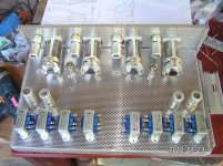
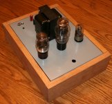
I worked late, but a complete first assembly isn't there yet. Here are a couple of photos of the first test-for-fit assembly. I guess I will have to live with the limitations of my workmanship for this one - and hope to goodness I fit the wiring in there, it's a bit tight.
Attachments
Not really trying to rain on your parade, but probably am.. Sorry..
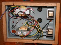
Mounting the OPTs directly under the power transformer is probably not such a good idea. Even though they are mounted in different planes there is going to be some stray field from that power transformer that could couple into those OPTs, inducing hum in the output. (This is somewhat less of an issue with amps using global feedback.)
You can test this by powering the power transformer (make sure all leads are insulated so they cannot short).. Place a 600 ohm resistor across the primary of each OPT and measure the voltage across the secondaries of the OPTs. Anything more than a mVrms or so is a cause for concern.
It is also extremely tight, where are you going to put the supply capacitors and cathode power resistors assuming this is cathode biased? I hope you can get it to all fit.. Better to use a box that is a little on the large side than to try and cram everything into a very small box.
One potential option would be to build the PSU in a separate, but identical box.
The wood wrap is a very nice touch though..
Last edited:
Member
Joined 2009
Paid Member
I think there will be a lot of things to discover over the next couple of weeks. Not only have I no experience to fall back on with regards transformer isolation but I can see there being a big thermal issue with the cathode resistor on the underside. I'm not even sure how much B+ I'm going to get either or whether there's enough room to keep the heater wires away from trouble.
I was about to order a new 17 x 12 box to replace the one I cut in half and use it as a test bed chasis but decided to 'practice' cutting holes in this one first before rushing to make a mess out of a new one.
Now I figure I may as well do some experimentation with it (I have a pair of 6C4C tubes on their way and this might be a preferred option for a 'final' version). If the cathode resistors generate too much heat I'll have to figure something out, maybe cut some ventilation holes, move them the topside or design a compact fixed bias source...
p.s. it will be interesting to see how much flux leakage we get from the power trafo through the chasis. It's still possible to turn those OTs and screw them into the sidewalls of the chasis.
Last edited:
Not too late to move the power transformer to another chassis.. That would buy you a lot more space to build in, and solve the magnetic issue..
Sounds like you are having fun as well as learning, and you can always rebuild it later..
One thing I can recommend from my own experience is to map the placement of major components on gridded paper, usually to scale. I even gone so far as to make cut outs of major parts and play on a to scale drawing of the chassis - you would be surprised how well this can work.. Take a look on my site at the 300B SE amp for some ideas on chassis layout approach..
That would buy you a lot more space to build in, and solve the magnetic issue.. Sounds like you are having fun as well as learning, and you can always rebuild it later..
One thing I can recommend from my own experience is to map the placement of major components on gridded paper, usually to scale. I even gone so far as to make cut outs of major parts and play on a to scale drawing of the chassis - you would be surprised how well this can work.. Take a look on my site at the 300B SE amp for some ideas on chassis layout approach..
Member
Joined 2009
Paid Member
The stupid thing is the friend of mine who gave me the stuff in the first place also gave me a pad of large squared paper for me to do just this. But of course, I knew better, decided I didn't want to build it on a huge chasis or use some kind of planing technique from the 'old days' so in my infinite new found wisdom (coming from SS) I promptly f*&&** the whole thing up by cutting the chasis in half.
With several hours invested in what I have, my penance is to struggle on and learn what I can with the current set up. If it works, that'll be a bonus. If it doesn't work then it depends on why.
If it's a lack of OT isolation I'll simply rotate them to the sides of the chasis which puts them orthogonal to the psu trafo
If it's too tight to build the thing in this small chasis I'll consider cheating by elevating the box with tall feet to create some space, maybe move the psu chokes up on top.
If it gets too hot inside the chasis, which I suspect it will, I'll probably move the cathode bias resistors to the topside of the chasis where they can get much better airflow, I can also add some ventilation holes.
What else can go wrong that can't be fixed amongst us ?
I received my 6C4C tubes today - for my 2nd project perhaps and next time I'm using the big chasis and the squared paper darn it !
I'm hoping the current project will be workble without a new chasis or a separate psu chasis and if so (can you feel the optimism/desperation?), it now looks compact enough to be useful on my computer table using iTunes as a source - in the Winter only...
Chassis is big enough. Check this amp out for inspiration:
6moons audio reviews: Decware Zen Taboo
You have big cathode resistors dissipating a lot of heat, put those away from caps but no need for ventilation holes, just leave some space for free air under the chassis. Your imagination just needs an extra effort with a small chassis, that's all. Not to say that Kevin's wrong, he's right but you did say something about WAF, didn't you?
Last edited:
Member
Joined 2009
Paid Member
OK, so a couple of things tried out today.
1/ Wired up the primary of the power trafo. I connected the OT secondary to a speaker (89dB fostex 127) to test for magnetic isolation (as suggested above).
With unloaded OT primary - hard to hear any hum, had to press my ear up against the cone and then it was a case of 'I know something is there but hard to make it out'
With OT primary loaded with 330R pretty much the same result. Not the most sensitive speaker to test it with and I didn't put a scope on it but it was good enough that I decided to proceed further without making changes to the orientation of the OTs.
2/ Wired up the rectifier socket, twisted 5V heater wires. Wired up the power trafo secondary to the rectifier socket and output to the two power chokes. Installed 100uF 315V cap on the output of each choke. Install rubber mat under feet.
Got to see my first self-wired up tube take on a nice glow !
With no load, I see B+ of 420V
With 1k2 load, I see B+ of 205V.
With 2k2 load, I see B+ of 235V. This corresponds to 107mA, which is a bit higher than I plan to run each channel at. Looks like B+ is bang on target. The no-load voltage is too high for my capacitors, may have to size a bleeder resistor to keep it in check ?
Anyhow, so far so good
- Status
- This old topic is closed. If you want to reopen this topic, contact a moderator using the "Report Post" button.
- Home
- Amplifiers
- Tubes / Valves
- my CELLINI triode amp