Well, just looking at the curves tells me the 2A3 is more linear over a larger voltage range. It has a mu close to perfection, and reasonable rp. But agreed, they are overpriced b/c people say so...
The 6AS7 is most happy running much higher than 75mA, and I really do believe it will perform best with a much lower OPT ratio so it can swing more amps and less volts. One idea is to simply parallel two OPT primaries, and series connect the secondaries, run it at >120mA and swing around +-100volts. When using both triode sections in one bottle we are limited to 12.5watts per, but if only running a single triode section we can run much more. I have for a long time, (by mistake), and no problems at all.
The 6AS7 is most happy running much higher than 75mA, and I really do believe it will perform best with a much lower OPT ratio so it can swing more amps and less volts. One idea is to simply parallel two OPT primaries, and series connect the secondaries, run it at >120mA and swing around +-100volts. When using both triode sections in one bottle we are limited to 12.5watts per, but if only running a single triode section we can run much more. I have for a long time, (by mistake), and no problems at all.
Member
Joined 2009
Paid Member
The OT's arrived today. Even these 'budget' 125ESE's are pretty heavy. Not as heavy as the power trafo mind.
The additional psu chokes allow me to run the tubes a little hotter so 80mA might be OK. neat idea to consdier doubling up on 125ESE's, but it adds quite a bit of iron to my 'simple' project.
Just adding an extra socket to allow some experimentation with 6A3's sounds simple, but I need to think a bit more about the heater supply - my power trafo has only one 6.3V and one 5V winding and with DHT it means the heater supply to my 6Sn7 will be bobbing up and down with a bit of the output signal on it - could be a cause for trouble ?? I could add a Hammond 167 later on I suppose.
Hi,Whilst tube models for spice seem to be available on the web I'm not so sure about the trafo's - I suspect the idealized models in spice are inadequate, especially for the OT ?
Anyhow, this time around I think I'm going to stick with the old fashioned pen & paper approach.
although they might not but it's fast and easy.
see what I've got View attachment 2A3_3w1.pdf
View attachment 2A3_3w1p.pdf
Just for fun.
Cheers!
SS
View attachment 6as7se2.pdf
View attachment 6as7se2p.pdf
Not so bad compare to 2a3.
Go for it.
Have fun!
SS
View attachment 6as7se2p.pdf
Not so bad compare to 2a3.
Go for it.
Have fun!
SS
Member
Joined 2009
Paid Member
I see you chose not to include the cathode resistor bypass capacitor. I was tempted to do this with the 6AS7 because it has such lo mu anyhow but for the 2A3 that is throwing away too much gain maybe ?
Can you post the FFT plots from your simulation results, that would be interesting to see ?
Just adding an extra socket to allow some experimentation with 6A3's sounds simple, but I need to think a bit more about the heater supply - my power trafo has only one 6.3V and one 5V winding and with DHT it means the heater supply to my 6Sn7 will be bobbing up and down with a bit of the output signal on it - could be a cause for trouble ?? I could add a Hammond 167 later on I suppose.
The indirectly heated cathode on the 6SN7 will not be bothered at all. Besides, the heater will be bias to a voltage above the cathode, so electrons cannot possibly get to the cathode.
Member
Joined 2009
Paid Member
That's good to know !
I haven't given up on the idea of using a triode wired pentode as suggested by Dave, whether it be an EL84, 6V6 I don't know but I'll do some reading whilst I begin construction.
I am leaning towards the idea of adding a potentiometer in a UL configuration so that I can experiment between triode, pentode and in between. These extra grids offer huge scope for playing as far as I can see, with the added benefit over the 6A3 experiment of not having direct heating so the filament hum situation is less of a worry.
View attachment 2A3_3wfft.pdf
View attachment 6as7se2fft.pdf these show only the Vout at 1V and 2V input.
Cheers
SS
View attachment 6as7se2fft.pdf these show only the Vout at 1V and 2V input.
Cheers
SS
Interesting SS.
The H2 looks about like what I get in the real world, but the H3 does not. In your sim it is much higher than what I measure. Since the 6A3 sim shows about equal H2 but lower H3 than the 6AS7, perhaps that means in the real world it will be even lower") I'm looking forward to what Bigun find out about that.
I'm looking forward to what Bigun find out about that.
The H2 looks about like what I get in the real world, but the H3 does not. In your sim it is much higher than what I measure. Since the 6A3 sim shows about equal H2 but lower H3 than the 6AS7, perhaps that means in the real world it will be even lower
I'm looking forward to what Bigun find out about that.Member
Joined 2009
Paid Member
Singh Santa,
Ok, you've drawn me back to the simulator - mainly because I think there's too much reliance on the quality of the tube models to make this very useful.
I found on the web one of the good models, triodep.inc but I also found reports of an error in the 2A3 model. I've corrected the model and I'm attaching the updated model file. You need to change the file extension from 'txt' to 'inc' in order to use it of course.
I'm also attaching my spice model file. You need to change the file extension from 'txt' to 'asc' of course.
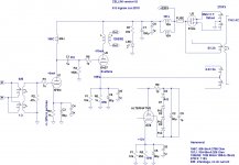
The results I get, at 1W into 8R shows very little difference in harmonic spectra between the 2A3 and 6AS7. The 2A3 has lower H2 distortion. I've set up my model to run 8mA through the 6SN7's, 60+ mA through the 2A3 and 75mA through the 6AS7. I've also included Hammond's data for the OT, it has a 9.58H primary with 90 dc resistance. I've used the 2k5 tap to determine the turns ration and hence inductance of the secondary. I'm also using an 8R load rather than 4R. Lastly, in the case of the 2A3 I've bypassed the input transformer to allow for the higher mu of the 2A3 so that the output swing from both cases is more or less the same.
p.s. the frequency response doesn't look right, seems to roll off the hf too early.
edit: I'm also beginning to suspect that the published curves for some of these tubes can't be relied on either. Some 2A3 curves look a little too good and the 6AS7 has a lot of manufacturing variability.
Ok, you've drawn me back to the simulator - mainly because I think there's too much reliance on the quality of the tube models to make this very useful.
I found on the web one of the good models, triodep.inc but I also found reports of an error in the 2A3 model. I've corrected the model and I'm attaching the updated model file. You need to change the file extension from 'txt' to 'inc' in order to use it of course.
I'm also attaching my spice model file. You need to change the file extension from 'txt' to 'asc' of course.
The results I get, at 1W into 8R shows very little difference in harmonic spectra between the 2A3 and 6AS7. The 2A3 has lower H2 distortion. I've set up my model to run 8mA through the 6SN7's, 60+ mA through the 2A3 and 75mA through the 6AS7. I've also included Hammond's data for the OT, it has a 9.58H primary with 90 dc resistance. I've used the 2k5 tap to determine the turns ration and hence inductance of the secondary. I'm also using an 8R load rather than 4R. Lastly, in the case of the 2A3 I've bypassed the input transformer to allow for the higher mu of the 2A3 so that the output swing from both cases is more or less the same.
p.s. the frequency response doesn't look right, seems to roll off the hf too early.
edit: I'm also beginning to suspect that the published curves for some of these tubes can't be relied on either. Some 2A3 curves look a little too good and the 6AS7 has a lot of manufacturing variability.
Attachments
Last edited:
Member
Joined 2009
Paid Member
Wow, I've just seen the curves for the trioded CV6 - they are very nice !
This will be interesting, 6AS7 vs 6V6.
The trioded 6V6 is very well suited for Cellini as an alternative because the grid potential is so low at -12V it allows me to drop the value of the cathode bias resistor and increase the plate voltage considerably. Since the 6V6 wants more plate voltage than the 6AS7 this seems to be a great convenience.
The 6V6 has lower heater current to boot.
I'll try this whole thing without the input transformers first. The higher mu of the 6L6 certainly doesn't need it unless I want to wire up for balanced input.
Funny thing is, I was looking at Tetrodes many moons ago when I had even less of a clue as to what they are (http://www.diyaudio.com/forums/tube...omplementary-feedback-pair-2.html#post1912948)
p.s. can you spot the missing diode in my schematic ?
Attachments
Last edited:
Member
Joined 2009
Paid Member
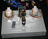
the pieces are starting to come together - although SWMBO says the chasis is too big (17" x 12") so that might have to change
IME, it's hard to change a SWBMO. But don't let me stop you trying
Member
Joined 2009
Paid Member
IME, it's hard to change a SWBMO. But don't let me stop you trying
It'd be safer playing with 1kV tubes
Hi,
I built my using lesser irons.6SL7->6SN7->6AS7<-5U4
View attachment 6as7gkse1.pdf
View attachment 6as7gkse1c.pdf
Sounds good
Chees!
SS
I built my using lesser irons.6SL7->6SN7->6AS7<-5U4
View attachment 6as7gkse1.pdf
View attachment 6as7gkse1c.pdf
Sounds good
Chees!
SS
Member
Joined 2009
Paid Member
It is now changed to
View attachment 5998.pdf
View attachment 5998fft.pdf 5998 more like 6A3.
Cheers! SS
View attachment 5998fft.pdf 5998 more like 6A3.
Cheers! SS
the pieces are starting to come together - although SWMBO says the chasis is too big (17" x 12") so that might have to change
She's right and the layout is ugly too. No way she's going to like that.
Member
Joined 2009
Paid Member
It is now changed, more like 6A3.
Cheers! SS
It's interesting to see the plots, matches Russell Hamm with 3rd dominant at low power and 2nd dominant thereafter. Have you a chance to listen to your amp ?
She's right and the layout is ugly too. No way she's going to like that.
- Status
- This old topic is closed. If you want to reopen this topic, contact a moderator using the "Report Post" button.
- Home
- Amplifiers
- Tubes / Valves
- my CELLINI triode amp