
Hornresp Update 4260-180309
Hi Everyone,
CHANGE
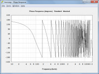
Phase is now shown wrapped exactly between -180 and +180 degrees.
BUG FIX
The phase wrapping point sampling bug reported in Post #8124 has now been fixed.
My thanks to TNT for helping to make Hornresp a better product.
Kind regards,
David
Hi Everyone,
CHANGE
Phase is now shown wrapped exactly between -180 and +180 degrees.
BUG FIX
The phase wrapping point sampling bug reported in Post #8124 has now been fixed.
My thanks to TNT for helping to make Hornresp a better product.
Kind regards,
David
Attachments
Hi guys
I posted here 2 weeks ago trying to get some help with using Hornresp. I was told this thread was for troubleshooting technical issues with the program. So I asked for my post to be broken off into a new thread.
I’ve refamiliarized myself as best as I can with Hornresp and have been trying to model my idea correctly, but I have questions that I don’t know the answers to and I’m not getting any feedback.
Basically, I’m trying to model a dipole driver arrangement with a waveguide attached to the front. If anyone with more experience with Hornresp could pop into my thread linked below and help me out I’d really appreciate it. Thanks.
Modeling dipole bass with waveguide?
Question, is a Bib modeled as an od tl with the driver 1/3 down the line?
Hi Etocynned,
The standard BIB loudspeaker is modelled in Hornresp as an offset driver horn. The optimum position for the driver can be found using the Loudspeaker Wizard tool.
Kind regards,
David
Hi M1 Audio,
I would normally interpret "a horn with serial duct" to mean a duct segment connected in series with a horn segment, either at the throat end or at the mouth end, as shown highlighted in red and green in the attached schematic diagram, but your throat adaptor comment makes me think that you may have something else in mind. Also, when you say "the Vtc camera", are you referring to the throat chamber perhaps?
As you can see, I am still a little confused.
Kind regards,
David
There's David ...
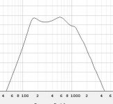
The port is inside the horn.
As you can see in the chart, it was simulated in your software. This is the response of two speakers
Attachments
There's David ...
The port is inside the horn.
As you can see in the chart, it was simulated in your software. This is the response of two speakers
Hi M1Audio,
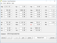
Thanks for the feedback. Would it be possible to post a screenprint of the Hornresp input parameters window for your design? It would be interesting to see how you modelled the system.
Kind regards,
David
Hi M1Audio,
Thanks for the feedback. Would it be possible to post a screenprint of the Hornresp input parameters window for your design? It would be interesting to see how you modelled the system.
Kind regards,
David
This box was not simulated by me. The way to configure the Hornresp to be able to simulate this design is precisely the mystery that I look for that somebody let me clarify here.
This box was not simulated by me. The way to configure the Hornresp to be able to simulate this design is precisely the mystery that I look for that somebody let me clarify here.
Hi M1 Audio,
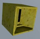
From the appearance of the cabinet, perhaps it was modelled as a "Horn-Loaded Vented-Box Enclosure With Port Exit Located Inside Horn Mouth", using the tapped horn option, as described in the Hornresp Help file?
The attached schematic shows such a tapped horn design. The horn is specified using three segments, the length of the first segment being 0.1 cm. The red dashed circle represents the front side of the driver diaphragm, facing into the horn. The green dashed circle shows the rear side of the driver diaphragm, facing into the rear chamber specified using Vrc and Lrc. The large black dashed circle is the rear chamber, and the small black dashed circle is the port tube from the rear chamber into the horn, specified using Ap and Lpt.
It would of course be better simply to ask the person who posted the design in the first place, but I guess it has not been possible to do this
.Kind regards,
David
Attachments

Hi Everyone,
CHANGE
Phase is now shown wrapped exactly between -180 and +180 degrees.
BUG FIX
The phase wrapping point sampling bug reported in Post #8124 has now been fixed.
My thanks to TNT for helping to make Hornresp a better product.
Kind regards,
David

Hi David,
Did you already tought about introduce simulation for Directivity Indeces in the hornresp?
Would it be possible? maybe Partial Directivity for single cab ?
https://www.princeton.edu/3D3A/Publications/Tylka_3D3A_DICalculation.pdf
http://www.dtic.mil/dtic/tr/fulltext/u2/778660.pdf
Did you already tought about introduce simulation for Directivity Indeces in the hornresp?
Would it be possible? maybe Partial Directivity for single cab ?
https://www.princeton.edu/3D3A/Publications/Tylka_3D3A_DICalculation.pdf
http://www.dtic.mil/dtic/tr/fulltext/u2/778660.pdf
Did you already tought about introduce simulation for Directivity Indeces in the hornresp?
Hi LORDSANSUI,
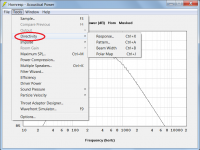
Hornresp has four Directivity tools - they can be used with a direct radiating single driver, a finite single-segment non-negative flare horn with no throat adaptor, or a port. Maximum coverage angle is +/- 90 degrees.
See the Help file sections on:
Directivity Response
Directivity Pattern
Directivity Beam Width
Directivity Polar Map
Kind regards,
David
Attachments
Dear Mr. McBean,
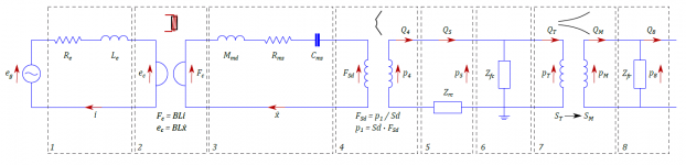
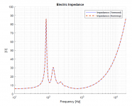
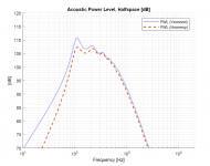
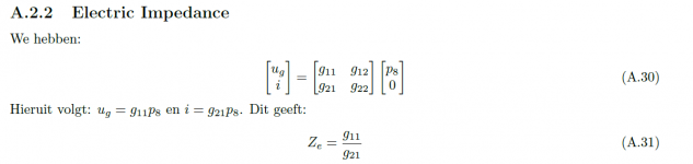
With the help of 'Acoustics', written by Leo L. Beranek and Tim Mellow, I've modeled a front-loaded horn. I have calculated the frequency response using transmission matrices. The diagram is shown in 'electric_equivalent_circuit.png'. When I calculate the throat impedance (Horn transfer matrix combined with the acoustic radiation of the piston (mouth area) in an infinite baffle), the results exactly match with Hornresp. So does the electric impedance of the total circuit. That's why I'm thinking the circuit and calculations are not that wrong. However, the acoustical power plot I can not reproduce, see the attachments.
I'm using the following equations:
W = p8^2 / Zfr
Wref = 2pi r^2 pref^2 / (rho*c) with (r = 1)
PWL = 10log10(W/Wref)
p8 can be found in the electric_equivalent_circuit.png.
Maybe you can shine your light on the above equations and maybe find an error in my calculations?
====================
Edit 3/18/2018, 9:23PM:
Maybe the calculation of p8 can still be wrong, since this variable is cancelled out with the calculation of the electric impedance, see attachment. Maybe the assumption that the front and rear chamber are modeled as pure compliance's is not correct?
Attachments
Last edited:
they can be used with a direct radiating single driver, a finite single-segment non-negative flare horn with no throat adaptor, or a port
Why not for TH and others designs?
Maybe you can shine your light on the above equations and maybe find an error in my calculations?
Hi Vermond,
The screenprint of your Hornresp input parameters window shows the Le label in red, which indicates that the Lossy Le option has been activated. The Lossy Le option needs to be turned off. The W = |(p8/Zfr)|^2 * Ra equation suggested by Bolserst is the one to use. If the results still don't match then it seems that there may be an error in the calculation of p8, as you have assumed. With the "resonances masked" option selected, Hornresp models the front and rear chambers as pure compliances.
Kind regards,
David
Why not for TH and others designs?
Multiple-segment horns would require finite-element techniques to be used, which would increase calculation times to unacceptable levels.
which would increase calculation times to unacceptable levels.
I think modern pc's can handle it nowadays
Or did you mean your brain can't handle the calculations

- Home
- Loudspeakers
- Subwoofers
- Hornresp