Multiple-segment horns would require finite-element techniques to be used, which would increase calculation times to unacceptable levels.
Is the Visual BASIC interface to slow? I remember your comments about the horn wizard and the inability to work with real horn contours versus conic stacks approximating the contour. We need turbo charged Visual BASIC!
Hi Bolserst and David,
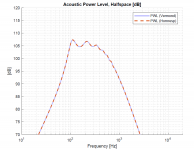
both your corrections did the trick. Thank you very much! See the attachment for two matching curves. Although this may sound silly, but I was struggling for some time now with this circuit, and these matching curves made me very happy") .
.
both your corrections did the trick. Thank you very much! See the attachment for two matching curves. Although this may sound silly, but I was struggling for some time now with this circuit, and these matching curves made me very happy
.Attachments
Hi M1 Audio,
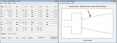
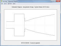
From the appearance of the cabinet, perhaps it was modelled as a "Horn-Loaded Vented-Box Enclosure With Port Exit Located Inside Horn Mouth", using the tapped horn option, as described in the Hornresp Help file?
The attached schematic shows such a tapped horn design. The horn is specified using three segments, the length of the first segment being 0.1 cm. The red dashed circle represents the front side of the driver diaphragm, facing into the horn. The green dashed circle shows the rear side of the driver diaphragm, facing into the rear chamber specified using Vrc and Lrc. The large black dashed circle is the rear chamber, and the small black dashed circle is the port tube from the rear chamber into the horn, specified using Ap and Lpt.
It would of course be better simply to ask the person who posted the design in the first place, but I guess it has not been possible to do this
Kind regards,
David
This way, good night David!
I thought about this possibility to simulate with an TH, but think a little about me ...
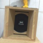
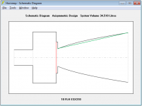
In the simulation that I want, the loudspeaker radiates directly into the air (direct radiation) along with the breather, passing through the throat until finally it reaches the mouth of the horn, this in a straight line. (Annex 1)
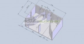
While on a TH (Tapped Horn) I understand that the loudspeaker sits at one end of the segment (coupled to the air) having somehow a manifold effect with the vent in series. (Annex 2)
Now I have a question:
The way the soft stuffed a TH would not be a little different from my goal? I do not know if you, David, have a deeper understanding of bugle boxes, but if at least I can better understand how Hornresp sees this alignment (with a lustration perhaps), I believe it will begin to clarify my path better.
Thanks in advance!
Attachments
Is the Visual BASIC interface to slow?
Visual Basic is certainly a lot slower than Fortran.
I experimented with using finite-element techniques in Hornresp some time ago, but found that it could take hours to produce a result, depending upon the upper frequency limit specified. In some cases it was necessary to leave the program running overnight.
I think modern pc's can handle it nowadays
Or did you mean your brain can't handle the calculations
My slide rule would have a nervous breakdown
.(Yes, I really do have a slide rule).
Hi M1 Audio,
As I understand it, you want to model a front loaded horn, but with a port tube extending from the rear chamber to the throat of the horn. The "extreme" tapped horn configuration I described is the closest you can get to that design using Hornresp.
This appears to be a question more about system design than Hornresp. I am not really in a position to comment on such issues.
Kind regards,
David
In the simulation that I want, the loudspeaker radiates directly into the air (direct radiation) along with the breather, passing through the throat until finally it reaches the mouth of the horn, this in a straight line. (Annex 1)
As I understand it, you want to model a front loaded horn, but with a port tube extending from the rear chamber to the throat of the horn. The "extreme" tapped horn configuration I described is the closest you can get to that design using Hornresp.
The way the soft stuffed a TH would not be a little different from my goal? I do not know if you, David, have a deeper understanding of bugle boxes, but if at least I can better understand how Hornresp sees this alignment (with a lustration perhaps), I believe it will begin to clarify my path better.
This appears to be a question more about system design than Hornresp. I am not really in a position to comment on such issues.
Kind regards,
David
Hello David,
Would be possible to get with you the equation for the standard hornresp PAR horn flare ?
With this rawly simulation a got a good results that I'd like to try to reproduce using 3 straight line segments at possible real build.
Thanks in advanced.
Marcelo
Would be possible to get with you the equation for the standard hornresp PAR horn flare ?
With this rawly simulation a got a good results that I'd like to try to reproduce using 3 straight line segments at possible real build.
Thanks in advanced.
Marcelo
Attachments
I'd like to try to reproduce using 3 straight line segments at possible real build.
Hi Marcelo,
Export the horn data for your 45 cm parabolic horn and note the cross-sectional areas at 15 cm and 30 cm.
(You should find the area at 15 cm to be 333.33 cm^2, and the area at 30 cm to be 566.67 cm^2).
3 segment design:
S1 = 100.00
S2 = 333.33
S3 = 566.67
S4 = 800.00
L12 (Con) = 15.00
L23 (Con) = 15.00
L34 (Con) = 15.00
The results will be effectively the same as those for your original parabolic horn.
Kind regards,
David
Attachments
Export the horn data
All day learning about some hornresp function. Thanks.
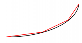
One think is strange to me is the visual feedback (Schematic Diagram), it indicates a kind of flare that isn't straight line (attachment #1 - black vs green), and this was the reason I asked for the equation, but checking the data after export, it's exactly a straight line (Y=aX+b) but it not correspond to the visual feedback. Is this right?
So when using PAR flare or CON one, the hornresp will use straight lines?
regards
Marcelo
Attachments

One think is strange to me is the visual feedback (Schematic Diagram), it indicates a kind of flare that isn't straight line (attachment #1 - black vs green), and this was the reason I asked for the equation, but checking the data after export, it's exactly a straight line (Y=aX+b) but it not correspond to the visual feedback.
Hi Marcelo,
The radius of a Par flare axisymmetric horn increases parabolically with axial length, as shown in the Hornresp schematic diagram. The cross-sectional area increases linearly with axial length.
The Y=aX+b straight line you plotted would have used the cross-sectional area data.
Because the cross-sectional area of a parabolic horn increases linearly, a rectangular horn with two parallel sides and two tapered sides will be a parabolic horn.
Even the legendary Paul Klipsch got it wrong in his original bass corner horn paper, when he described the initial front expansion as conical. He later corrected this to parabolic.
Kind regards,
David
Would be possible to get with you the equation for the standard hornresp PAR horn flare ?
Hi Marcelo,
To answer your original question
.Because the cross-sectional area of a parabolic horn increases linearly, the area Sx at any distance x from the horn throat is given by:
Sx = S1 + (S2 - S1) * x / L12
The radius Rx at any distance x from the horn throat of an axisymmetric parabolic horn is therefore given by:
Rx = (Sx / Pi) ^ 0.5
Kind regards,
David
Thansk David, but thinks still intriguing me 
The schematic diagram is composed by 2D lines, and a rectangular horn with two parallel sides and two tap
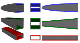
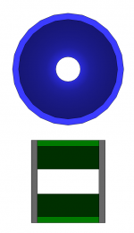
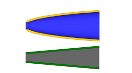
See the example below, 3 different horn flares, all of them with parallel sides (gray) and all of them generates rectangular coss-section area.
Leegend for the attachment #1
Yes, confirmed.
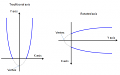
And parabolic things will follow the equation below.
Y = aX^2 + bX + c but what you plot is symmetric ay Y-axis with the vertex below S1 so I assume that the Schematic Diagram use the equation Y = aX^2 - c (with Y and X axis 90º rotated) - See attachment #2
Would you mind to clear?
Regards,
Marcelo
a rectangular horn with two parallel sides and two tapered sides will be a parabolic horn.
The schematic diagram is composed by 2D lines, and a rectangular horn with two parallel sides and two tap
ered sides can never generate a 2D parabolic projection, to project parabolic curve, the horn needs to be parabolic, or what hornresp is plotting is something different and it isn't a horn 2D projection as I'm supposing.See the example below, 3 different horn flares, all of them with parallel sides (gray) and all of them generates rectangular coss-section area.
Blue = Parabolic flare
Green = Taperad flare
Red = Constant flare
Leegend for the attachment #1
Left side = Perspective
Center = front view
Right side = Side view (what I was thinking that the schematic diagram is)
The Y=aX+b straight line you plotted would have used the cross-sectional area data.
Yes, confirmed.
And parabolic things will follow the equation below.
Y = aX^2 + bX + c but what you plot is symmetric ay Y-axis with the vertex below S1 so I assume that the Schematic Diagram use the equation Y = aX^2 - c (with Y and X axis 90º rotated) - See attachment #2
Would you mind to clear?
Regards,
Marcelo
Attachments
Hi Marcelo,
The Hornresp schematic diagram shows the side view of an axisymmetric (circular cross-section) parabolic horn. The radius increases parabolically and the cross-sectional area increases linearly. A rectangular cross-section horn will only be a parabolic horn if the area increases linearly.
While your blue example flares parabolically in one plane, it is not defined as a parabolic horn because the overall cross-sectional area does not increase linearly. Your green example is a parabolic horn because the cross-sectional area increases linearly. Your red example is not a parabolic horn.
Hornresp uses the two formulas given in my previous message to calculate the radius of the axisymmetric parabolic horn shown in the schematic diagram.
The defining characteristic of a parabolic horn is that the cross-sectional area increases linearly. The horn will only actually look like a parabola if it is axisymmetric (i.e. has a circular cross-section).
It can be confusing sometimes - as indicated earlier, it even caught out the great PWK.
Kind regards,
David
The schematic diagram is composed by 2D lines, and a rectangular horn with two parallel sides and two tapered sides can never generate a 2D parabolic projection, to project parabolic curve, the horn needs to be parabolic, or what hornresp is plotting is something different and it isn't a horn 2D projection as I'm supposing.
The Hornresp schematic diagram shows the side view of an axisymmetric (circular cross-section) parabolic horn. The radius increases parabolically and the cross-sectional area increases linearly. A rectangular cross-section horn will only be a parabolic horn if the area increases linearly.
See the example below, 3 different horn flares, all of them with parallel sides (gray) and all of them generates rectangular coss-section area.
Blue = Parabolic flareGreen = Taperad flareRed = Constant flare
While your blue example flares parabolically in one plane, it is not defined as a parabolic horn because the overall cross-sectional area does not increase linearly. Your green example is a parabolic horn because the cross-sectional area increases linearly. Your red example is not a parabolic horn.
And parabolic things will follow the equation below.
Y = aX^2 + bX + c but what you plot is symmetric ay Y-axis with the vertex below S1 so I assume that the Schematic Diagram use the equation Y = aX^2 - c (with Y and X axis 90º rotated) - See attachment #2
Hornresp uses the two formulas given in my previous message to calculate the radius of the axisymmetric parabolic horn shown in the schematic diagram.
The defining characteristic of a parabolic horn is that the cross-sectional area increases linearly. The horn will only actually look like a parabola if it is axisymmetric (i.e. has a circular cross-section).
It can be confusing sometimes - as indicated earlier, it even caught out the great PWK
.Kind regards,
David
Not sure that it makes things any clearer, but the description given in the book "Acoustics - Sound Fields and Transducers", by Beranek and Mellow states: "A parabolic horn can either have a rectangular cross section with two parallel straight walls and two non-parallel straight walls, or a circular cross section with a curved wall following a parabola."
"A parabolic horn can either have a rectangular cross section with two parallel straight walls and two non-parallel straight walls, or a circular cross section with a curved wall following a parabola."
Now everything is clear, Thanks you.
We have two different shapes that are equivalents if they respect the rule for the cross-sectional area to increase linearly with axial length.
The attachment is just illustrative but it represent the equivalents shapes
The cross-sectional equivalence is:
rectangular vs circular
The side view equivalence (axisymmetric)Tapared (linear) vs parabola (2nd order)
The equation hornresp use: Rx = (Sx / Pi) ^ 0.5 is a second order equation
Circular area (Sx) = Pi*Rx^2 that the general equation is Y = aX^2 - c (the c just move the curve up and down, it don't change the shape
- I like some algebra)Attachments
We have two different shapes that are equivalents if they respect the rule for the cross-sectional area to increase linearly with axial length.
Correct
.Can someone point me to tutorial about the file structure side of Hornresp...
for using Records, Import, Export, DataFiles, Editor, etc, ...
Hi Mark,
I am not aware of a tutorial that specifically covers the Hornresp file tools. Normally the average user doesn't worry about such things, as each individual design is automatically stored as a separate record in the default data file. A data file contains multiple records.
'File > Export Hornresp Record' enables the current design record to be exported as a separate file.
'File > Import Hornresp Record' enables an exported record to be imported into Hornresp.
'File > New' enables a data file to be created. This is sometimes done to archive groups of records, or to set up different data files for different speaker types, etc.
'File > Open' enables a saved data file to be loaded into Hornresp.
'File > Editor' enables records to be moved or copied from one data file to another, or for records to be deleted from a data file.
Kind regards,
David
Last edited:
- Home
- Loudspeakers
- Subwoofers
- Hornresp