Hi David:
I started simulating mids of synergy horns as offset drivers on conical horns before you implemented the multiple entry horn wizard so I have less experience with that wizard than I otherwise might. Recently I've been using it trying to correlate results of one method with the other. There is a significant difference that I'd like to discuss.
Take the Nd record and simulate normally and then compare the resulting power response to the Power1 result using the wizard for different values of offset entry port Ap1. The results agree with Ap1 when Ap1 is very small. As Ap1 increases a notch is introduced into the rising edge of the Power1 response. The notch grows in depth and frequency as Ap1 increases. What is happening?
Its easy to believe that the offset entry ports punch holes into the power response. The fact that the nulls seem to go all the way down to zero suggest a reflection off the ports and a resulting cancellation, similar to what goes on with the mids. As the ports get larger, the edge of the hole moves closer to the apex and so the frequency of the null increases. I think the simulated effect, or the effect on the acoustical power, is much greater than the effect on the SPL at any particular angle relative to the axis, especially those angles close to the axis that we might listen to directly.
I don't see that notch in measurements on my horn, although I'm measuring SPL rather than acoustical power. Some who have done detailed polar response measurements have reported off-axis anomalies that they attributed to the mid entry port holes. Tom Danley posted about the effect of the holes being mitigated by the shielding effect of being close to or in the corners of a rectangular horn.
All this being the case, I wonder if there is anything you can turn on or off or introduce a calibration knob to mitigate this effect. One way would be to allow the user to model the crossover based not on the Power1 response as now but on the acoustical power response created in a normal Nd simulation, not using the wizard, ignoring the mid port holes. A possible way to tune the simulation would be to use one Ap1 value for the Power2 response - that needed to optimize the mid output - and a different, knob-adjustable value for the Power1 response, the difference ostensibly modelling the shielding effect of the corners of the horn.
MrOil's thread in the multi-way forum is the immediate impetus for this post. I compared his results using the ME wizard to mine modelling the mids as offset drivers and realized the rather large difference in where the crossover would be was due to the notch shown on the leading edge of the CD's (Power1) response in the ME wizard. Because of the notch making it seem the CD couldn't go lower, MrOil chose a 2 Khz XO. The offset driver method suggests a 1400 Hz XO or lower, more in keeping with the rule of circumference at mid entry point being less than a wavelength at XO.
That was exactly what I needed, to get a picture of the relationship between files and records.
Hi Mark,
That was easily fixed
") .
.I suspected that the difference between Hornresp records and data files might have been the source of the confusion, which is why the sentence "A data file contains multiple records" was included in my response - in an attempt to clarify things a little.
Kind regards,
David
Hello David
I think I may have found a bug. When simulating a 6th Order Band Pass arrangement, in the design wizard enabling Lossy Le doesn't seem to do anything.
Thought you would like to know.
Thanks for everything you do!
Hi thejessman,
You have indeed found a bug - many thanks for reporting it!
It applies to the BP6, BP8 and ABC alignments, and will be fixed in the next release. The formula that calculates the modified value of Bl contains the ratio Le / Re, where Le is in millihenrys and Re is in ohms. I had inadvertently used Le in henrys.
The fix is as simple as changing Le / Re to (Le * 1000) / Re.
Thanks again for bringing this issue to my attention.
Kind regards,
David
Take the Nd record and simulate normally and then compare the resulting power response to the Power1 result using the wizard for different values of offset entry port Ap1. The results agree with Ap1 when Ap1 is very small. As Ap1 increases a notch is introduced into the rising edge of the Power1 response. The notch grows in depth and frequency as Ap1 increases. What is happening?
Hi nc535,
I would assume that the multiple offset driver throat chambers / entry ports are probably acting as a Helmholtz resonator frequency trap, but someone with more practical experience in these matters would know for sure. This is not really a Hornresp question
.Kind regards,
David
Hi Mark,
That was easily fixed
I suspected that the difference between Hornresp records and data files might have been the source of the confusion, which is why the sentence "A data file contains multiple records" was included in my response - in an attempt to clarify things a little.
Kind regards,
David
Hi David, you suspected right
Thanks again, for all you so graciously provide !
Very best, Mark
Hi nc535,
I would assume that the multiple offset driver throat chambers / entry ports are probably acting as a Helmholtz resonator frequency trap, but someone with more practical experience in these matters would know for sure. This is not really a Hornresp question
Kind regards,
David
Hi David:
That never occurred to me but after a little research and checking notch frequency behavior versus port length and area, I think that is exactly what is happening.
Knowing that and knowing that the notch doesn't appear in the near axis SPL tells me to ignore it when approximating an XO. I did that for MrOil and will show the results in his thread. Keeping the ports small and simulating a frustrum pushed the notch up above the XO transition range allowing good results.
Jack
Keeping the ports small and simulating a frustrum pushed the notch up above the XO transition range allowing good results.
Excellent
.@ David McBean
Hi, previously i'm sure that whilst moving the slider in the SAMPLE window, the data updated in real time with the position of the slider button, whilst still holding it down with a left click on the mouse.
If it's a bug ? it's not the end of the world, yet ! But i thought you'ld want to know. If it's not, my bad !
Excellent

To quote the only slightly nefarious Mr. Burns from the Simpsons.
@ David McBean
Hi, previously i'm sure that whilst moving the slider in the SAMPLE window, the data updated in real time with the position of the slider button, whilst still holding it down with a left click on the mouse.
If it's a bug ? it's not the end of the world, yet ! But i thought you'ld want to know. If it's not, my bad !
Hi Zero D,
Thanks for the feedback.
When the Sample slider bar control is dragged / scrolled using the mouse, the blue frequency value is updated but the actual sample results are not. The sample results are only updated when the mouse key is released. Because the results take a finite time to calculate, linking them to the 'scroll event' would adversely affect the smooth operation of the scroll bar. This is why they are only calculated when a 'change event' occurs.
If the mouse key is clicked and held down on the arrows at each end of the scroll bar, change events rather than a scroll event occur, and the data is continuously updated as the frequency changes, seemingly in real time. Clicking the mouse on the either side of the bar will also update the data in "real time", but with the frequency increment being ten times greater.
Kind regards,
David
To quote the only slightly nefarious Mr. Burns from the Simpsons.
.Dreaming about Hornresp in your sleep - now that's a worry...
ooh trust me it happens!

Hello David,
May I ask for a small change in hornresp?
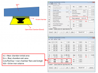
I've been simulating a cab design named Super Planar Top shared by Matthew Morgan J, and the results are very impressive in terms of output SPL vs cab complexity (you passed by that thread). One think I'd like to simulate is different flares in front of the driver but hornresp have some restrictions. Currently that design is simulated as OD and the "ressonator" is emulated using vented rear chamber with Vrc and Vtc = 0 + a big port, basically is like rear chamber being "opened" and hornresp has just one port flare (cylindrical, right?)
My proposal is to add another rear chamber type: Rear opened
Maybe, there are different ways to implement it, but as you can see in the attached image it wouldn't affect the current interface and all math already exist inside the hornresp.
10" top design - Open discussion
Thanks in advanced
Regards,
Marcelo
May I ask for a small change in hornresp?
I've been simulating a cab design named Super Planar Top shared by Matthew Morgan J, and the results are very impressive in terms of output SPL vs cab complexity (you passed by that thread). One think I'd like to simulate is different flares in front of the driver but hornresp have some restrictions. Currently that design is simulated as OD and the "ressonator" is emulated using vented rear chamber with Vrc and Vtc = 0 + a big port, basically is like rear chamber being "opened" and hornresp has just one port flare (cylindrical, right?)
My proposal is to add another rear chamber type: Rear opened
Maybe, there are different ways to implement it, but as you can see in the attached image it wouldn't affect the current interface and all math already exist inside the hornresp.
10" top design - Open discussion
Thanks in advanced
Regards,
Marcelo
Attachments
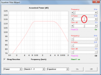
Very minor usability suggestion to save my clicking the same slider many times
change the default Q factor in the filter wizard from 0.01 to a more reasonable default. A sane default probably varies by filter type but I would guess ~0.7 is a reasonable default for shelf filters and high/low pass.
change the default Q factor in the filter wizard from 0.01 to a more reasonable default. A sane default probably varies by filter type but I would guess ~0.7 is a reasonable default for shelf filters and high/low pass.
May I ask for a small change in hornresp?
Hi Marcelo,
Seemlessly integrating the requested change would be not as easy as you might think
.I will have a look at the possibility, but only after the release of the next update - I have more than enough work to do already.
In the meantime, you can of course always use AkAbak...
Kind regards,
David
Very minor usability suggestion to save my clicking the same slider many times
Hi 3ll3d00d,
Drag the slider bar control (highlighted in red in the attachment) to somewhere near the value you want and then click on the bar either side of the control to adjust the value in 0.1 increments, or click on the arrows at each end of the bar to adjust the value in 0.01 increments.
Alternatively, when the slider bar has the focus, simply key in the exact value you want and press the Enter key.
Kind regards,
David
Attachments
- Home
- Loudspeakers
- Subwoofers
- Hornresp