Ok Guys, here is what I got. I had forgotten that I had another meter so I hooked it up inline with the +ve. When I set the pot to get 100mA then I read 12mv across the .33 resistors. This also gives me about 3.2V across Q7. If I raise the level to get 18mv across the .33 resistor I saw 130mA at the +ve and 3.4 across Q7. Unfortunately, my cheap meter started a little light show inside of it so it is no longer reading amps for me. My good meter quit that a long time ago. Looks like it is time to buy a new meter.
Anyway. I guess my question is what is the more accurate way to set the bias? Across the +ve, across the emitter resistors or across Q7?
Note. I tried using a one watt 100ohm resistor across +ve and Andrew was right. That 10V drop made a difference when it was removed.
Thanks, Terry
Anyway. I guess my question is what is the more accurate way to set the bias? Across the +ve, across the emitter resistors or across Q7?
Note. I tried using a one watt 100ohm resistor across +ve and Andrew was right. That 10V drop made a difference when it was removed.
Thanks, Terry
Last edited:
Are you getting the same 12mv across each pair of out puts? just readjust till it's the same then let the amp warm up and reset then seal the trim pot with a spot of nail polish or paint when happy with it's settings. Followed by a good sound test and it's ready..
regards A.
regards A.
Last edited:
I have it set right now at about 17mv across the emitter resistors. they re all off by a mv or two from each other. I am going to see about getting a new multimeter today.
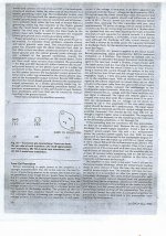
It is kind of hard to read the pic you posted, but it looks like he was suggesting 250ma of current. Looks like he was talking about class A. I don't think my PS or heatsinks will handle that much current. I already dropped a volt on the rails just setting it to where I am. Is that article about the Low TIM of the Superamp?
Thanks
it is still class AB, quiescent dissipation is a mere 42 watts with rails of +-85 volts, spread across 8 devices, about 5 watts per trannie, with the big heatsinks that Leach used, this is nothing much...
of course you can always bias your super leach at lower current say 40 to 50 mA per trannie...
the page i posted is about the original article, "Build a Double Barreled Amp" that appeared in the now defunct AUDIO magazine back in 1980...
of course you can always bias your super leach at lower current say 40 to 50 mA per trannie...
the page i posted is about the original article, "Build a Double Barreled Amp" that appeared in the now defunct AUDIO magazine back in 1980...
I'll probably leave it where it is for now. I looked back through some other threads and saw some claims that Leach recommended 125mA bias for the Superamp. I'm probably about there right now. I don't want to do any more testing until I get the channels that the T-03's are mounted in attached to the heatsinks.
On another point, my transformer is an Antek 8455 coupled with two 22,000uf filter caps. It is putting out right at +/-90V rails. Do you think I need more filter? This is more capacitance than Leach called for but he used 4 caps rather than two.
Thanks, Terry
On another point, my transformer is an Antek 8455 coupled with two 22,000uf filter caps. It is putting out right at +/-90V rails. Do you think I need more filter? This is more capacitance than Leach called for but he used 4 caps rather than two.
Thanks, Terry
22,000uf per rail is fine, I use 15000uf per rail on my 300 per channel amp with 70v rails with very good performance plus 6k8 and 220nf caps across them to drain after powering down the amplifier. I would recommend adding speaker fail safe circuitry is case faults happen and cook your speakers...
These type of circuits can be brought on line or if you want to make your own using small transformer even tap it off the amps psu.
My own amp has many fail protection circuits such as soft start/system ready/dc detection with 2 relays latching each channel plus clip display and thermal shut down...All seems over kill but amp is in local studio and I've seen first hand how gear is used by swapping speaker cabs when amps are powered up!
Regards A.
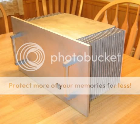
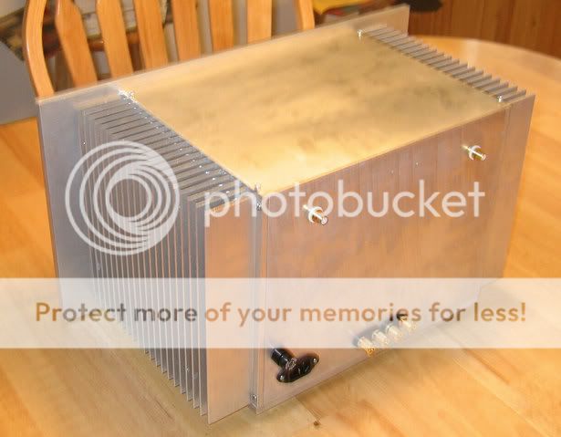
The chasis is too big for the low TIM. You can make a smaller chasis for low TIM and install your superamp in this chasis. Will put this chasis to correct use at a little extra work.
Not comfortable, then leave it for its resident amp.
Gajanan Phadte
The Low TIM that I built is done with Jan's PCB's which are quite large. Not that much of the case is unused.
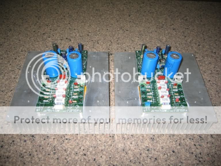
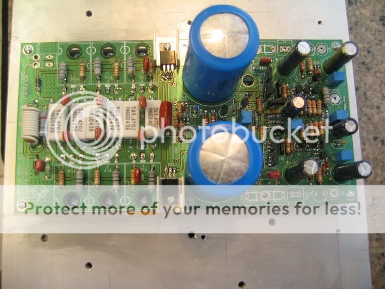
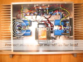
Those heatsinks were originally planned for the Superamp. I actually had the output channels mounted to them. When I couldn't get it working, I used them for the Low TIM. I have another pair just like them that I plan to use for the Superamp now. That is why I said it will probably end up looking like the Low TIM.
22,000uf per rail is fine, I use 15000uf per rail on my 300 per channel amp with 70v rails with very good performance plus 6k8 and 220nf caps across them to drain after powering down the amplifier. I would recommend adding speaker fail safe circuitry is case faults happen and cook your speakers...
These type of circuits can be brought on line or if you want to make your own using small transformer even tap it off the amps psu.
My own amp has many fail protection circuits such as soft start/system ready/dc detection with 2 relays latching each channel plus clip display and thermal shut down...All seems over kill but amp is in local studio and I've seen first hand how gear is used by swapping speaker cabs when amps are powered up!
Regards A.
I'm not sure how ambitious I will get with extra circuitry. I guess it will depend on how much I like the sound and what it gets used for. I have quite a stack of amps already.
When I first got in to DIY I was constantly searching Ebay for heatsinks because it seemed like all of the amps guys were raving about were Class A. The first amp I built was the P101 and I bought new heatsinks and they were very expensive. I bought used after that. I still have quite a few including some tunnels that are drilled for T-03's.
Andrew,
I am using On Semi MJ15003 and MJ15004. What would you say it the best starting bias for them? What voltage drop should I be looking for over the .33ohm emitter resistors?
Thanks, Terry
Andrew,
I am using On Semi MJ15003 and MJ15004. What would you say it the best starting bias for them? What voltage drop should I be looking for over the .33ohm emitter resistors?
Thanks, Terry
NP has a lot of inputs here: http://www.diyaudio.com/forums/solid-state/488-optimum-class-b-better-than-class-ab.html
workhorse thread: http://www.diyaudio.com/forums/solid-state/58561-low-biasing-high-biasing-class-ab-amps.html
streten's : http://www.diyaudio.com/forums/solid-state/191907-class-ab-being-mismaligned.html
workhorse thread: http://www.diyaudio.com/forums/solid-state/58561-low-biasing-high-biasing-class-ab-amps.html
streten's : http://www.diyaudio.com/forums/solid-state/191907-class-ab-being-mismaligned.html
- Status
- This old topic is closed. If you want to reopen this topic, contact a moderator using the "Report Post" button.
- Home
- Amplifiers
- Solid State
- Leach Superamp, round 2
