All great advice. I couldn't agree more. You can never be hasty about stuffing a PCB. Slow and methodological. Double check values and locations and you'll have much better chance at success - the first time. Doing it right the first time is easier then fixing it after the fact.Start fresh, keep all your earlier papers aside. Take the parts list and check all the resistors for their value using a DMM. Tick mark it on the list.
When I am assembling a board, I gather all the required parts and then assemble. This is needed for the resistors especially, as you will not miss the values and any mistake will show up when you find that the remaining resistors are of incorrect value. You can then find out your error and correct it.
Never have all your resistors' assortment at hand and assemble. Mistakes will be difficult to locate.
Gajanan Phadte
")
The devices showed up today and I had enough of the other transistors so I replaced all of them. I didn't match anything since I haven't a clue what I did with the circuit I built to test them. It will play a pretty clean signal at the output but there are still some issues. Still seeing about a 10V difference between the collectors of Q12 and Q13. If I check the + side of the circuit I follow a clean signal all the way to the end but the - side has a couple places where I lose it. Seeing about 2V offset on the output. I want to go over all the traces again tomorrow and make sure I don't have any breaks, cold joints or bridges. Once I do that I will post all the voltages and see if we can finally get to bottom of it. Getting real close now.
Oh, I almost forgot. One thing it is doing that is really weird. I am powering it up on a Variac. It will start producing a clean signal at about 30V rails. Stays pretty stable until about 77V. Any higher and it will all of a sudden go to about 66VCD on the output. If I back it down to 75V rails it will stabilize and the output will drop back down to about 2V offset and the signal will come back.
Thanks to everyone for their help.
Blessings, Terry
Last edited:
2 volts on the o/p is not good for your speakers and o/p voltage should be ac volts only plus it does seem to be your amp is going in to rail sticking where your getting such high off set readings.
I would recommend you build a dc protection as a add on circuit with relay cut off this will trigger if it 'see's' voltage over a volt or more and in doing so will save your speaker from damage via it's relay contact's opening quickly to cut speaker form amplifier o/p.
These circuits a common in most audio amplifiers and some use ic based circuity but simple transistor circuit can be built.
If you check your working module with full supply voltage and all is well there, next trace back from it's speaker o/p and long the feed back resistor right to the front tail i/p pair transistors where the feed back resistor meets there base leg....what is the volt reading here? in a working amp this will be in the mv range until signal is applied then raise up.
one thing have you got a fresh pcb as due to the amount of rework being done to the old pcb it will start to look rough..
2 volts on the o/p is not good for your speakers and o/p voltage should be ac volts only plus it does seem to be your amp is going in to rail sticking where your getting such high off set readings.
I would recommend you build a dc protection as a add on circuit with relay cut off this will trigger if it 'see's' voltage over a volt or more and in doing so will save your speaker from damage via it's relay contact's opening quickly to cut speaker form amplifier o/p.
These circuits a common in most audio amplifiers and some use ic based circuity but simple transistor circuit can be built.
If you check your working module with full supply voltage and all is well there, next trace back from it's speaker o/p and long the feed back resistor right to the front tail i/p pair transistors where the feed back resistor meets there base leg....what is the volt reading here? in a working amp this will be in the mv range until signal is applied then raise up.
one thing have you got a fresh pcb as due to the amount of rework being done to the old pcb it will start to look rough..
Yes I know 2v is too much. That is why I am still working at it.
No, I don't have any extra boards. I etched these when I first got in the hobby. I doubt I have the equipment and materials to do another.
Check whether NPN is NPN and PNP is PNP
What is the voltage drop across R11 and R12.
Gajanan Phadte
I tried to be very careful as I installed the new devices. I'm pretty sure they are all correct. Voltage drop across R11 is .5V and across R12 is .6V.
Have you checked the voltages across all the output stage resistors?
Thanks for stopping by Andrew. Please continue to help here. I need all the eyes I can get. The output stage is not in the circuit at the present.
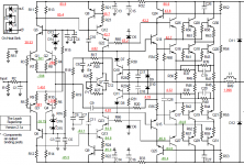
I was able to get the board to run at full rails so I took some fresh measurements. Please look at the attachment. Everything looks reasonably close until you get to the collectors of Q12 & Q13 It all kind of falls apart after that. Perhaps one of you can help me understand why there is 43.7V on the collector of Q12 and -84.8V on Q13. I used two different colors to hopefully help distinguish between the + and - readings.
Thanks again to all of you who are investing time for me.
Blessings, Terry
Attachments
All valid comments have been posted on this amplifier to try and get things working and as just outlined connect up the power transistors and see how things run, also you don't need to use the full supply +/- 90 odd volts to get this amp to operate even 50 to 70 is fine.
most of us when dealing with faulty amplifiers may use bench psu's and meter around things to see what's going on then when the faulty part(s) are replaced and final checks are done followed by dummy loads etc.
we all can see how this amplifier is testing and you feel your just banging your head off the wall saying oh f$$$ help running out of ideas here...we've all at some point been on this road.. once it's done and dusted break out the beer..
regards A.
BJT amplifiers work with current.
I require voltage drops across resistors (= current) for all the output stage resistors.
Remember I said you can operate without the final stage if you connect up the open circuit NFB.
Please give me the resistor numbers you need. I will be happy to measure them. Remember, Q18, 19 , 20, 21, 28, 29, 30 & 31 are not hooked up yet. Q7 is shorted and the Emitters from Q16 & Q17 are connected to the output. R61-64 are also not in the circuit.
I checked R52-55. They are all 6.2K and hooked up. For kicks, I lifted the bases on Q24 and Q25. The four resistors now all have the same voltage drop across each.Just looking at your latest voltage readings, it looks like R55 is either open or the wrong value. The lower half output stage is not dividing the voltage properly. The amp may operate this way, but not safely under load.
Here is a question. Could the +4.81V on the collector of Q23 be causing the high voltage on the Q23E/Q13C junction? Q13 collector and emitter are the same. I pulled Q13 and it tests fine.
Q12 has a .3V difference between Emitter and base and a 42V drop at the collector.
Q13 has a .7V difference between emitter and base and no drop at the collector.
I tested the circuit with Q13 removed and I still see almost rail voltage at Q23 collector so it is not coming from the base of Q23 and not from Q13. The base of Q23 actually measures higher than the collector.
Last edited:
Eureka! By Jove, I think I've got it!
I spent today pulling one transistor at a time and powering it up a taking measurements. No matter what I did, I couldn't get rid of the high voltage. Finally I sat with a pointed probe and for the 10th time went around every single trace and scratched a clear path. Well there must have been a tiny little solder bridge somewhere because at last it powered up clean and the two sides balance with each other. Offset at the output is mere 7mv. So I got brave and soldered up the power transistors and brought it up slowly on the Variac. .357V across the 100 ohm safety resistors and 11mv offset.
I hooked up the scope and see a perfect sine wave at the output. So I got brave and hooked up an 8ohm speaker and brought the sine wave generator up slowly. Clear sound but the safety resistor started smoking so I had to back it down.
Anyway, it's working. Now I have to set the bias and get the heatsinks bolted together so I can give it a good test.
Thanks to all of you for all the great help!
Terry
Congratulations
Congratulations on finishing it. can you please write the tensions end amplifier. regarding your last post.
Yes I know 2v is too much. That is why I am still working at it.
No, I don't have any extra boards. I etched these when I first got in the hobby. I doubt I have the equipment and materials to do another.
I tried to be very careful as I installed the new devices. I'm pretty sure they are all correct. Voltage drop across R11 is .5V and across R12 is .6V.
Thanks for stopping by Andrew. Please continue to help here. I need all the eyes I can get. The output stage is not in the circuit at the present.
I was able to get the board to run at full rails so I took some fresh measurements. Please look at the attachment. Everything looks reasonably close until you get to the collectors of Q12 & Q13 It all kind of falls apart after that. Perhaps one of you can help me understand why there is 43.7V on the collector of Q12 and -84.8V on Q13. I used two different colors to hopefully help distinguish between the + and - readings.
Thanks again to all of you who are investing time for me.
Blessings, Terry
Congratulations on finishing it. can you please write the tensions end amplifier. regarding your last post.
Last edited:

I just finished soldering up the second board. Weird, all the voltages look very close tot he other board but this board pulls about 2V across the 100ohm safety resistors. Maybe the bias is a little higher. I'll get into that when I get the rest done so I can begin adjusting. I'm just so stoked to finally have this thing running.
Yes, I fully intend to take measurements for all the devices and work up a schematic similar to what I have posted. This will have to be helpful for folks in the future.
Blessings, Terry
Congratulations on finishing it. can you please write the tensions end amplifier. regarding your last post.
Yes, I fully intend to take measurements for all the devices and work up a schematic similar to what I have posted. This will have to be helpful for folks in the future.
Blessings, Terry
Ok, I've got a question about setting the Bias. Dr Leach doesn't say what the bias should be on the Superamp so I am assuming we are to set it the same as the Low TIM. This is what he say in the Low TIM instructions.
"Remove F2 and clip an ammeter across the fuse terminals.
Power the amp up with no input signal or load. Adjust P1 for the channel connected to F2 for a current of 100 mA.....When the bias is adjusted properly, a dc voltmeter will read close to 3.4 V across Q7, i.e. across the collectors of Q12 and Q13.."
I don't have an ammeter that will go above 60V so I intend to use a resistor in place of F2. I want to make sure I am understanding Ohm's Law. If I use a 100ohm resistor, Should I adjust until I see 10V across the resistor?
10V/100R=.1A
Would it work just as well to measure the voltage across Q7?
Thanks, Terry
There a two ways the set bias on a amplifier, one being across the fuse holder and setting up current that way.. Remove the fuse and place meter in current mode with no resistor across the fuse holder and adjust the trim pot slowly to 100mv with no loading on the o/p and with the I/p shortedy to ground. Let the amp warm up and reset to 100mv. Second way is to place your meter leads between the emitter legs of the out put devices thus reading the volt drops over the emitter .47 / .33 ohms resistors.
- Status
- This old topic is closed. If you want to reopen this topic, contact a moderator using the "Report Post" button.
- Home
- Amplifiers
- Solid State
- Leach Superamp, round 2