Would agree we're an odd bunch..still some of us like to run amps with high bias to warm things up its just finding what suits you or the amp best!..
Take peavey amps they bais there pv 2600 amp at 20mv per pair of o/p this coming from pv's service department.
Read this info on amps lab site he sets bias at 100mv per device over the .33 ohm resistor (39 MV reading). More info in G randy slones book on setting up amps..
Regards .A
Take peavey amps they bais there pv 2600 amp at 20mv per pair of o/p this coming from pv's service department.
Read this info on amps lab site he sets bias at 100mv per device over the .33 ohm resistor (39 MV reading). More info in G randy slones book on setting up amps..
Regards .A
Wow, I just finished reading through all three links from post #119. I saw "optimum AB bias" mentioned several times but no one ever specifically said how to obtain it. Might as well call it unobtainium. What I did see was a lot of people suggesting that an AB amp should be biased so that it stays in Class A through normal listening levels. I suppose in an amp this powerful, that might be reached at a lower output % than with a less powerful amp. I have purchased a new ammeter so I will go back to setting the bias by reading across F2.
Thanks, Terry
Thanks, Terry
Last edited:
BJT amps when run at high bias would have less distortions,
unfortunately thermal runaway is a real possibility
even if you use humongous heatsinks..
i strive for the least amount of bias but sounds decent to be listenable...
Well, I'm not thinking high bias, per se, but I am hoping for more than just decent or listenable. I can buy that cheaply at just about any yard sale.
")
Wow, I just finished reading through all three links from post #119. I saw "optimum AB bias" mentioned several times but no one ever specifically said how to obtain it. Might as well call it unobtainium. What I did see was a lot of people suggesting that an AB amp should be biased so that it stays in Class A through normal listening levels. I suppose in an amp this powerful, that might be reached at a lower output % than with a less powerful amp. I have purchased a new ammeter so I will go back to setting the bias by reading across F2.
Thanks, Terry
Not 'Unobtanium', but you'd need to be able to measure THD to optimize bias settings for any given design. Generally the 26mV rule has served me very well, though I prefer to use that with 0R22 or 0R33 emitter resistors, I'd go lower with 0R10 to limit heating.
Not 'Unobtanium', but you'd need to be able to measure THD to optimize bias settings for any given design. Generally the 26mV rule has served me very well, though I prefer to use that with 0R22 or 0R33 emitter resistors, I'd go lower with 0R10 to limit heating.
My emitter resistors are 0R33. I'll try the 26mV and see what that gives me over F2.
Thanks
Most Diyer's on here ask for help with amplifiers to solve the nagging problems that there encountering with a giving item that's driving them to head bang the wall...
next is the more experienced tech who needs a fresh option from fellow engineers on a fault so we each give advice based on our years of service in the trade to aid repair..
The thing is about audio amplifiers we build them or repair a knackered amplifier from the pile in the conner......next we want to put said amplifier on full test and measurement to see it's over all performance such as thd or fq responses over the audio band of 20hz to 20khz.. most labs have test gear from top of the range distortion analyser's oscilloscopes to audio generators some Diyer's don't these so have to make with basic items.
In a nutshell we all have different ways to correct faulty equipment it's just up to us to find our way on the subject with information given..
Regards A.
As both of you have probably deduced, I am no amp tech. I am a retired construction superintendent/musician who enjoys building and learning. Each time I have had issues with something I've built, I learn something new. I have also learned quite a bit from reading about others' issues with their builds. It is my hope that others will be able to glean some help from this thread in the future.
Thank you for offering your insight into my troubles here. You have been very helpful and I feel like I have learned a lot.
Blessings, Terry
Thank you for offering your insight into my troubles here. You have been very helpful and I feel like I have learned a lot.
Blessings, Terry
My definition of optimum bias is to adjust for lowest distortion, preferably on an oscilloscope display of THD products to minimize high order distortion products, while not causing the amplifier to run excessively hot.
This also helps to determine the noise floor, hum, RFI/EMI ingress and possible oscillation; it may alert you to small but significant problems. I'm testing one of my Leach amplifiers right now with ThermalTrak transistors and I'm not entirely pleased with the noise floor nor with distortion at higher power and higher frequencies. Probably not caused by the output transistors. I'd like to be able to take full advantage of those fast perforated emitter transistors.
This also helps to determine the noise floor, hum, RFI/EMI ingress and possible oscillation; it may alert you to small but significant problems. I'm testing one of my Leach amplifiers right now with ThermalTrak transistors and I'm not entirely pleased with the noise floor nor with distortion at higher power and higher frequencies. Probably not caused by the output transistors. I'd like to be able to take full advantage of those fast perforated emitter transistors.
I got a hold of acenovelty. He said he runs his Superamp at 160mA so I'm giving that a try. I have had if playing for a couple hours and the heat isn't really an issue at all. The emitter resistors are at about 20mV. They are more closely matched at this current. The high-end is smoother than it was. I don't have r50 and c25 in the circuit right now. That will probably make a difference too. I will hook those up and report back.
My definition of optimum bias is to adjust for lowest distortion, preferably on an oscilloscope display of THD products to minimize high order distortion products, while not causing the amplifier to run excessively hot.
This also helps to determine the noise floor, hum, RFI/EMI ingress and possible oscillation; it may alert you to small but significant problems. I'm testing one of my Leach amplifiers right now with ThermalTrak transistors and I'm not entirely pleased with the noise floor nor with distortion at higher power and higher frequencies. Probably not caused by the output transistors. I'd like to be able to take full advantage of those fast perforated emitter transistors.
I have an audiophile friend who owns half a dozen ML-25's, one time he showed me how they calibrated the amps using extender boards, a function generator and a THD meter. He makes sure that his amps are within the manufacturers specs....he even has a staff of engineers that looks after this things, this audiophile friend of mine owns a commercial radio station....unfortunately, such facilities are not accessible to the average diy'er....
so biasing to get a bigger class A window without the possibility of thermal runaway is a step in the right direction...
The minute details in higher frequencies will improve considerably if you replace the zeners with a shunt regulator. Is is a big circuit compared to the two zeners and the caps across it, but it is worth.
Gajanan Phadte
i think the question was raised before, also why the ltp needs to sit at 40 volts....
i am trying to get my friend to simulate with voltages as low as 12 or 20...
the top of the cascode can use a higher voltage trannie with better specs, but this is for another thread, maybe you would like to open up a new one...
OK, so more fun.
I have been listening for a few hours and the sound is fairly nice. However, today I cranked up the volume a little and heard some distortion in the left channel. So I stopped and hooked up my sine wave genny and the scope and the right channel reads really good at all frequencies that I could test. I don't have a dummy load so I was the dummy sitting in front of my speakers for all of this.
Anyway I hooked up the left channel and I don't have to get it real loud before I see this.
1K
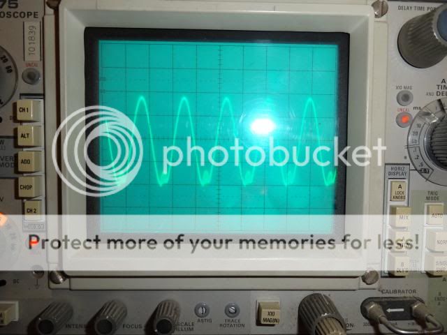
800hz
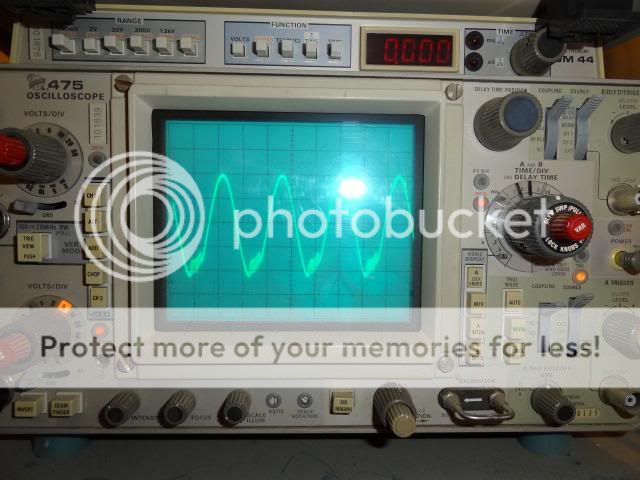
640hz

500hz

Another thing of note. The left channel is the one that I changed out all of the transistors. I know that originally, I had matched them but because of lack of equipment and due to my haste, I just put them in as they came out of the bag. This channel also has 034mv offset while the right channel has 007mv offset.
Can you guys give me somewhere to look?
Thanks, Terry
Last edited:
Quick and easy way to build a test load is buy some metal clad resistors say 200w or more at 4 ohm then link up to make 8 ohm next bolt them to a large heat sink this will save roasting your speakers. Your need to bring up the genie o/p to 1.2v ac to the amps input and scope things out. Are all volts the same at each point in the circuit? Check round the input pairs and around the vas drive stage(voltage amplification stage) vas..
Question at what level did things start to distort? Set your meter to ac and hook to the o/p and bring up slow., ie at 20 volts ac your amp is duing 50w @8ohms...
Regards A.
Question at what level did things start to distort? Set your meter to ac and hook to the o/p and bring up slow., ie at 20 volts ac your amp is duing 50w @8ohms...
Regards A.
here's one... 8 Ohm 200W Non-Inductive Dummy Load Resistor 019-030
you can check your small protection trannies...
you can check your small protection trannies...
Oscillating - in the usual way for stacked output stages. Compensating this out is VERY layout dependent - what works for one builder may not work for the next. What I did on mine (bigger amp, but similar output stage) was hang a 10k from emitter of Q26 to emitter of Q27, and 18K from emitter of Q24 to emitter of Q26. This forces the slave stage to always conduct a minimum amount of current, i.e., never cut completely off. The abrupt transitions in current along with the capacitive load of the output stage can generate negative resistance which causes what is known as a parametric oscillation. They suck, they're hard to model, and are usually fixed by experiment. You may have to play with the values of your base stopper resistors on the outputs, include them on the driver stage as well, and/or experiment with the values of R60 and C28. In one case I ended up hanging zobels from the emitters of the slave stages as well. In class H where the upper stage switches you ALWAYS need to do that.
I need to set up a circuit for testing transistors again. Leach suggests this one.
 . Can +/- 12VDC work instead of 15?
I have ordered one of these to use as a dummy load.
C300K8R0E Ohmite | Mouser
I read somewhere that they will work if mounted to a heatsink.
Thanks, Terry
 . Can +/- 12VDC work instead of 15?
I have ordered one of these to use as a dummy load.
C300K8R0E Ohmite | Mouser
I read somewhere that they will work if mounted to a heatsink.
Thanks, Terry
- Status
- This old topic is closed. If you want to reopen this topic, contact a moderator using the "Report Post" button.
- Home
- Amplifiers
- Solid State
- Leach Superamp, round 2