fan cooling is a must and will enable the load to take more than rated...also add caps for ac coupling, there's plenty of site's to choose on building plans plus add binding posts for quick connections even vu meters etc... these's are valid pieces of equipment and will last for many years.
check rod Elliott's audio page for building one...
check rod Elliott's audio page for building one...
i think the question was raised before, also why the ltp needs to sit at 40 volts....
i am trying to get my friend to simulate with voltages as low as 12 or 20...
the top of the cascode can use a higher voltage trannie with better specs, but this is for another thread, maybe you would like to open up a new one...")
IMO, the noise induced by the zener that corrupts the lower levels in the signal reproduces clean with a clean shunt regulator.
Gajanan Phadte
OK, I'm hoping that my problem is unmatched Q1-Q4 transistors. I'm trying to set up a jig to match them. In the circuit in post #140, may I assume that it is using a center tap power supply where in the NPN circuit the collector is connected to the +15V tap, the emitter, via an 8K2 resistor, is connected to the -15V tap and my ammeter is between the base of the transistor and the center tap? If this is true, can I use something different than an 8K2 resistor if I vary the voltage a little? I don't have any 8K2 resistors handy.
Use your working channel to narrow down defective transistors...also use your scope to check around the i/p pairs plus driver stage. double check all resistors to ensure correct ohmage...
There will always be a slight different reading between amplifier offsets some be as hight as 100mv or as low as 14mv etc...check around the bias circuit, driver stage also scope the o/p with no load do you still get the same wave form?
try is resistor combo value 6k8 plus 1k5 will be 8k3 ohms or two 10k parr =5k plus 3k3=8k3 near to what you need.. and connect meter as shown in test circuit..
Regarding using the matching transistor circuit... When using these circuits to match transistors, the power supply voltages should be held constant. Don't turn the voltage down or off when changing transistors. If the measured current appears to be unstable, the transistor may be oscillating or picking up a RF signal. In this case, a 0.1 ufd capacitor from base to emitter should cure the problem. You may notice some temperature drift of the current as the transistors warm up. You can use 9 V batteries in place of the 15 V sources if you change the 8.2 kohm resistors to 4.7 kohm.
If you do not have a multimeter that reads microamps, you can put a 51 kohm resistor in series with the base and measure the voltage across the resistor. Matched transistors will have equal voltages. The expected voltages should be in the approximate range of 0.2 V to 1 V.
Hope this clears things up a little..
OK, I guess I'm not understanding the circuit for testing the transistor. I took Andrew's advice and hooked up a 55+55Vac 300VA transformer through my Variac and used a 35A bridge. I set the variac so I have +/-15Vdc. I hooked up a couple resistors that give me 8K25 in line with the +15VDC and clipped that to the emitter of one of the NPN transistors. I hooked the -15VDC to the collector and then my amp meter between the base and the center tap of the transformer. I see no current. I checked for voltage and see -11.9VDC at the base but no current. What am I doing wrong?
I'm sorry, I did say that before but it was because I hadn't noticed that it had an attenuation switch. With no attenuation it puts out 1.6VAC. I'll hook it up again and get some readings at the input and output to show what voltage it starts clipping.
Thanks again, Terry
Still4given did you say that your signal genie only put's out 200mv? if so plug this in to a pre-amp to boost the signal to a ac reading of 1v, even some amps state 750mv i/p for a given o/p.
Regards A.
I'm sorry, I did say that before but it was because I hadn't noticed that it had an attenuation switch. With no attenuation it puts out 1.6VAC. I'll hook it up again and get some readings at the input and output to show what voltage it starts clipping.
Thanks again, Terry
I guess you can't edit after a given amount of time. I figured out the transistor test. I guess my ammeter just won't read that low. I used the 51ohm in series with the base and was able to get a reading. I have matched a few. The directions call for matching Q1 with Q3 and Q2 with Q4. Mine are all too far off for that. The NPN's are all in the 320-370mV range and the PNP's are in the 260-290mV range. I only have about 25 units each.
I am going to install the ones that are closest and then retest. Hopefully that will correct the oscillation problems.
Blessings, Terry
I am going to install the ones that are closest and then retest. Hopefully that will correct the oscillation problems.
Blessings, Terry
Evening Terry,try using your meter's hfe transistor checker just pop them in and it will give a reading say 543 or so then test a second transistor to get close enough say 553.. some meters have this function on the top right hand conner saying npn with bce and pnp bce..doese your meter have this as it would save using the tester circuit.
If you carry out the in and o/p test on the amp leave off the speaker load for now as a 1k tone at high level will have you reaching for the ear plugs..
Using your working module check for even o/p clipping and note the ac voltage on the o/p no load and this will be the max o/p at clip next back it off till a even sine wave is seen on your scope.
Just to add if you want to hear things add a 47 ohm at 50w or more on the o/p plus hook your speaker up as well this way you can hear the tone.
Regards A.
Last edited:
Hi A,
Yes my meter has HFE. For some reason, I thought Dr Leach didn't think that was sufficient for matching. I will check that as well.
Sorry I forgot to do the test you asked for. I just did it.
First, if I run the test with no speaker connected, it doesn't clip. I can run the Sinewave genny to 1.56VAC and the output is clean and at 33.9VAC.
Then I hooked up a speaker and ran it up and at about 1VAC at 1K it starts clipping. O/P is about 23VAC.
Now for the weird part, I just went back out to double check the numbers and I plugged in the speaker again and it didn't clip. All the way to 1.56V input 33.9V o/p, no clipping. I think I have a ghost in my amp. I'm still going to change out the front end transistors just because I didn't match them but I have no clue why all of a sudden the clipping went away. Maybe something is micro-phonic and picking up the speaker output. Weird!
A quick number crunch and your amp is doing 143w... o/p v divided load say 8 = current of 4.23 times volts out = power 143.65125.. round it off to 145w.. do the same with 4 ohm load = 33.9 divided 4 ohm = current of 8.475 then times by 33.9 = 287.3025..say to 290w.
That 1.56 is a little up try 1.2 volts..
That 1.56 is a little up try 1.2 volts..
No twisting of lines except for the wires going to the O/P devices. Power lines are just run across the table to the boards right now. Once I get it in a case I will tidy everything up. I have been playing it hard for about ab hour now and I can't get it to clip again. Now that I think about it, it did sound like feedback as if a mic was too close to the speaker. The weird thing was that it only showed on the bottom part of the signal. That has to mean something. It's not doing it at all right now. I have two cabinets per side plugged in so it is running in 4ohm. The bass is rather impressive!
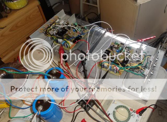
As being tested
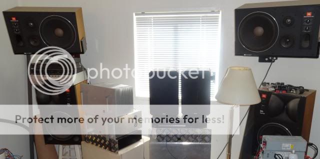
JBL torture stacks
As being tested

JBL torture stacks

There were only a couple ways I could think of to shorten the wires. One would be to turn the boards at 90 degrees to the heatsinks or mount the boards directly above the O/P's The first method would make the case really wide to make room for the Tx and caps. The second method would require attaching the wires from the bottom of the PCB. I didn't want to attempt that because it would weaken the traces as well as be difficult to solder. As it is, I cut each wire as short as possible with the board right beside the O/P's.
On another note, the board that was clipping runs a lot cooler than the other channel. It is barely warm to the touch. The other doesn't run hot at all but is noticeably warmer than the one that was clipping. They are both biased the same and each of the collector resistors measure about 18mV on both sides.
On another note, the board that was clipping runs a lot cooler than the other channel. It is barely warm to the touch. The other doesn't run hot at all but is noticeably warmer than the one that was clipping. They are both biased the same and each of the collector resistors measure about 18mV on both sides.
- Status
- This old topic is closed. If you want to reopen this topic, contact a moderator using the "Report Post" button.
- Home
- Amplifiers
- Solid State
- Leach Superamp, round 2