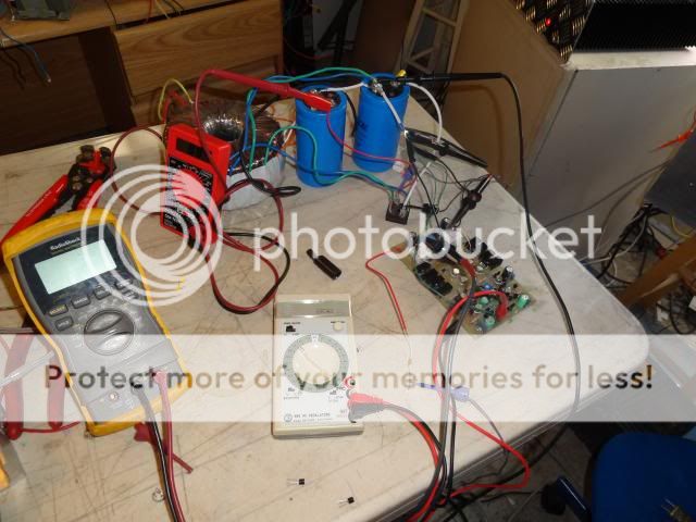
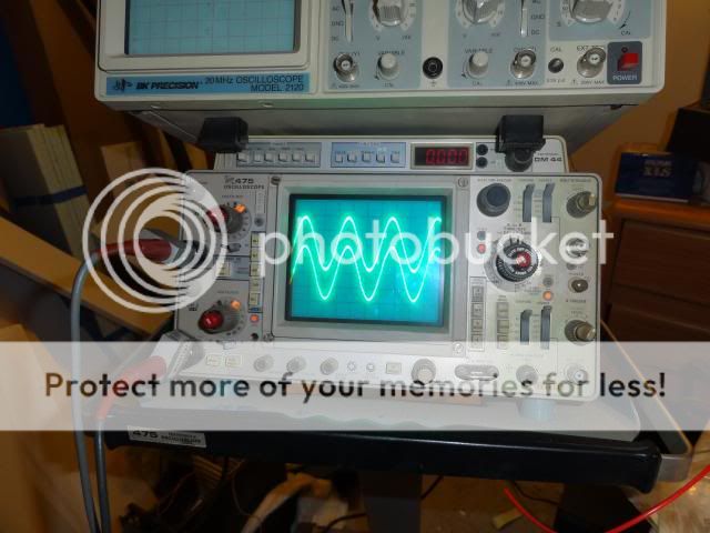
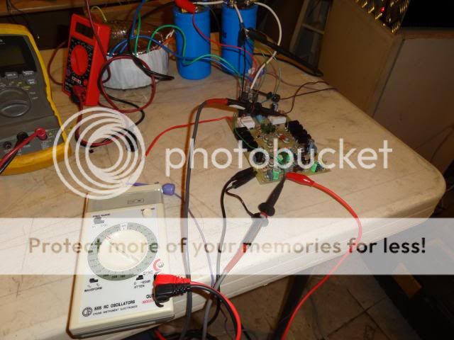
I still haven't found the problem with one of the boards but I got tired of waiting for my scope probes to arrive so I got out my strobes and amazingly my old Tech 475 came bac to life. I don't know for how long but at least it worked today. I got a chance to test the good board with a 1k Sine wave and it looks good so I will be hooking up the power transistors and give it try. Here are a couple of pics of the test today.
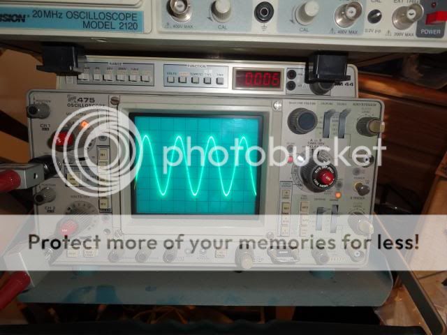


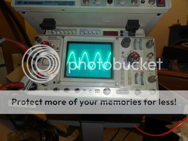
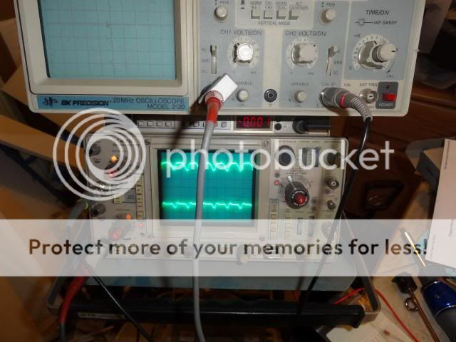
My Sine wave generator only puts out 140mV. That pic is of it at full output. I will probably have to use a preamp with it. I did another test with channel #1 on the input and channel #2 on the output. The first pic is an overlay of the two and the second with them separated. The output is on the bottom.


They both look the same good and clean now, 140mv is about the same as using a mic signal input and bumping things to say 860mv would be fine. What volt gain did you see at the out put of the module?
I don't know how to check for that. Could you please explain?
Will do.Have a look at turning the beam brightness down a bit.
the gain of the super leach is about x30 on the later versions...so that 140mv x 30 is about 4.2volts rms...what is the peak to peak reading on your scope?
you can divide that by 3 to get a quick equivalent rms...
in your case 4.2 volts rms is about 13 volts peak to peak....
mine are just quick estimates, your actual readings may be close to it...
you can divide that by 3 to get a quick equivalent rms...
in your case 4.2 volts rms is about 13 volts peak to peak....
mine are just quick estimates, your actual readings may be close to it...
Hopefully the 'scope will keep working so you can try some signal tracing on the non-working board.
Can you do add/invert with the two 'scope inputs? Sort of a rough distortion analyzer that way. So far as I can tell, my HP 'scope won't do that but I've got a Tek AA501A distortion analyzer for that anyway (not to mention my old Heathkit meter)
Can you do add/invert with the two 'scope inputs? Sort of a rough distortion analyzer that way. So far as I can tell, my HP 'scope won't do that but I've got a Tek AA501A distortion analyzer for that anyway (not to mention my old Heathkit meter)
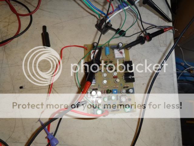
Yesterday, I tried swapping the devices around since I didn't have any spares. I ended up with almost rail voltage on the output so I have pulled all of the T0-3's out and have ordered new. When they get her I will carefully install and check the whole board for Solder bridges and cracked traces once again. The poor traces are getting a little haggard around the solder points since I have removed and replaced so many times. I may have to do a little point to point before I'm through.
You can run the amp without the output devices.
But you must connect up the NFB that is left open circuit.
The drivers will drive a high impedance load. start with 10k @ ~250mW, then try 1k @ ~2.5W.
The drivers should stay stay at their quiescent temperatures when outputting such low currents.
But you must connect up the NFB that is left open circuit.
The drivers will drive a high impedance load. start with 10k @ ~250mW, then try 1k @ ~2.5W.
The drivers should stay stay at their quiescent temperatures when outputting such low currents.
The replacement parts should be here Monday or Tuesday. Once I get them installed I can hopefully get to the bottom of it. If the board works I will go ahead and attach the output devices and do a proper test. Hopefully I can finish it up then. I will work up a schematic with all the voltages marked for future use.
Hopefully the 'scope will keep working so you can try some signal tracing on the non-working board.
So far it is working fine. I know very little about using a scope. I was tickled that I got it working well enough to take the pics. I'm going to watch some tutorials and see if I can learn more about them. Seems like a useful tool for this stuff.
Hopefully the 'scope will keep working so you can try some signal tracing on the non-working board.
Can you do add/invert with the two 'scope inputs? Sort of a rough distortion analyzer that way. So far as I can tell, my HP 'scope won't do that but I've got a Tek AA501A distortion analyzer for that anyway (not to mention my old Heathkit meter)
So far it is working fine. I know very little about using a scope. I was tickled that I got it working well enough to take the pics. I'm going to watch some tutorials and see if I can learn more about them. Seems like a useful tool for this stuff.
I just read my post above and realized I typed the wrong number for the transistors. What I pulled and ordered new of are the T0-39's. 2N5415 and 2N3439 to be exact. Should have them Monday. I talked to a friend at the flying field today who is a retired EE. He has offered to help me hands on if necessary so looks good to get this thing up and running.
I took a little diversion today since I am waiting on parts. I built a Symasym version 5 I think. Right as I was finishing it up, they came out with a version 5.3 that you could buy factory made boards for so the first one got stuck on the shelf and I built another one with the new boards and finished it case and all. well the original was staring down at me so I pulled it down and hooked everything up. How bout that, it plays. As a matter of fact, it sounds unbelievably nice considering it is all hooked up with 22ga jumper wires.


Still4given, your o/p devices are ok so no need to replace them, if you've got rail voltage at the out put of your amplifier it's gone dc common fault for this is imbalance input diff stage or vas stage recheck the small tail input transistors..
One thing if you've resoldered the circuit board over and over again how is the tracks looking? As this can add to the problem.
One thing if you've resoldered the circuit board over and over again how is the tracks looking? As this can add to the problem.
Q7 has same voltage on collector as well as emitter. Either tere is a short or the transistor is defective.
If in the process of assembling, if you had fitted any of the transistors wrongly and powered the circuit, then you should replace all of them if you do not remember which one.
Check whether the transistors are properly installed.
Gajanan Phadte
Congratulations, you are finally on the right path.
Gajanan Phadte
What does that mean?Congratulations, you are finally on the right path.
Gajanan Phadte
It means when an assembled circuit is not working, you have to make it work by finding the fault and the design performance can be evaluated later. No job for CRO or a genie till it works. This is not the case for a fault develooped later, on a working unit as mostly one component will go faulty. Multiple failures and wrongly connected devices cannot be analyzed by any test equipment. DMM is the best coice.
Gajanan Phadte
Gajanan Phadte
- Status
- This old topic is closed. If you want to reopen this topic, contact a moderator using the "Report Post" button.
- Home
- Amplifiers
- Solid State
- Leach Superamp, round 2