You can connect the big caps straight away. One advantage of the bulb in series with the mains, is it will allow those caps to charge somewhat slower than normal. This will help recondition them.
I don't expect you'll have much problem with them - switch on and measure the voltage across them, you should see a nice stable voltage. Remember to discharge them after you power off for safety.
I don't expect you'll have much problem with them - switch on and measure the voltage across them, you should see a nice stable voltage. Remember to discharge them after you power off for safety.
You can connect the big caps straight away. One advantage of the bulb in series with the mains, is it will allow those caps to charge somewhat slower than normal. This will help recondition them.
I don't expect you'll have much problem with them - switch on and measure the voltage across them, you should see a nice stable voltage. Remember to discharge them after you power off for safety.
I connected 1,2,3 for the big caps plus 9,15 for the ground and the secondaries from the tranny... When I start the amp the bulb turn on

R14 is used as a voltage drop device, for the soft-start relay (S/S) ckt, S2, this must be there and operational, i.e.-24V at terminal "4" to close the relay shortly after the mains switch is closed. If it is not working properly, the S/S resistor R1 will over-heat and if left for very long, a minute or two, it will blown the thermal fuse "*FUSE" 10A.This is a safety feature!!
The BIG caps should have not been hooked/wired up until this S/S ckt was proven to be operational first!!
Rick
The BIG caps should have not been hooked/wired up until this S/S ckt was proven to be operational first!!
Rick
So all the PS voltages are correct per the schematic? Then follow what i said previously, test out all the other pcb assemblies, and lastly start on one of the PA channels at a time.Ok everything fine 68v after the caps...
What should I do next?
Rick
R14 is used as a voltage drop device, for the soft-start relay (S/S) ckt, S2, this must be there and operational, i.e.-24V at terminal "4" to close the relay shortly after the mains switch is closed. If it is not working properly, the S/S resistor R1 will over-heat and if left for very long, a minute or two, it will blown the thermal fuse "*FUSE" 10A.This is a safety feature!!
The BIG caps should have not been hooked/wired up until this S/S ckt was proven to be operational first!!
Rick
I disconnected R14 as suggested in order to not blow R26. At the moment I didn't connect the relè board, the only thing connected to the power supply board is the groung (9,15) and the caps (1,2,3)
So If I understanded right now I have to connect R14 and connect all the pin on the power suplly, then test the amp with all board on except fot the 2 output channel, if everything is right I should start testing one channel at the time
I'm not sure where you are up to now.
Backtrack, disconnect R14 and recheck all is OK
I tried something different, I left R14 in and connected only 1,2,3,9,15 to the power supply. Evrything fine, 68v out of the big caps
If I connect the other boards (except output) the bulb turn on
If all the PSU voltages are OK then we can move on to testing one channel. This is where you must not run ahead but must be methodical and careful.
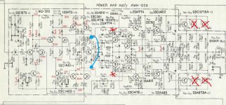
Each channel uses 3 pairs of output transistors. We are going to build the amp using just ONE pair initially. The protection circuitry is going to be disabled and the vbe multiplier disabled to force the quiescent current to zero assuming there are no problems.
The circuit shows what to do. You link TR11 and D6 out as shown. D11 and D12 are removed. And you remove two of the three pairs of outputs, which ever pairs are easiest.
Measure the transistors first or better still, if the good channel has originals use a pair of those. Check the 0.5 ohm resistors that connect to the output transistors are OK (not open circuit or high in value)
Attachments
I tried the board in better condition... the bulb stayed all the time sligthly on and the voltage after the caps took longer to grow, it stop at 53V
I suppose there is something wrong with the board and probably it's time to look for transistors substitutes
EDIT: sorry I just read your reply, I will do as suggest tomorrow thanks for the help
I suppose there is something wrong with the board and probably it's time to look for transistors substitutes
EDIT: sorry I just read your reply, I will do as suggest tomorrow thanks for the help
That should be enough to be going on with. Make absolutely certain that you have the four supplies correctly wired and also the two grounds.
You can leave the input (pin 1) floating. It might be advisable to also link out (short) R1, the 820K to prevent any stray pickup and noise affecting things.
With the amp in this state the bulb should still be dim/out. The DC output voltage of the amp measured on L1 (extreme right of circuit) should be 0.00 volts give or take a few millivolts.
To test the power amp the auxiliary supplies are not needed so leave out R14 unless you have it all coupled up to the relay. That supply appears to only power the slow start relay.
If all the PSU voltages are OK then we can move on to testing one channel. This is where you must not run ahead but must be methodical and careful.
Each channel uses 3 pairs of output transistors. We are going to build the amp using just ONE pair initially. The protection circuitry is going to be disabled and the vbe multiplier disabled to force the quiescent current to zero assuming there are no problems.
The circuit shows what to do. You link TR11 and D6 out as shown. D11 and D12 are removed. And you remove two of the three pairs of outputs, which ever pairs are easiest.
Measure the transistors first or better still, if the good channel has originals use a pair of those. Check the 0.5 ohm resistors that connect to the output transistors are OK (not open circuit or high in value)
I tried to follow instructions, I'm not shure if I had to remove Q11 or not. Secondly I didn't understand where to measure L1.
About the output transistors none is original so I will start with two motorola 2N6030 since they seem in better condition.
One more question how do I measure if the transistors are working right?
Attachments
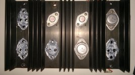
You've only got one side of transistors there. You need one transistor in the LEFT hand socket, and one in the RIGHT hand.
Can you list what transistors are installed on the big heatsinks? Let's see if you've got anything decent in the set to try with...
2x 2N6030 motorola
2x 2SA679 toshiba maybe original
4x 2N3442
2x 2SC1116 sanken
2X BDW52B
My choice would be
MJ21193/MJ21194 or MJ21195/MJ21196 (Cheaper!!)
This is the latest in a TO-3 pkg. and probably a good match for the old transistors
They are cheap and available, buy only from an authorized ON semi dealer. It is not worth the chance of buying from Asia.
I would not buy any old Japaneses transistors in a TO-3 pkgs because I would bet that they are fakes. Toshiba/NEC/Hitachi have not made these things in 30+ years. Also the above replacements are way better performers than original. It makes no sense to use the old spec'd transistors. The old trans are probably the reason why you are fixing this amp in the first place.
I changed my old Toshiba transistors in my Pioneer SX-950 with MJ15003/4 since the above had not come out yet. Been working for 20 years now and counting. New mica and compound and off to the races. Thinking of doing the upgrade to MJ21195/MJ21196 one day.
ST came out with these a couple years ago but they discontinued them shortly after.
2ST2121/2ST5949. I guess this is their try at ring emitter tech.
P.S. What a mixed bag of parts you have. Use one pair as your testers, then throw/junk-box replace all with new there after. Or just use one pair of new ones as your testers, since you do not know about those old trans.
You might think of doing some hfe matching on the o/p pairs, as well. but lets get to this point first.
Rick
Last edited:
My choice would be
MJ21193/MJ21194 or MJ21195/MJ21196
This is the latest in a TO-3 pkg. and probably a good match for the old transistors
They are cheap and available, buy only from an authorized ON semi dealer. It is not worth the chance of buying from Asia.
I would not buy any old Japaneses transistors in a TO-3 pkgs because I would bet that they are fakes. Toshiba/NEC/Hitachi have not made these things in 30+ years.
ST came out with these a couple years ago but they discontinued them shortly after.
2ST2121/2ST5949. I guess this is their try at ring emitter tech.
P.S. What a mixed bag of parts you have. Use one pair as your testers, then throw/junk-box replace all with new there after. Or just use one pair of new ones as your testers, since you do not know about those old trans.
You might think of doing some hfe matching on the o/p pairs, as well. but lets get to this point first.
Rick
Thanks for the advices, since those transistors are not expensive do you think it is worth to buy both types and test how they sound?
Also how many transistors do I need to buy for proper matching results?
- Status
- This old topic is closed. If you want to reopen this topic, contact a moderator using the "Report Post" button.
- Home
- Amplifiers
- Solid State
- Help repairing Pioneer M3