Do not buy from eBay. You will get fake junk that is really MJ2955/2N3055 - or worse.
I would buy MJ21193/4 as replacements. These are good, solid parts that while not quite as good as the originals, should perform well.
edit: I wouldn't bother with matching. Modern transistors are quite close in batches anyway. I doubt the original amp had matched sets.
I would buy MJ21193/4 as replacements. These are good, solid parts that while not quite as good as the originals, should perform well.
edit: I wouldn't bother with matching. Modern transistors are quite close in batches anyway. I doubt the original amp had matched sets.
Last edited:
I tried to follow instructions, I'm not shure if I had to remove Q11 or not. Secondly I didn't understand where to measure L1.
About the output transistors none is original so I will start with two motorola 2N6030 since they seem in better condition.
One more question how do I measure if the transistors are working right?
You apply a short (piece of wire) to connect the parts of the circuit I illustrated together. Leave Q11 and D6 in place.
Output transistors that have failed will (95% of the time) read short circuit between collector and emitter.
You need one good device of each (NPN and PNP) fitted correctly to do an initial test.
The 2N3442 (npn) and 2SA679 (pnp) are worth trying as the initial test. The npn device is the top one of the pair and the pnp the bottom. Arrow go out for npn and "in" for pnp.
L1 is the main speaker output of the amp. The junction of all the 0.5 ohm emitter resistors.
(and I wouldn't by any semiconductors off ebay. Buy guaranteed parts of known provenance from major recognised suppliers)
Agree with all the above. Gotta like international Pioneer classic restoration ")
BTW I did no matching either for my change out on the SX-950.
Could be as simple as using the diode tester and sort out based on vbe drop, crude useful?
I know you really want to match at more bias but like I said crude.
May get a discount on buying 10 of each, since you need 6 pairs as it is.
BTW I did no matching either for my change out on the SX-950.
Could be as simple as using the diode tester and sort out based on vbe drop, crude useful?
I know you really want to match at more bias but like I said crude.
May get a discount on buying 10 of each, since you need 6 pairs as it is.
You apply a short (piece of wire) to connect the parts of the circuit I illustrated together. Leave Q11 and D6 in place.
Output transistors that have failed will (95% of the time) read short circuit between collector and emitter.
You need one good device of each (NPN and PNP) fitted correctly to do an initial test.
The 2N3442 (npn) and 2SA679 (pnp) are worth trying as the initial test. The npn device is the top one of the pair and the pnp the bottom. Arrow go out for npn and "in" for pnp.
L1 is the main speaker output of the amp. The junction of all the 0.5 ohm emitter resistors.
(and I wouldn't by any semiconductors off ebay. Buy guaranteed parts of known provenance from major recognised suppliers)
I tested those two transistors, the voltage at L1 is 34V (I connected the multimeter to pin 13,14 am I right?).
Do I need to test something else or I just repeat this operation for all pair of transistors?
I tested those two transistors, the voltage at L1 is 34V (I connected the multimeter to pin 13,14 am I right?).
Do I need to test something else or I just repeat this operation for all pair of transistors?
Yes, the meter goes between pins 13 and 14.
34 volts indicates a problem. This is where fault finding begins.
You need to be sure by measurement that pins 14 and 2 really are connected to ground. You also need to measure and confirm the supply voltages on pins 4 and 7 and pins 3 and 6.
If you are not 100% sure that the output transistors are OK then check another pair (to make sure they are not obviously short) and try those. Be absolutely sure you have them in the correct location and correctly connected.
Only two pair of transistors are working right, I got 80mv and 5 mv out of sanken 2SC1116 and motorola 2N 6030.
So I should definately order some new transistors, I will opt for MJ21193/4 as suggested. I will order from mouser or digikey so I would like to buy as many parts as possible to pay the custom fees only one time (€10+21%VAT)
- Should I substitute the two toshiba 2SC783 and 2SA483? If so what could fit?
- I also would like to change Q11, 2SC281VL
Last edited:
this is for 1 or 2 channels tested?I got 80mv and 5 mv out of sanken 2SC1116 and motorola 2N 6030.
Leave alone unless broken!!two toshiba 2SC783 and 2SA483?
Why? Same as above.I also would like to change Q11, 2SC281VL
Where are you located? I was thinking Italy?
If in Europe may want to try Farnell/Newark/Element14, got some specials going on last time I looked.
Digi-Key & Mouser have free shipping if order is over $200USD
Suggest to replace all the ecaps, bias/offset pots, output transistors(TO-3) /mica insulators,compound and that is it, unless there are other problems.
Last edited:
Also if you are ordering parts possible change ecaps in AWM-057 (Elna Silmic /Nichicon & get some ksc1845 (Mouser 512-KSC1845FTA), since they are cheap to replace C1596P(check pinouts?)
555-RFS25V100ME3#5
555-RFS25V330MG3#5
555-RFS25V4R7ME3#5
555-RFS6V471MH5#5 (C14,AWH-029)
555-RFS25V100ME3#5
555-RFS25V330MG3#5
555-RFS25V4R7ME3#5
555-RFS6V471MH5#5 (C14,AWH-029)
new test 2.235V at L1, is it right?
As Jaycee say no
But it did prove there was a problem with the devices you fitted.No. It should be much lower, ideally zero but practically under 100mV.
If the offset adjustment VR1 can swing the output above and below 0.00 volts then that is a good indication all is well.
Only two pair of transistors are working right, I got 80mv and 5 mv out of sanken 2SC1116 and motorola 2N 6030.
So I should definately order some new transistors, I will opt for MJ21193/4 as suggested. I will order from mouser or digikey so I would like to buy as many parts as possible to pay the custom fees only one time (€10+21%VAT)
- Should I substitute the two toshiba 2SC783 and 2SA483? If so what could fit?
- I also would like to change Q11, 2SC281VL
Order the MJ's. Are the original insulating washers and bushes OK ?
TR11, originally a 2SC281. Electrically, replacing this is straightforward. The problem is that whatever is fitted must be in thermal contact with the heatsink in the same way the original is.
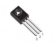
Only you know what is possible by looking at the components. Could a flatpack T0126 device (as shown below) be fitted possibly by drilling the heatsink ?
If the original TR11 is OK (and a suitable device) then there is no problem reusing it.
Did you check by measurement that all 12 of the 0.5 ohm emitter resistors were OK ?
Replacing the driver transistors will need some thought...
Attachments
As Jaycee say no
If the offset adjustment VR1 can swing the output above and below 0.00 volts then that is a good indication all is well.
Order the MJ's. Are the original insulating washers and bushes OK ?
TR11, originally a 2SC281. Electrically, replacing this is straightforward. The problem is that whatever is fitted must be in thermal contact with the heatsink in the same way the original is.
Only you know what is possible by looking at the components. Could a flatpack T0126 device (as shown below) be fitted possibly by drilling the heatsink ?
If the original TR11 is OK (and a suitable device) then there is no problem reusing it.
Did you check by measurement that all 12 of the 0.5 ohm emitter resistors were OK ?
Replacing the driver transistors will need some thought...
Fitting a flat one will not be a problem but I don't find anything avaiable with similar characterictics Transistors Bipolar - BJT | Mouser
I checked the resistors and they seem to work, but I will buy some substitutes anyway.
A review of what I'm going to order, any advice is welcome
- 6 MJ21194G
- 6 MJ21193G
- 4 1N4744A-TAP as substitutes for D11-D12 removed for testing
- 8 T93XB472KT20
- 6 T93XB471KT20
- 2 M64Y101KB40
- 2 RS02B1K300FB12 for the power supply board (I used 1.5K)
- 4 AC05000004708JAC00 R87-88 amp board
- 12 RS005R50466200FE73 R77-78-81-82-85-86 amp board
- 12 4662 mica insulators
- 2 294-820K-RC R1 amp board
I couldn't find:
- 330k trimmers, VR1-2 on the meter board
- a substitute for the 2SC281, one of the two hitachi was substituted in the past with an unkwnon one, who doesn't touch the heatsink correctly.
As I said before a flat one could be fitted easily and I prefer this solution, but I couldn't find either the 2SA1668 or the 2S4382
- Any tought on the 2SA810 Q7-8-19 on the amp board?
http://it.mouser.com/Search/ProductDetail.aspx?R=294-820K-RCvirtualkey21980000virtualkey294-820K-RC
I'll have a look later at the transistors.
Q11 could be something like an MJE340. Any generic NPN is absolutely fine for a vbe multiplier. MJE340 and an insulating kit sorted.
Drivers are going to be the problem. The old standby of MJE340 and MJE350 are just not really sufficiently rated current wise for supplying 3 pairs of outputs although they would work well and reliably for testing and getting the amp up and running. It would be at full power testing that they would be problematic.
470K is fine for the meter trimmers (do they need replacing ?)
Q11 could be something like an MJE340. Any generic NPN is absolutely fine for a vbe multiplier. MJE340 and an insulating kit
sorted. Drivers are going to be the problem. The old standby of MJE340 and MJE350 are just not really sufficiently rated current wise for supplying 3 pairs of outputs although they would work well and reliably for testing and getting the amp up and running. It would be at full power testing that they would be problematic.
470K is fine for the meter trimmers (do they need replacing ?)
470K is fine for the meter trimmers (do they need replacing ?)
Not really but since they are cheap enought I will order them as suggested
If the driver transistors 2SA483/2SC783 are dead, i'd recommend substituting MJE15032/3 or MJE15034/5. These are TO-220 devices, so you would have to remove the TO-66 mounting and socket to fit them. It wouldn't be too hard though.
I would however be concerned that substitution in both the driver and output transistors may mean that the compensation components in the circuit need modification to ensure overall stability. This is becoming less of a repair and more of a rebuild.
I would however be concerned that substitution in both the driver and output transistors may mean that the compensation components in the circuit need modification to ensure overall stability. This is becoming less of a repair and more of a rebuild.
If the driver transistors 2SA483/2SC783 are dead, i'd recommend substituting MJE15032/3 or MJE15034/5. These are TO-220 devices, so you would have to remove the TO-66 mounting and socket to fit them. It wouldn't be too hard though.
I would however be concerned that substitution in both the driver and output transistors may mean that the compensation components in the circuit need modification to ensure overall stability. This is becoming less of a repair and more of a rebuild.
The driver transistors are probably fine, at least on a basic test, plus they are all original with no visible damage.
If this substitution could be too problematic I could skip this part. I was interested in changing them just because I would like this amp to work for an other 40 years
- Status
- This old topic is closed. If you want to reopen this topic, contact a moderator using the "Report Post" button.
- Home
- Amplifiers
- Solid State
- Help repairing Pioneer M3