"if it aint broke, dont fix it". I'd leave the original drivers alone if they work.
Very true and good advice.
Perhaps using the originals might be best to get the amp working (assuming they are OK) and think about options later.
Its a tough one, I don't know what to advise you for the best on that.
I think we have to see how it all shapes up as it comes together.
Do we have a plan then ?
Just looking through your parts list in the earlier post. MJ transistors and washers are fine. However mica washers need thermal paste to work properly. The other alternative are the silicon pads which are used dry and are clean. I believe the "old fashioned" mica plus compound is the best for thermal transmission though.
Have you actually found any failed resistors ? just asking with you ordering some.
What are all the trimmers for") 8 x 4K7's
8 x 4K7's
Don't forget the MJE340's for the vbe multiplier. They are a T0126 package so you need insulating washers for those.
Just looking through your parts list in the earlier post. MJ transistors and washers are fine. However mica washers need thermal paste to work properly. The other alternative are the silicon pads which are used dry and are clean. I believe the "old fashioned" mica plus compound is the best for thermal transmission though.
Have you actually found any failed resistors ? just asking with you ordering some.
What are all the trimmers for
8 x 4K7'sDon't forget the MJE340's for the vbe multiplier. They are a T0126 package so you need insulating washers for those.
Do we have a plan then ?
Just looking through your parts list in the earlier post. MJ transistors and washers are fine. However mica washers need thermal paste to work properly. The other alternative are the silicon pads which are used dry and are clean. I believe the "old fashioned" mica plus compound is the best for thermal transmission though.
Have you actually found any failed resistors ? just asking with you ordering some.
What are all the trimmers for
Don't forget the MJE340's for the vbe multiplier. They are a T0126 package so you need insulating washers for those.
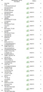
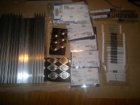
I order everything but I'm not sure I got the right isolators 1, 2, 3, 4
In any case I don't think it will be a problem I can find something locally if necessary.
I need to buy some thermal paste
Attachments
Last edited:
They all look OK. Quantities seem a bit high for some
As a repair project this all has to be done carefully and slowly checking everything along the way. I can understand you wanting to order as much as possible but that approach might be unrealistic in practice.
One component that should perhaps be replaced is VR2 which is the preset that adjusts the bias. If the preset was intermittent then the bias current would increase which is destructive. When ordering presets remember that the modern small mutiturn ones won't directly fit the PCB and that adding wires to parts is messy. Drilling the PCB is an option or try and get parts like the original style. If they have wires attached then they won't be held firmly enough to adjust. At the moment and for testing VR2 isn't a problem because we have it (the whole multiplier) shorted out.
Don't do anthing in haste
To be going on with you can fit one pair of output devices. Are we going for new insulating washers ? With thermal grease ?
Make sure the heatsink is clean and DO NOT overtighten the transistors. Tight, but not that tight it distorts anything.
If you are replacing the 0.5 ohm resistors then now is a good time.
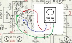
Familiarise yourself with the pin outs of the MJE340 (that we will use for Q11) although we keep that shorted still for the time being.
The diagram in post #112 shows the pins as 3,2,1 when looked at from above. 3 is the Emitter, 2 is the Collector and 1 is the Base.
I think it best to use the original driver transistors for now to avoid risks of connection errors. Lets get one channel working first.
To be going on with you can fit one pair of output devices. Are we going for new insulating washers ? With thermal grease ?
Make sure the heatsink is clean and DO NOT overtighten the transistors. Tight, but not that tight it distorts anything.
If you are replacing the 0.5 ohm resistors then now is a good time.
Familiarise yourself with the pin outs of the MJE340 (that we will use for Q11) although we keep that shorted still for the time being.
The diagram in post #112 shows the pins as 3,2,1 when looked at from above. 3 is the Emitter, 2 is the Collector and 1 is the Base.
I think it best to use the original driver transistors for now to avoid risks of connection errors. Lets get one channel working first.
Don't do anthing in haste
To be going on with you can fit one pair of output devices. Are we going for new insulating washers ? With thermal grease ?
Make sure the heatsink is clean and DO NOT overtighten the transistors. Tight, but not that tight it distorts anything.
If you are replacing the 0.5 ohm resistors then now is a good time.
Familiarise yourself with the pin outs of the MJE340 (that we will use for Q11) although we keep that shorted still for the time being.
The diagram in post #112 shows the pins as 3,2,1 when looked at from above. 3 is the Emitter, 2 is the Collector and 1 is the Base.
I think it best to use the original driver transistors for now to avoid risks of connection errors. Lets get one channel working first.
New resistors...
New output transistors...
32mv at L1 after testing, what's the next step?
That actually sounds like the channel is OK.
If you had an oscilloscope I would say put a 1KHz sine wave signal into the amp and check it on the scope. You could try with an old speaker and see if you get reasonable sound out at low volume - you'll have some distortion because there's no bias current, but it'd prove the circuit was working OK.
If you had an oscilloscope I would say put a 1KHz sine wave signal into the amp and check it on the scope. You could try with an old speaker and see if you get reasonable sound out at low volume - you'll have some distortion because there's no bias current, but it'd prove the circuit was working OK.
That actually sounds like the channel is OK.
If you had an oscilloscope I would say put a 1KHz sine wave signal into the amp and check it on the scope. You could try with an old speaker and see if you get reasonable sound out at low volume - you'll have some distortion because there's no bias current, but it'd prove the circuit was working OK.
Ok... I don't have an oscilloscope, but if I want to get serious about this hobby I need to buy one. Any suggestion for something below €100?
EDIT: probably €100 it's too low, let's say the one who will work right for the least possible amount
Last edited:
Scopes... search the forum... there are many threads on choosing and using scopes. My opinion is still unchanged, get an analogue type (that means with a CRT display) that has at least 20Mhz bandwidth. Higher bandwidth is better but 20Mhz will cover all this type of work in practice.
Moving on
It does sound good up to now. By carefully monitoring the "L1" voltage you should be able to trim that to 0.00 by means of VR1.
Next step has to be reinstating the Vbe multiplier Q11. Using an MJE340 this device must be fitted to the heatsink in the same sort of physical area that the original was mounted. The transistor has to accurately sense the temperature of the heatsink. If you have to drill the heatsink then make sure there are no burrs on the metal. The tiniest metal "flakes and chips" can puncture any insulating washer. When the transistor is mounted then check using a high ohms range on your meter that there is no electrical contact between the heatsink and the transistor leads.
Before wiring the transistor to the pcb you must turn VR2 so that it is at minimum resistance. You can check by measuring (on ohms range) across R33 that is across the preset. You want it turned to the end that gives the lowest resistance. It should ideally be zero ohms but pre-sets often have a few ohms of resistance even at minimum.
Wire the transistor to the PCB making 100% sure the connections are correct as shown.
Remove the short we applied earlier across the transistor.
Still keeping just the one pair of outputs fitted the amp can now be powered up again. Assuming all looks OK the voltage on L1 is checked again (and should still be around zero).
Now we try adjusting VR2.
Look at the circuit. The pin TP9 allows you to monitor the voltage across the 0.5 ohm resistors. You connect your meter (on a low DC voltage range between pins 9 and the output Pin 13.
This voltage should be near zero to begin with. If you now carefully and slowly turn VR2 the voltage between pins 9 and 13 should start to rise. As the voltage rises the bulb will start to glow (that's correct). A voltage of 0.050 (50 millivolts) means 100ma is flowing in the outputs but before you try and reach that, read below.
That's a good enough test for now that all is well. As the bulb brightens the supplies in the amp are falling so don't turn it up much because the amp may do something unpredictable with the low supplies. Just confirm that you can start to brighten the bulb and then return the setting back to zero.
Attachments
Scopes... search the forum... there are many threads on choosing and using scopes. My opinion is still unchanged, get an analogue type (that means with a CRT display) that has at least 20Mhz bandwidth. Higher bandwidth is better but 20Mhz will cover all this type of work in practice.
Moving on
It does sound good up to now. By carefully monitoring the "L1" voltage you should be able to trim that to 0.00 by means of VR1.
Next step has to be reinstating the Vbe multiplier Q11. Using an MJE340 this device must be fitted to the heatsink in the same sort of physical area that the original was mounted. The transistor has to accurately sense the temperature of the heatsink. If you have to drill the heatsink then make sure there are no burrs on the metal. The tiniest metal "flakes and chips" can puncture any insulating washer. When the transistor is mounted then check using a high ohms range on your meter that there is no electrical contact between the heatsink and the transistor leads.
Before wiring the transistor to the pcb you must turn VR2 so that it is at minimum resistance. You can check by measuring (on ohms range) across R33 that is across the preset. You want it turned to the end that gives the lowest resistance. It should ideally be zero ohms but pre-sets often have a few ohms of resistance even at minimum.
Wire the transistor to the PCB making 100% sure the connections are correct as shown.
Remove the short we applied earlier across the transistor.
Still keeping just the one pair of outputs fitted the amp can now be powered up again. Assuming all looks OK the voltage on L1 is checked again (and should still be around zero).
Now we try adjusting VR2.
Look at the circuit. The pin TP9 allows you to monitor the voltage across the 0.5 ohm resistors. You connect your meter (on a low DC voltage range between pins 9 and the output Pin 13.
This voltage should be near zero to begin with. If you now carefully and slowly turn VR2 the voltage between pins 9 and 13 should start to rise. As the voltage rises the bulb will start to glow (that's correct). A voltage of 0.050 (50 millivolts) means 100ma is flowing in the outputs but before you try and reach that, read below.
That's a good enough test for now that all is well. As the bulb brightens the supplies in the amp are falling so don't turn it up much because the amp may do something unpredictable with the low supplies. Just confirm that you can start to brighten the bulb and then return the setting back to zero.
I installed Q11... no problem
I changed VR1 and now L1 is 0 (it goes from positive to negative and viceversa)
I substitute VR2 and set it at the lowest possible amuont (3ohm in my case)
When I check pin 9 and 13 the output is negative -19mv (VR2 3ohm), if I increase VR2 it goes to -22mv... no matter what I do ith VR2 it's always negative

Are Q24 & Q27 the only o/p transistors installed?
What is the DCV at Q11-Coll & D6-Cathode with respect to ground? When you adjust the bias pot, VR2(470) the voltage across these nodes should increase up to what is printed in the schematic +/- 1.9V [3.6V] (~ 3 Vbe drops x2) Anything more = trouble.
Rick
What is the DCV at Q11-Coll & D6-Cathode with respect to ground? When you adjust the bias pot, VR2(470) the voltage across these nodes should increase up to what is printed in the schematic +/- 1.9V [3.6V] (~ 3 Vbe drops x2) Anything more = trouble.
Rick
Last edited:
Are Q24 & Q27 the only o/p transistors installed?
What is the DCV at Q11-Coll & D6-Cathode with respect to ground? When you adjust the bias pot, VR2(470) the voltage across these nodes should increase up to what is printed in the schematic +/- 1.9V [3.6V] (~ 3 Vbe drops x2) Anything more = trouble.
Rick
Only two o/p transistrors in and D11-12 not installed, everything else as in the diagram.
dcv at Q11 collector is 1.910V (VR2 low as possible) at D6 -1.905V, voltage between pin 9 and 13 is -21mv, voltage at L1 almost 0
Last edited:
I installed Q11... no problem
I changed VR1 and now L1 is 0 (it goes from positive to negative and viceversa)
I substitute VR2 and set it at the lowest possible amuont (3ohm in my case)
When I check pin 9 and 13 the output is negative -19mv (VR2 3ohm), if I increase VR2 it goes to -22mv... no matter what I do ith VR2 it's always negative
That's seems fine... so far
The voltage across the test points will always be of one polarity. Pin 9 will always be positive with respect to pin 13.
All seems well so far...
So what's the next step ? It all depends on how easy or otherwise this is to work on.
You need to refit the diodes D11 and D12 that we lifted earlier. That should have no effect on the results so far but as always, reconfirm all is well after refitting them.
So next step is probably fitting the remaining two pairs of outputs and again reconfirming the above adjustments still work OK
L1 3mv, pin 9-13 -12mv... I suppose is time to test it with a real speaker
You can do providing you are sure all is connected correctly.
Did we short the input resistor (R1 820K) out. Be absolutely certain that the PCB is connected correctly.
Use the bulb tester and don't turn it up loud because that could cause an unpredictable latch up with disastrous consequences (due to rails being severely current limited due to the bulb)
Test carefully
or dummy load R (8ohm) and put the DMM across the load R measuring ACV and watch the meter jump to the music. Would not want it more than say 10V peak output (~12W) unless you have a hi-power load R (100-200W)I suppose is time to test it with a real speaker
Once you have passed the dim bulb test that is and all the components are back in place.
Last edited:
Good news,as you can hear one channel is working right as expected
Video - TinyPic - Free Image Hosting, Photo Sharing & Video Hosting
Bad news...
I started working on the second channel following the same steps:
- I removed D11, D12 and R1
- I connected Q11 to D6
- I changed all 0.5ohm resistors and VR1 VR2
- I set VR1 and VR2 as low as possible
- new o/p transistors in
Test it, something wrong, bulb ligh on... then I changed Q11, try it again but nothing. I carefully checked the board for any sign of short or any visible damage, but I can't find anything
- Status
- This old topic is closed. If you want to reopen this topic, contact a moderator using the "Report Post" button.
- Home
- Amplifiers
- Solid State
- Help repairing Pioneer M3