A lot of posts since last night...
We are not measuring current anywhere yet as this stage")
R26 is an odd one. Looking at the circuit in detail its simply a resistive divider in conjunction with R14 and relies on the current drawn off that rail to keep the voltage on R26 from going to high. The transistor is just a ripple filter.
In simple terms that means R26 will smoke until all the amp is connected up.
If you need to work on the power board then isolate R14 (1K5) and replace R26 when finished.
So pin 4 we know about now and how to make the board safe to work on.
Lets look at pin 12 first...
I think this is the same kind of issue. The supply is unloaded and so the voltage will rise to the value of the rail feeding it which is essentially the 57 volt stabilised rail. So no problem there.
Pin 14. Again an unloaded and resistively fed supply so no problems.
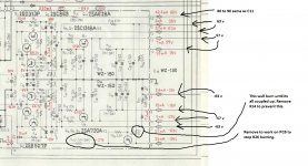
The test didn't go smooth as expected, some smoke come out from a restistor and the values I measured are not as they should be (check the picture)
Also when I tried to measure mA at 1 - 3 the bulb turn on
We are not measuring current anywhere yet as this stage
The resistor is R26 10k
The voltage at C11 and C12 is 90V
I checked the connection on 15 and 9, now voltage at 14 is 90V, at 8 0.8V and at 4 77V. All the other voltage didn't vary
R26 is an odd one. Looking at the circuit in detail its simply a resistive divider in conjunction with R14 and relies on the current drawn off that rail to keep the voltage on R26 from going to high. The transistor is just a ripple filter.
In simple terms that means R26 will smoke until all the amp is connected up.
If you need to work on the power board then isolate R14 (1K5) and replace R26 when finished.
Voltages at different pins
5 - 63 (should be 63)
6 - 13 (13)
7 - 57 (57)
8 - 0.8 (15)
10 - 16 (15)
11 - 58 (57)
12 - 59 (35)
13 - 64 (63)
14 - 90 (60)
so everything fine except 8, 12 and 14
I forgot pin 4, yes it's still high 77V instead of 24.
I will unmount the board and check the resistors, for replacement can I use 2W kiwame?
So pin 4 we know about now and how to make the board safe to work on.
Lets look at pin 12 first...
I think this is the same kind of issue. The supply is unloaded and so the voltage will rise to the value of the rail feeding it which is essentially the 57 volt stabilised rail. So no problem there.
Pin 14. Again an unloaded and resistively fed supply so no problems.
Just to be sure I understand everything I try to do a sum up of what I need to do
- Pin 8 substitute R22 1.3K and check for an open circuit
- Pin 4 substitute R26 10K and disconnect R14 as long as I work only on the PB
Then I will test again, if the problem on pin 8 is solved I will assemble back the amp except for the two output boards and check the voltage after the big caps
- Pin 8 substitute R22 1.3K and check for an open circuit
- Pin 4 substitute R26 10K and disconnect R14 as long as I work only on the PB
Then I will test again, if the problem on pin 8 is solved I will assemble back the amp except for the two output boards and check the voltage after the big caps
I don't agree with you there Mooly, I am pretty sure D13, D14 and D15 are actually Zener diodes, so pin 10 will be 15V, pin 8 -15V, and pin 6 -13v with respect to terminal 9.
edit: yes, WZ-150 is a 15v 500mW zener diode, and WZ-130 is a 13v 500mW zener diode - so those rails are shunt regulated.
edit: yes, WZ-150 is a 15v 500mW zener diode, and WZ-130 is a 13v 500mW zener diode - so those rails are shunt regulated.
That should be fine although they are marked as 2K on my diagram. The only reservation I have is that without those rails supplying the amp, then the current in the zener will be higher than normal. It will be (57-15)/R which might be on the high side for long term.
I would measure those -/+ 15v rails first and quickly and then switch off. If you want to work further on the PSU then remove R21 and R22.
I would measure those -/+ 15v rails first and quickly and then switch off. If you want to work further on the PSU then remove R21 and R22.
Pin 4 is correct with R14 disconnected.
Pin 5 is correct at minus 64 v
Pin 6 is correct at minus 13 v
Pin 7 is correct at minus 57 v
Pin 8 is incorrect. If the resistor R22 is OK then the zener D14 is 99% faulty (the 1% is if the caps across it were short/leaky). This needs replacing with a 15 volt 1.3 watt type such as BZX61C15V0
Pin 10 is correct at +15 v
Pin 11 is correct at +58 v
Pin 12 is correct at +59 v (There is a resistive divider on the output which is why it is lower than pin 13)
Pin 13 is correct at + 64v
Pin 14 is correct at + 89v
it say 2k on the diagram and 1.3k on the board picture.
I removed a 1.3k from the actual board so I belive the pictures are more accurate than the diagram
Not 100% conclusive but measure R21 which is shown as the same value (and probably is) as these feed a symmetrical -/+ 15 v supply.
Not 100% conclusive but measure R21 which is shown as the same value (and probably is) as these feed a symmetrical -/+ 15 v supply.
It's 1.3k... should I substitute it with a 1.5k so it's the same as R22?
for the diode if I understanded right I need to buy something like this Buy Zener Diodes 15V Zener diode,BZX85C15 1.3W Magnatec BZX85C15V online from RS for next day delivery.
The cap is new so I doubt it could be the problem
If R21 is 1.3K (you are measuring these out of circuit or reading the value on the actual part.... just to be clear ) then its 1.3K for a reason. For getting the amp up and running though, 1K5 should be fine. We can easily check later whether or not they need to be higher or lower.
Those diodes are fine and you should be able to get those (or similar) anywhere.
) then its 1.3K for a reason. For getting the amp up and running though, 1K5 should be fine. We can easily check later whether or not they need to be higher or lower.Those diodes are fine and you should be able to get those (or similar) anywhere.
If R21 is 1.3K (you are measuring these out of circuit or reading the value on the actual part.... just to be clear
Those diodes are fine and you should be able to get those (or similar) anywhere.
I just read it, I don't want to remove it if not necessary since it will easily broke (the other 1.3k I removed was stuck in the pcb and I had to cut it in for not damaging the board)
The diode wattage worst case is,
[(57-15)/1300]*15 which is around 0.5 watt (approx.) so a 1.3 watt part is ideal.
The manual shows 26 millamps drawn from the +15v line which leaves 6 milliamps for the zener. That's OK.
For the - 15 volt line its shown as 15 milliamps drawn so that means more current flows in the zener if we kept to the same resistor values.
If the resistor is to high in value then the zener is starved of current and regulation is poor. Go to low and power is wasted in the resistor (it gets hot) and the so to the zener.
So it looks like a zener will fix the PSU and then you are ready to move on to the main event
pin 8... -15
Now I need to test the big caps but I have a couple of questions, firslty should I reconnect R14? Secondly is it better to test the caps alone and then connect the other boards to the power supply or I can attach everything now and proceed with testing
- Status
- This old topic is closed. If you want to reopen this topic, contact a moderator using the "Report Post" button.
- Home
- Amplifiers
- Solid State
- Help repairing Pioneer M3