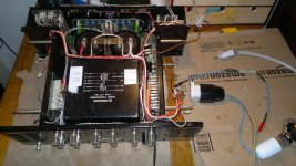
Could this be a good solution for fixing the transformer foots?
An externally hosted image should be here but it was not working when we last tested it.
Update
So far...
- I changed all small caps with exact value (somethimes with higher voltage rating) 6 elna and the rest from nichicon
- I cleaned all the boards, connections, switches, potentiometer
- I recabled the transformer but I'm still waiting for the resin. I checked the transformer voltage and temperature after 30 minutes with no load, everything fine
My next test will be to check voltage after the power supply board and then after the big caps. Any help on what to do next?
Attachments
Last edited:
None of the original transistors is left, they were changed in the past. I'm also quite sure that some (or all) actual transistors are damaged.
One of the two amp modules seems in better condition, I can start from that and try both transistors boards, maybe one of them will work
One of the two amp modules seems in better condition, I can start from that and try both transistors boards, maybe one of them will work
You must power it all via the bulb tester when connecting and testing the PSU.
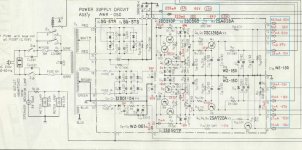
So connect the tranny to the PSU board and confirm all the voltages marked in red at the right hand side of the board. The -/+66 volts and -/+60 volt rails may be a little high off load but all the others should be as marked.
When you switch off make sure all the rails are discharged before working on anything. The -/+ 57 volt rails haven't got a resistive path to ground and so will stay charged. Use a 10K or similar to discharge them.
You must power it all via the bulb tester when connecting and testing the PSU.
So connect the tranny to the PSU board and confirm all the voltages marked in red at the right hand side of the board. The -/+66 volts and -/+60 volt rails may be a little high off load but all the others should be as marked.
When you switch off make sure all the rails are discharged before working on anything. The -/+ 57 volt rails haven't got a resistive path to ground and so will stay charged. Use a 10K or similar to discharge them.
The bulb tester is in and I have a 100r 10w for the discharge
")
But just to be sure before proceding... I will only connect the tranny to the pb and nothing else, then I will connect the multimeter on the 9 and check the red value showed in the diagram
Attachments
You cannot measure current draw by simply putting the meter over terminals the way you do with voltage. If you try to do that, you are actually putting the voltage through a very small resistance in the meter, which is practically a short circuit. To measure current, you must insert the meter's leads in series with the circuit drawing the load.
Your bulb has just saved you from shorting out those huge capacitors with your multimeter - probably creating a loud bang and lots of smoke in the process
Your bulb has just saved you from shorting out those huge capacitors with your multimeter - probably creating a loud bang and lots of smoke in the process
You cannot measure current draw by simply putting the meter over terminals the way you do with voltage. If you try to do that, you are actually putting the voltage through a very small resistance in the meter, which is practically a short circuit. To measure current, you must insert the meter's leads in series with the circuit drawing the load.
Your bulb has just saved you from shorting out those huge capacitors with your multimeter - probably creating a loud bang and lots of smoke in the process
no bang or smoke, the bulb just turn on and I immeditely turn off everything... btw the big capacitators are not connected yet, at the moment I only connected the power supply board to the tranny
What about the other measures? especially the 120v instead of 60v
The big capacitors not being connected will explain your 46V on terminal 1 - the meter is probably being confused because the raw rectified voltage is not being smoothed.
As for the other readings, I would make sure there is a good solid connection between terminal 15, the brown wire of the transformer, and terminal 9. any resistance there could cause floating voltages.
Measure the voltages on C11 and C12, where it says 83v and -83v.
Which resistor smoked?
As for the other readings, I would make sure there is a good solid connection between terminal 15, the brown wire of the transformer, and terminal 9. any resistance there could cause floating voltages.
Measure the voltages on C11 and C12, where it says 83v and -83v.
Which resistor smoked?
The big capacitors not being connected will explain your 46V on terminal 1 - the meter is probably being confused because the raw rectified voltage is not being smoothed.
As for the other readings, I would make sure there is a good solid connection between terminal 15, the brown wire of the transformer, and terminal 9. any resistance there could cause floating voltages.
Measure the voltages on C11 and C12, where it says 83v and -83v.
Which resistor smoked?
The resistor is R26 10k
The voltage at C11 and C12 is 90V
I checked the connection on 15 and 9, now voltage at 14 is 90V, at 8 0.8V and at 4 77V. All the other voltage didn't vary
Just to check, is this part of the power supply connected to anything else in the amp ?
Voltage on C11/C12 is a little high, but probably normal if your mains voltage is slightly higher than usual. I wouldn't be concerned there.
The voltage on terminal 4 suggests Q9 is shorted, possibly why R26 smoked. Low voltage on pin 8 suggests R22 is open circuit or Q8 failed. What voltage do you get on terminal 7 ?
Did you notice this power transformer has an extra primary winding ? You can connect them in series and use the amp on 230 V with more or less the indicated values that are in the schematic. I don't know where you live but we have 230 V (and over) for ages now.
You should connect the lower blue to the upper grey wire as indicated on the transformer itself. The other blue and grey wire are the connections for 230 V then.
Beware ! The blue windings are drawn as primary windings but they could be secondary windings used for other purposes. Please check the schematics for what's connected to them in reality.
Last edited:
Just to check, is this part of the power supply connected to anything else in the amp ?
Voltage on C11/C12 is a little high, but probably normal if your mains voltage is slightly higher than usual. I wouldn't be concerned there.
The voltage on terminal 4 suggests Q9 is shorted, possibly why R26 smoked. Low voltage on pin 8 suggests R22 is open circuit or Q8 failed. What voltage do you get on terminal 7 ?
57V on terminal 7
Only 9, 15 and the secondaries connected to the power board
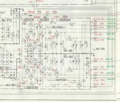
pin 8, look at R22 - my guess is it's open circuit or high resistance.
Pin 14, is not regulated so the higher voltage is likely because there is no load.
Pin 12 seems to be set by a resistor divider made by R23 and R25. Check these resistors are the right value, particularly R25.
You left out pin 4, if it is still high, check Q9 isn't shorted C-E and replace R26.
Pin 14, is not regulated so the higher voltage is likely because there is no load.
Pin 12 seems to be set by a resistor divider made by R23 and R25. Check these resistors are the right value, particularly R25.
You left out pin 4, if it is still high, check Q9 isn't shorted C-E and replace R26.
- Status
- This old topic is closed. If you want to reopen this topic, contact a moderator using the "Report Post" button.
- Home
- Amplifiers
- Solid State
- Help repairing Pioneer M3