OK guys, this is getting silly. So let's get back to basics.
1. There are two grounds.
- Ground 1 is the source's ground which comes to the amplifier through the RCA input wire ground termimal.
- Ground 2 is the amplifier ground.
2. Ground 1 should only be used by the input network and feedback networks, i.e. return point for R1, R3, C2 (input network) and C3, C4 (feedback network). Nothing else should be returned to this ground.
3. Ground 2 should be used for everything else, including:
- Loudspeaker return line
- Rail decoupling caps C12, C13, C16, C17
- Any other grounds.
4. Ground 1 and Ground 2 should be decoupled with a ground decoupling circuit consisting of a small resistor (5-10 ohms) and back to back to back diodes to avoid Ground Loops. In the HB these are R4 (5 ohms) and D1, D2.
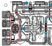
I checked today the PCB for the HB. I used the one on the build guide.
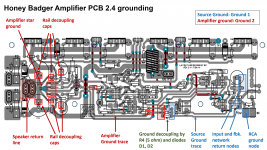
The PCB follows the guidelines I describe above. You can see it in the attached image.
- Red text refers to the amplifier ground
- Blue text referes to the source ground
- Boxes are where a component connects to the ground
So PCB is correct, schematic is wrong, such is life... fix the schematic.
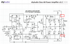
To fix it, the ground labels should be as shown in the attached schematic.
Best, Sandro
Attachments
Last edited:
Maybe its best if we do update the schematic to call it V2.41 so people don't get it confused with the current PCB version 2.4
41? Huh!? How about 17 or 823?

I vaguely recall that 4+1=5 and I am pretty sure that 4+1=41 is wrong.
If you want to change the version number, my vote is for 2.5, not 2.41 or 2.17 or 2.823.
Also, if you decide to change the "GND labels", don't just use "G1" or "G2", because these are pretty meaningless (or even misleading). As I wrote before, the best option would be to use no label(s) at all. If this does not make you happy, "Amplifier GND" and "Source GND" might be a good compromise.
As I wrote before, the best option would be to use no label(s) at all. If this does not make you happy, "Amplifier GND" and "Source GND" might be a good compromise.
No labels ... terrible idea.
"Amplifier GND" and "Source GND"... good idea.
Look at post #4022. I highlighted in the schematic in red, the labels that are wrong in the schematic.Looks like the schematic agrees with the layout.
BTW, I am not suggesting that we should stick to G1 & G2 nomenclature, only pointing out what is wrong and a potential fix.
How about just delete the labels... better to not be there, than being misleading and wrong.
Exactly my point. But you didn't like it:
No labels ... terrible idea.
Whatever you do, make sure the Honey Badger documentation stays as good as it is. It's a great amp and a great project!
I have to say that most of the guys on the forum are clearly very experienced and specialise in one thing or another.
But what about the first time builder?
The Honey Badger seams to be a very popular first or second amplifier to build on this site.
Can you guys honestly say that all the documention, bill of materials and build guide is perfect and cannot be improved in anyway.
I think what Sandro is try to do is make things clearer for the first time builder.
For the experienced builder I'm sure you can work with just about anything even if its not 100% clear.
I for one would like to see the image that Sandro kindly created added to the build guide documentation.
Documentation like the G1, G2 thing leaves new builders chasing their tails when it comes time to troubleshoot. It's not relevant, the ground scheme is built into the board. It's pretty tough to change and is a bad idea to do, so why fixate on it? Using it as a teaching aid is a different story, but in that case an LTSpice schematic isn't great anyways.
I will say reversing Pete's numbering scheme on the schematic is offensive to me. In all of his schematics that I've worked with (which are many) G1 is the main supply ground. He's the artist. That's his markings. If someone's documentation doesn't match, change it, not the artwork.
As for BOMs, they're a tough go. With through hole parts they are usually obsolete the day after they are released. Parts are superseded daily. Worse yet parts are sometimes flat out changed without any revision to the part number. The world has switched to SMT and supplies of them are much more stable. The only problem with them is the ridiculous notion that they are harder to work with.
Has anyone used a Sanken driver/output combo like these:
2SA1668/2SC4382
2SA2151A/2SC6011A
They are in stock at DigiKey and I found a post from OStripper that mentioned them for a 4R load with lower rails:
post #1994
2SA1668/2SC4382
2SA2151A/2SC6011A
They are in stock at DigiKey and I found a post from OStripper that mentioned them for a 4R load with lower rails:
post #1994
Last edited:
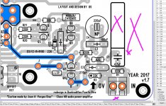
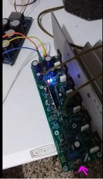
is my fault I shouldn't add that RCA option there
ST I saw that you cut the traces did that fix the problem? I need to jump in because I think is my fault "it is indeed" that this idea of the RCA is causing problem to Stuart I can put it together and tested again but I remember that it was no sounds of hiss or hum noises, and I guess my idea of putting an RCA was a "optional" and I didn't know that this will cause like a antenna effect and having those copper areas top and bottom made that anomaly sounds hiss distortions like a capacitor effect
ST I saw that you cut the traces did that fix the problem? I need to jump in because I think is my fault "it is indeed" that this idea of the RCA is causing problem to Stuart I can put it together and tested again but I remember that it was no sounds of hiss or hum noises, and I guess my idea of putting an RCA was a "optional" and I didn't know that this will cause like a antenna effect and having those copper areas top and bottom made that anomaly sounds hiss distortions like a capacitor effect
Attachments
Last edited:
Exactly my point. But you didn't like it:
I know... I am compromising... better not there than wrong. As a compromise, a paragraph in the build guide would also be good.
BTW, found another discrepancy between the PCB and the schematic in the website, which I just realized it is v2.2 and not v2.4
The schematic I am referring to is here:
https://cdn.shopify.com/s/files/1/1006/5046/files/P-DIYAB-2V20-diyAB-amp-schematic.pdf
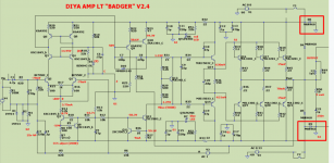
Diodes D8 and D9 are not present... see screenshots.
- PCB has them
- The white background schematic on the store website (2.2) does not have them
- The green background schematic has them (2.4).
Now, if the come back argument is going to be "You are looking at the wrong version of the schematic", shouldn't the right version be the one on the store front website?
Also, it is the same schematic as the one that is on page 2 of the build guide... with the same omissions.
Here is an interesting question:
Who owns the copyrights to the HB nowadays? Pete?
I.e. who is the right recipient of feedback for changes to the schematic or build guide.
The schematic I am referring to is here:
https://cdn.shopify.com/s/files/1/1006/5046/files/P-DIYAB-2V20-diyAB-amp-schematic.pdf
Diodes D8 and D9 are not present... see screenshots.
- PCB has them
- The white background schematic on the store website (2.2) does not have them
- The green background schematic has them (2.4).
Now, if the come back argument is going to be "You are looking at the wrong version of the schematic", shouldn't the right version be the one on the store front website?
Also, it is the same schematic as the one that is on page 2 of the build guide... with the same omissions.
Here is an interesting question:
Who owns the copyrights to the HB nowadays? Pete?
I.e. who is the right recipient of feedback for changes to the schematic or build guide.
Attachments
Last edited:
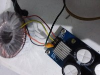
I'm back yes Stuart I do have that noise too but when I plugin the power plug I forgot to connect the GND wire to PSU and after I did that all noises were gone and I can not hear any sounds silent as a crypt
Attachments
Last edited:
What would happen then? Does this really prevent the amplifier from being damaged? Would the amp be damaged at all if one rail fails? Or is it rather the speaker that would let out that magic smoke?This is an educated guess:
They clamp the supplies to ground (within a diode drop) if the connection from the power supply to amplifier breaks. So essentially they are safety devices.
Best regards!
- Home
- Amplifiers
- Solid State
- diyAB Amp The "Honey Badger" build thread