Exactly what I found. I searched for any film cap 270pf and came up with nothing. Mouser has a couple but I was trying to buy everything from one supplier. I tried Mouser first and it was a couple of items right off the bat they did not have and so far Digikey has had everything except these 270pf caps but not in polystyrene. Pico farad's are so little I do not see how being some off is going to effect an audio circuit. It is coming off of the input and going to ground through a resistor so I do not think having a few pf's one way are the other is going to have that big of an effect. Could be wrong and if so maybe someone can explain how and then I will make orders from 2 suppliers and pay double shipping. As you can tell I am a cheap diy'er.
@Harry3: Do you know what is the difference between Polypropylene (PP) and Polypropylene (PP), Metallized?
Thanks!
If I am not mistaken metalized polypropylene is where the metal is bonded to the poly. I doubt that there are any, or at least very few, that are not metallized. Older caps had the metal sandwiched between the dielectric. Boutique caps, PIO, are still made that way.
Last edited:
A very quick search pulled up 16 choices in stock with min. qty. of 1 at digi-key for 220pF, so you shouldn’t have a problem picking one that will fit.
Thanks, certainly an option. I have already ordered the polystyrlene 430pf ones on Ebay. Two in series will give 215pf. I am guessing good enough for Gov work, at least I hope so.
A very quick search pulled up 16 choices in stock with min. qty. of 1 at digi-key for 220pF, so you shouldn’t have a problem picking one that will fit.
Thanks, certainly an option. I did some more searching on Digikey and they do have some polypropylene 560pf for .50C each. Two in series gives 280pf. Big but could be made to work.
Yep silver mica caps are good in that position as well.
As Sandro says 220pF is fine.
More info on film caps here:
Film capacitor - Wikipedia
Personally I would not put two caps in series in that position as they MIGHT act as an antenna, if the're physically long.
A small (sized) cap in that position is much preferred.

As Sandro says 220pF is fine.
More info on film caps here:
Film capacitor - Wikipedia
Personally I would not put two caps in series in that position as they MIGHT act as an antenna, if the're physically long.
A small (sized) cap in that position is much preferred.
Yep silver mica caps are good in that position as well.
As Sandro says 220pF is fine.
More info on film caps here:
Film capacitor - Wikipedia
Personally I would not put two caps in series in that position as they MIGHT act as an antenna, if the're physically long.
A small (sized) cap in that position is much preferred.
Good point.
Personally I would not put two caps in series in that position as they MIGHT act as an antenna, if the're physically long.
Ultra good point!
Toriod 45V or 40V. Opinions?
voltage alone does not paint a full picture....
a 40v 800va is of course better than a 45v 200va in my book...so context here is very important..
Yep silver mica caps are good in that position as well.
As Sandro says 220pF is fine.
More info on film caps here:
Film capacitor - Wikipedia
Personally I would not put two caps in series in that position as they MIGHT act as an antenna, if the're physically long.
A small (sized) cap in that position is much preferred.
yes to silvered mica caps...they are not really hard to source..Silver mica capacitor - Wikipedia
caps in series? yes by all means if you have to....even if they maybe located some distance, twisting of wires is a good way to eliminate rfi....
but honestly, i have never done series caps that are a distance apart....
Hi Guy's
While chatting to Harry off line he noticed that there was a discrepancy between the location of the G2 (signal ground) and G1 (power ground) on the schematic
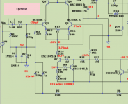
Can somebody confirm that my updated image is how the schematic should actually be labeled.
Thanks Harry, Great pickup
While chatting to Harry off line he noticed that there was a discrepancy between the location of the G2 (signal ground) and G1 (power ground) on the schematic
Can somebody confirm that my updated image is how the schematic should actually be labeled.
Thanks Harry, Great pickup
Attachments
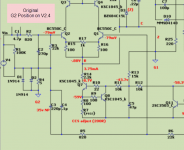
D1, D2 and R4 make up a ground lift/ loop breaker for the input. The ground symbol is the supply ground, the other side is the input/ signal ground or G2
The Ground Symbol shown in the original is showing the location of G2 which is what I am questioning.
It appears that its could be in the wrong location.
Attachments
Where G2 is marked is the audio ground.
Please add some more details.
Are you saying that where G2 is marked on the original schematic is the signal (Audio) ground?
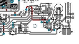
Because if you are it can't be. Just look at the traces on the PCB, Signal (Audio) ground is located between the junction of R4 and C2. Not on the other side of R4
Attachments
In the last schematic you posted, where G2 is marked at the junction of R4 and C2 is the correct location for audio ground.
D1, D2 and R4 are there to provide a little isolation between audio ground and the power supply ground. R4 would minimize the possibility of ground loops through your interconnects. D1 and D2 are to ensure the ground ring on the RCA connector can't have much more than .6V present for safety.
D1, D2 and R4 are there to provide a little isolation between audio ground and the power supply ground. R4 would minimize the possibility of ground loops through your interconnects. D1 and D2 are to ensure the ground ring on the RCA connector can't have much more than .6V present for safety.
- Home
- Amplifiers
- Solid State
- diyAB Amp The "Honey Badger" build thread