The Vivid speakers are Designed by Lawrence Dickey, that also was the man behind the B&W Nautilus speakers. I do have great respect for his designs.
He has, as one of the only in the industry, been working a whole lot with what goes on behind the membranes...He has by a smart magnet-motor design reduced rear-wave reflections from the driver hard structures. He has also been working quite a lot with transmission-line loading of tweeters and mid-ranges.
He relies solely on the use of anodized aluminum cones, and to me that is the greatest compromise in his designs. as they will have resonance peaks just about an octave away from their linear region. And to me there are other and better materials that could be used with better results...Or so I believe there is....Lawrence may think other vise...")
Have you ever heard the B&W nautilus speaker...?
all of the circuit details
Wouldn't it be fun if the two dozen ''69 MHz'' output devices turned out to be MJE15034/35 OnSemi duos ?

http://www.diyaudio.com/forums/solid-state/122501-driver-transistors-2sc5200-1943-a.html#post1502185
Some may wonder, why the 91% faster copper routine for an Eco bias switcher
(i have, several times, last occasion was less than a year ago, but the chief beatch says i can't have 'm, still looking for a contract hit person)
Wayne
No ... well yes I have heard the Nautilus, but not sufficient to have any opinion on the sound...
My admiration for Laurence dickey's work's is merely from the concepts and path's he follows....they are in concept quite similar to my beliefs. though my execution is quite different...
No ... well yes I have heard the Nautilus, but not sufficient to have any opinion on the sound...
My admiration for Laurence dickey's work's is merely from the concepts and path's he follows....they are in concept quite similar to my beliefs. though my execution is quite different...
Wouldn't it be fun if the two dozen ''69 MHz'' output devices turned out to be MJE15034/35 OnSemi duos ?
Wasn't it Elecrocompaniet that used drivers like that?
I doubt that DD is using 2x 12 low current driver devices because the design spec is 1200W into 2 ohms which would be outside the soar - even with that many devices in parallel. He is definitely not using OnSemi thermaltrak, because in his words - "it would not allow the control over bias that the design required."
Last edited:
Just curious, to see if you actually heard them (nautilus) i don't recall them being special for B&W ...
The problem with those speakers relates to the set up. There are no internal passive crossovers and B&W supplies a special active crossover / preamp to drive the required 2x 4 power amplifiers. I've witnessed some guys at a local hi-fi store get themselves deep into trouble - using a mix of power amps that had different voltage gains and with some inverting the signal. You really need to use 4 identical stereo amplifiers, or be completely confident that they are all non inverting and gain matched.
When set up correctly the Nautilus is a great speaker, but the latest 800D is far more practical and sounds better in many ways.
I heard them at Stereophile 94, B&W were across the hall from us and they were using 4 or 6 ( cant' recall now) specially built Krell Studio standards, the ones with the big meters, the speakers were setup by blokes from the UK. Biggest issue was that they would clip the krells without getting any real levels, one time i went by the room, they had turn the meters off not to show the power output, so i could only assume very low eff...at the time and potential customers were concerned.
One associate bought the 800's instead, after auditioning both, the 7 foot tall ones...
One associate bought the 800's instead, after auditioning both, the 7 foot tall ones...
Through this post I now know a lot of important details, that are not descripted in the test report aboutI spoke to Dan for about 15 minutes last Friday evening at the Melbourne show.
I can confirm that the LTP is zero transconductance and the VAS produces only 30dB of voltage gain. The output stage operates in class AB but the bias point is set to an operating temperature rather than an optimum v bias. I gather that the intrinsically low output impedance from so many devices reduces the gm*2 distortions into the noise without the need to set an optimum v bias point. The feedback loop exludes the final EF stage but apparently the driver stage is within the global feedback loop as well as the VAS miller loop. Of course Dan did not want to divulge all of the circuit highlights and there are a couple of patents pending related to the use of nested feedback and output stage biasing, so I was privileged to get as much info as I did. The output devices are matched for vbe and hfe to 0.1% and ditto all other paired devices. Apart from the output stage the rest of the amp is a fully complimentary design. A single mono amplifier draws 90 watts at idle which is less than past Krell’s but still considerable for a class AB design.
In Dan’s brief speech to the general audience he focused most of the discussion on the use of copper and the venturi effect to draw heat away from the output devices.
Personally I liked the amps – driving the Wilson Sasha’s, but I would stop short of hailing them the best amps I’ve ever heard. It’s my own view that Dan is using his name, a few fancy design ideas, and a 'swiss watch' appearance of class and precision, aimed to appeal to the well heeled Ferrari driving executive ahead of the discerning audiophile.
For outright sound quality my favourite Krell is still the original FPB300 and my favourite commercial class AB amplifier is the lastest offering from Bryston, not Dan’s Momentum.
Of course, if I owned a Ferrari and had a few spare $m in the bank I would have a pair in my living room too.
http://www.bm.rs/Agostino/Agostino Momentum HiFi NewsJuly 2011.pdf
90 Watt idle power by 12 pairs of parallel operating output devices means 7,5 Watt/each pair. If there are 100V supply voltage (+/-50V), means this 75mA/each pair. For me such an amp is much more closer to a pure class-A than a typical class-AB.
Also Linn's output stages operates in such a way (bias point is set to an operating temperature) because here the idle current has a value of 100 mA/each pair (the models Powertek, INTEK, LK2-80/LK280 and Klout are examples). However, most models uses only one complimentary pair for the output buffer stage.
The fact, that the output devices are matched for vbe and hfe to 0.1% and ditto all other paired devices explains the customer selling price (retail price).
Concerning the transistor types in the output stage (ft 69 MHz) I guess, that are inside successors of the types mentioned about 7) by post #1 about
http://www.diyaudio.com/forums/soli...istor-families-audio-power-output-stages.html
or smaller versions of medium power BjT's, perhaps one from the listed about
http://www.diyaudio.com/forums/soli...ver-stages-high-power-amplifier-overview.html
BTW - the approach of massive parallel operating is not bad. Compare the SOA of the types about
http://www.datasheetcatalog.org/datasheet/fairchild/BD436.pdf
and try to find one type with the same SOA than 12 pair in parallel mode of the showed data sheet.
Thule Audio's first amp "IA-120" uses basicly the same approach for it's output - go to the pics about
http://www.diyaudio.com/forums/soli...-amplifier-ia-120-ia120-schematic-wanted.html
Last edited:
90 Watt idle power by 12 pairs of parallel operating output devices means 7,5 Watt/each pair. If there are 100V supply voltage (+/-50V), means this 75mA/each pair. For me such an amp is much more closer to a pure class-A than a typical class-AB.
In retrospect, I agree with your analysis. The output devices would use enough degeneration to make that current close to ideal for a v bias set point. Also, Dan added the comment that the driver stage also operates in class AB so we can (safely) assume that nearly all of that 90W is being dissipated by the output devices. Such a naturally high gm output stage (without feedback) and operating in class B-AB achieves the ideals of high efficiency and potentially very low levels of high order harmonic distortion. The only (remaining) questions relate to the optimisation of the layout.
In retrospect, I agree with your analysis. The output devices would use enough degeneration to make that current close to ideal for a v bias set point. Also, Dan added the comment that the driver stage also operates in class AB so we can (safely) assume that nearly all of that 90W is being dissipated by the output devices. Such a naturally high gm output stage (without feedback) and operating in class B-AB achieves the ideals of high efficiency and potentially very low levels of high order harmonic distortion. The only (remaining) questions relate to the optimisation of the layout.
Yes, and (at least for me) the value of the emitter resistors. In this case I have start this thread last year:
http://www.diyaudio.com/forums/soli...fferent-ube-voltages-parallel-power-bjts.html
Yes, and (at least for me) the value of the emitter resistors.
If vbe has been matched to 0.1% then the only role for 'RE' is local negative feedback and a mechanism to set v bias.
The design approach of using many output devices is not new but the design of the Momentum output stage - using 0.1% tolerance is perhaps the first implementation that actually realizes the full advantage of doing it. However, there is a big $$$ price to be paid as you correctly pointed out.
The use of a copper heatsink makes sense in this context too. Copper not just transports heat better than alu, but it has a way lower heat absorbtion capacity as well. So, in order to have all output devices operating at the same temperature (why else all the matching?), copper is much better than alu. Silver would be even better, with diamond at the very upper end of the scale.
Just wonder how many carats you would need to mount 12 pairs of parallel output devices on. It would be the ultimate in high end,
vac
Just wonder how many carats you would need to mount 12 pairs of parallel output devices on. It would be the ultimate in high end,
vac
The use of a copper heatsink makes sense, it has a way lower heat absorbtion capacity as well.
Duh, copper has a much Higher volume specific heat capacity than aluminum, well over 40pc higher.
As it should be : the higher VHC, the slower the change of temperature.
(specific heat of copper is lower, but that is not the equivalent of heat absorption capacity. unless the designer would be ignorant enough to use the weight of a heatsink as a parameter instead of volume & surface )
Copper does make a much better heat sink, besides both surface area or mass can be applied to realize a heat sink. If your argument holds true then glass or ceramic would be an ideal heat sink. Which incidentally is also used and I have read that diamond can be turned into the most efficient heat sink known to man.
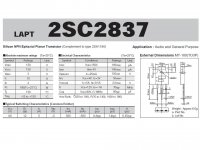
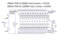
The Sanken 2SC2837 NPN has a typical Ft = 70Mhz, and the 2SA1186 PNP complement has a typical Ft = 60Mhz. I have used them in several multi-transistor output stages because of the low input capacitance and high Ft. A 24 transistor output stage driving 300 watts into 8 ohm load at 20Khz simulates to 0.01% THD. Driving 1200 watts into 1 ohm simulates to 0.04% THD @20Khz.
A Spice simulation of a "typical complementary topology" Class AB amp using global negative feedback driving 300 watts into 8 ohms at 20Khz simulates to 0.0002% THD. The idle power is less than 70 watts. Global feeback improves dampening.
With 70Mhz output transistors, it is difficult to find pre-driver transistors with both enough Ft (150-300Mhz rule of thumb) and enough power dissipation (20 watts) to take full advantage of the fast outputs. Krell often parallels several transistors for the pre-driver, perhaps to get optimum Ft, perhaps because they put their output transistors on several physically seperate heatsinks and use separate pre-drivers with each output group.
Anyone know of a 150Mhz, 160V, 20-30 watt pre-driver pair?
I expect a CLC power supply filter on expensive amps.
Attachments

Last edited:
- Status
- This old topic is closed. If you want to reopen this topic, contact a moderator using the "Report Post" button.
- Home
- Amplifiers
- Solid State
- Dan d'Agostino MOMENTUM: Sonic Character like pure ClassA/SE despite low Idle Power ?