My preferred are Toshiba 2sc 5171 / 2SA1930
http://ampslab.com/Freewares/2sc5171.pdf
This is an ISO-TO220 outline. Go to post #10 about
http://www.diyaudio.com/forums/solid-state/125321-replacement-2sa1930-2sc5171.html
Do you know the non isolated type number (ordinary TO220 version) ?
Thank you for this advice. Are there also types in non SMT (SMD) outline (i. e. with a hole for mounting on a heatsink) where is inside the same chip structure resp. the same manufacturing process ?Maybe this comes close :
http://semicon.sanyo.com/en/ds_e/EN2262D.pdf
Last edited:
A 24 transistor output stage driving 1200 watts
One would expect SOA to be a problem again with those devices for the 1200W/2 spec.
Yes, I think so, too. The use of 12 pairs means, that 100W for each pair must be necessary.One would expect SOA to be a problem again with those devices for the 1200W/2 spec.
The formula for the output peak power is - if I remember correctly - Vdd x Vdd x 8 x R-load. If I assume 100V (= Vdd) supply voltage and 8 ohms load I get 156,25 W peak power resp. ~110W eff power (measured by a sine wave signal).
By the use of normal TO220 or TO132 outlines much more devices much be operate in parallel to get the wanted reliability at 2 ohms load.
Therefore I assume, larger outlines like TO247, JAP03, MT-100 or TOP-3 must be in use. But perhaps in the meantime there are newer TO-220 outlines with lower thermal transition resistance available.
The Sanken 2SC2837 NPN has a typical Ft = 70Mhz, and the 2SA1186 PNP complement has a typical Ft = 60Mhz. I have used them in several multi-transistor output stages because of the low input capacitance and high Ft. A 24 transistor output stage driving 300 watts into 8 ohm load at 20Khz simulates to 0.01% THD. Driving 1200 watts into 1 ohm simulates to 0.04% THD @20Khz.
A Spice simulation of a "typical complementary topology" Class AB amp using global negative feedback driving 300 watts into 8 ohms at 20Khz simulates to 0.0002% THD. The idle power is less than 70 watts. Global feeback improves dampening.
With 70Mhz output transistors, it is difficult to find pre-driver transistors with both enough Ft (150-300Mhz rule of thumb) and enough power dissipation (20 watts) to take full advantage of the fast outputs. Krell often parallels several transistors for the pre-driver, perhaps to get optimum Ft, perhaps because they put their output transistors on several physically seperate heatsinks and use separate pre-drivers with each output group.
Anyone know of a 150Mhz, 160V, 20-30 watt pre-driver pair?
I expect a CLC power supply filter on expensive amps.
Perhaps instead of the good known push pull driver stage (i. e. the first stage of the push pull darlington buffer) there is a single ended pure class A MOSFET driver stage (follower topology) in use - like Andrea Ciuffoli's Power Follower about
http://www.audiodesignguide.com/PowerFollower/index.html
but suited/appropriate as driving stage for a very large amount of parallel operated BjT devices.
Such an idea I had already several years ago, but unfortunately not the time, to realize that idea and checking out the results.
OTOH - this topology I haven't see until now in commercial amp devices and thus this could be one of the details of d'Agostino's circuit topology. I am sure, if there was make a good evaluation work, this topology operates in the desired manner.
Last edited:
Fwiw, various Krell models of the last decade use power devices in the output stages that have the TO-3PF package.
The Sanken complementary pair that fits the 150V/14A description of Krell is the A1860/C4886.
(Sanken types in that package with really high Ft, plus sufficient SOA for 1200W/2, are darlingtons)
The Sanken complementary pair that fits the 150V/14A description of Krell is the A1860/C4886.
(Sanken types in that package with really high Ft, plus sufficient SOA for 1200W/2, are darlingtons)
Last edited:
For certainly speakers 1200W output power isn't enough even for home audio.Tief you anticipate that some idiot will run the amp at 1200 watt into 2 ohms continuously using a sine wave. This is not a weapon it is an entertainment system. I cannot imagine it will be entertaining.
Keep in mind the correlations between the increae of the output power and the perceived loudness, what you hear. Have a look to the power meters of various amps like Accuphase - a scale bar means power x 10 (following logarithmic subdivision is common: 1mW-10mW-0,1W-1W-10W-100W-1000W-10000W).
I cannot imagine, it will be entertaining when there are too low output power by low efficiency speakers (always clipping effect). In such cases the amp must be a weapon.
OTOH - the other way is to order a speaker like the "royal devices" bass horn so as mid-high frequency horns from ALE-Goto (goodsoundclub). Then you are right with your estimate in your last post.
Does anyone have experience with an effective output error correction circuit for 24 - 32 output transistors? I would appreciate some education and a circuit I can Spice.
When I use the Hawksford error correction circuit with 24 -32 output transistors I have not been able to get better than a factor of 4x reduction in 20Khz THD for 8-ohm loads. Global feedback reduces 20Khz THD by 100-1000x.
Krell has several patents on methods to control the output bias to reduce unnecessary power dissipation. Some have clever analog circuits which monitor output temperature, output current, and input signal levels to set the bias current. Some use a microprocessor to also include SOA of the output to assure safe operation with crazy loads plus optimize hfe. I suspect Dan used the best Krell bias control and reliability technology in his new amp.
An interesting approach is that one from the brand Linn (model "Klout").Does anyone have experience with an effective output error correction circuit for 24 - 32 output transistors? I would appreciate some education and a circuit I can Spice.
When I use the Hawksford error correction circuit with 24 -32 output transistors I have not been able to get better than a factor of 4x reduction in 20Khz THD for 8-ohm loads. Global feedback reduces 20Khz THD by 100-1000x.
Krell has several patents on methods to control the output bias to reduce unnecessary power dissipation. Some have clever analog circuits which monitor output temperature, output current, and input signal levels to set the bias current. Some use a microprocessor to also include SOA of the output to assure safe operation with crazy loads plus optimize hfe. I suspect Dan used the best Krell bias control and reliability technology in his new amp.
go therefore to the attached schematics by post #50 about
http://www.diyaudio.com/forums/solid-state/167580-output-capacitor-subjective-objective-views-5.html
Bassic idea is herte the use of a regulated power supply include implementing all kinds of wanted protections for the power amp.
An other approch is the use of emitter resistors in such large value, so for the current protector serves the resistor itself.
And an other possible again is the use of independend amplifiers, that works in parallel at whole in a great amount (often to observe by iC amps/Chip Amps - e. g. TDA7293, but also possible by discrete topologies).
The D'A amp would have to NOT use anything Krell, since that would bring up the spectre of lawsuits. Doubtless there is a lawsuit out there regarding his dismissal from Krell. At least this seems likely.
Line Source, has your sims shown a greater distortion reduction with Hawksford using only two output devices? And are you sim'ing just the output stage or an entire amp? Not being a sim expert, just asking logical questions, thinking something is awry in the sim. Too much benefit from global loop and not enough from Hawksford?
_-_-bear
Bassic idea is the use of a regulated power supply include implementing all kinds of wanted protections for the power amp.
Ah, as the Evo One.
http://www.krellonline.com/assets/amplifiers/evo1/fullsize/evo1-3_fs.jpg
Requires a third heatsink and a dozen power devices more though.
(to me, the Momentum sorta has the appearance of a Latino pimped Evo-1 case, lowrider with a tilted headlight after missing a curve
 )
)")
Duh, copper has a much Higher volume specific heat capacity than aluminum, well over 40pc higher.
As it should be : the higher VHC, the slower the change of temperature.
(specific heat of copper is lower, but that is not the equivalent of heat absorption capacity. unless the designer would be ignorant enough to use the weight of a heatsink as a parameter instead of volume & surface )
Plse Google your facts right and put them in the appropriate context. By volume Alu has a lower heat capacity than Cu, but not by weight, and more importantly, the ratio between heat capacity and thermal conductance is lower for Cu. And that was my point: if you want to have a massive array of matched output devices running as much as possible at the same temperature, copper is better.
vac
Line Source, has your sims shown a greater distortion reduction with Hawksford using only two output devices? And are you sim'ing just the output stage or an entire amp? _-_-bear
Hi Bear,
I am neither an expert nor a fan of Hawsford style error correction circuits. Personally, I prefer to increase the number of output transistors to get a high damping factor, and use TMC global feedback on a complementary symmetrical topology with optimal Class AB bias.
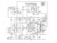
I have simulated the "End Millennium" designed by L.C. Audio Technology and have seen a 20x reduction in 20Khz THD when a high inductance, low impedance speaker model was used. Under real speaker load models the THD will reach 0.1% - 0.2% even with Hawksford. Considering the 0.27 Ohm emitter resistors in the output, the Hawksford circuit does a good job against Ohm's law. In the test literature, Dan's Momentum Amp THD is similar.
So, once again the buyer must trust their own ears, or trust the advice of a golden ear owner. Does low THD from global feedback sound better than modest THD with a clever use of local feedback as in Momentum or End Millennium?
Attachments
What about suitable driver transistors?
The common MJE1503x series are too slow.
The speed of the driver stage is determined as much by the impedance of the preceeding stage as it is by the device itself. It's also common for many designs to need additional CB capacitance - to ensure hf stability, so there are often practical limits to driver speed. I have managed to use the fast Toshiba drivers in EF2 (Thermaltrak), but for unconditional stability it was necesary to degenerate the vas > 10MHz with a specific grade of ferrite bead. (a very good all round solution) Layout and RF groundplanes are also very important. Simulations are of course no help, you need a good (200MHz CRO) to see what's going on.
Hi Bear,
I have simulated the "End Millennium" designed by L.C. Audio Technology and have seen a 20x reduction in 20Khz THD when a high inductance, low impedance speaker model was used. Under real speaker load models the THD will reach 0.1% - 0.2% even with Hawksford. Considering the 0.27 Ohm emitter resistors in the output, the Hawksford circuit does a good job against Ohm's law. In the test literature, Dan's Momentum Amp THD is similar.
The beauty of designing your own power amp is being able to optimise the output zobel network to your speaker system. I also use conjugate load matching to keep the impedance purely resistive to > 200kHz.
For a commercial designer it's obviously a different story, and compromises need to be made.
- Status
- This old topic is closed. If you want to reopen this topic, contact a moderator using the "Report Post" button.
- Home
- Amplifiers
- Solid State
- Dan d'Agostino MOMENTUM: Sonic Character like pure ClassA/SE despite low Idle Power ?